Product Guide
Linux PC
AI Accelerator Card
LLM-8850 Card
Large Language Models
AI & Agent
Real-Time AI Voice Assistant
XiaoZhi Voice Assistant
AtomS3R-M12 Volcengine Kit
Offline Voice Recognition
Industrial Control
IoT Measuring Instruments
Air Quality
PowerHub
Module13.2 PPS
VAMeter
T-Lite
Input & Output Devices
Ethernet Camera
PoECAM
Wi-Fi Camera
Unit CamS3/-5MP
AI Camera
LoRa & LoRaWAN
Motor Control
Restore Factory Firmware
DIP Switch Usage Guide
DIP Switch Pin Switching Instructions
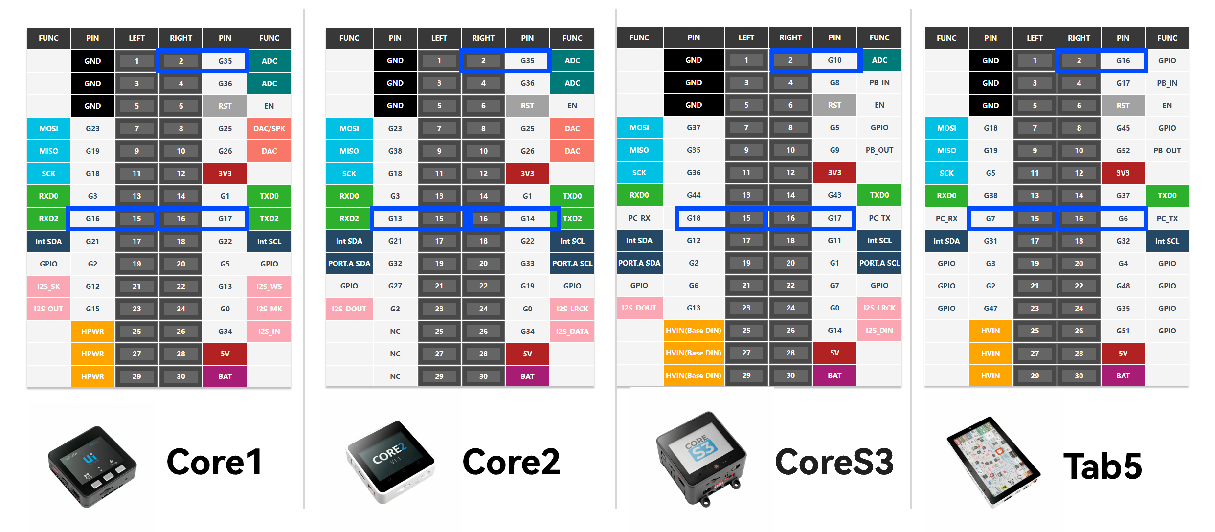
What is M5-Bus
M5-Bus is a stack expansion bus design adopted by M5Stack stacking series products (Module, Base). The interface uses 2x15P@2.54mm pin headers/sockets. The Core series controllers can quickly stack different modules via the M5-Bus to achieve functional expansion. Its fixed positions define power pins such as GND, 5V, 3V3, and BAT, ensuring compatibility with various devices; other pins vary depending on the controller model, so you need to configure your program according to the actual pin mapping.
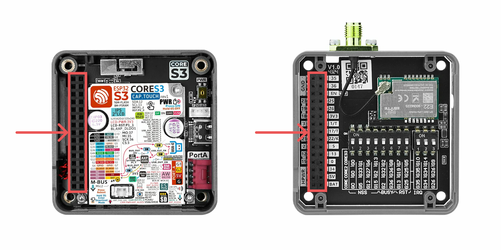
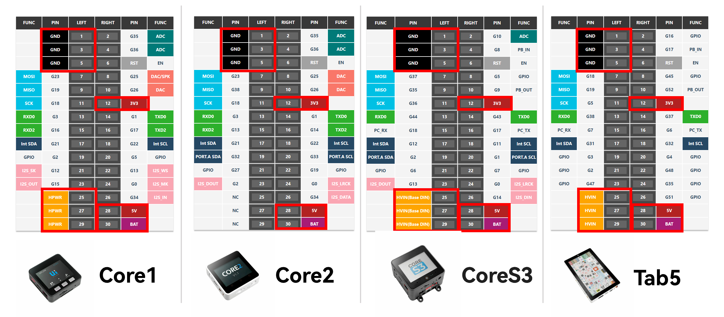
Fixed Function Pins
The pin numbers of M5-Bus are fixed starting from the GND pin at the top left corner, numbered from 1 to 30. This sequence is consistent across all controllers. The pins marked with a red box are fixed-function pins (power and GND, etc.), while other pins may have different functions or GPIO mappings depending on the main controller.
What is a DIP Switch
A DIP Switch is a toggle switch. It is used to flexibly change the connection of key module pins to adapt to different controller models. For example, in the case of Module GPS v2.0, there are three switchable pins: TXD, RXD, and PPS. Two onboard DIP switches control which pins these signals are connected to.
DIP Switch1’s switches 1–4 control TXD, switches 5–8 control RXD; DIP Switch2 is used to control PPS.
To avoid pin conflicts, typically each function pin only needs to be switched to one pin based on actual usage requirements. For example, in the following configuration, the 1st and 5th switches on DIP Switch1 are set to ON, the 2nd switch on DIP Switch2 is set to ON, and all other switches are set to OFF.
Based on the PCB silkscreen reference:
- For Basic, the G17 pin; for Core2, the G14 pin; for CoreS3, the G17 pin will be connected to TXD.
- For Basic, the G16 pin; for Core2, the G13 pin; for CoreS3, the G18 pin will be connected to RXD.
- For Basic / Core2, the G35 pin; for CoreS3, the G10 pin will be connected to PPS.
When programming the device, you must modify the corresponding pin configuration according to the actual pin connections.
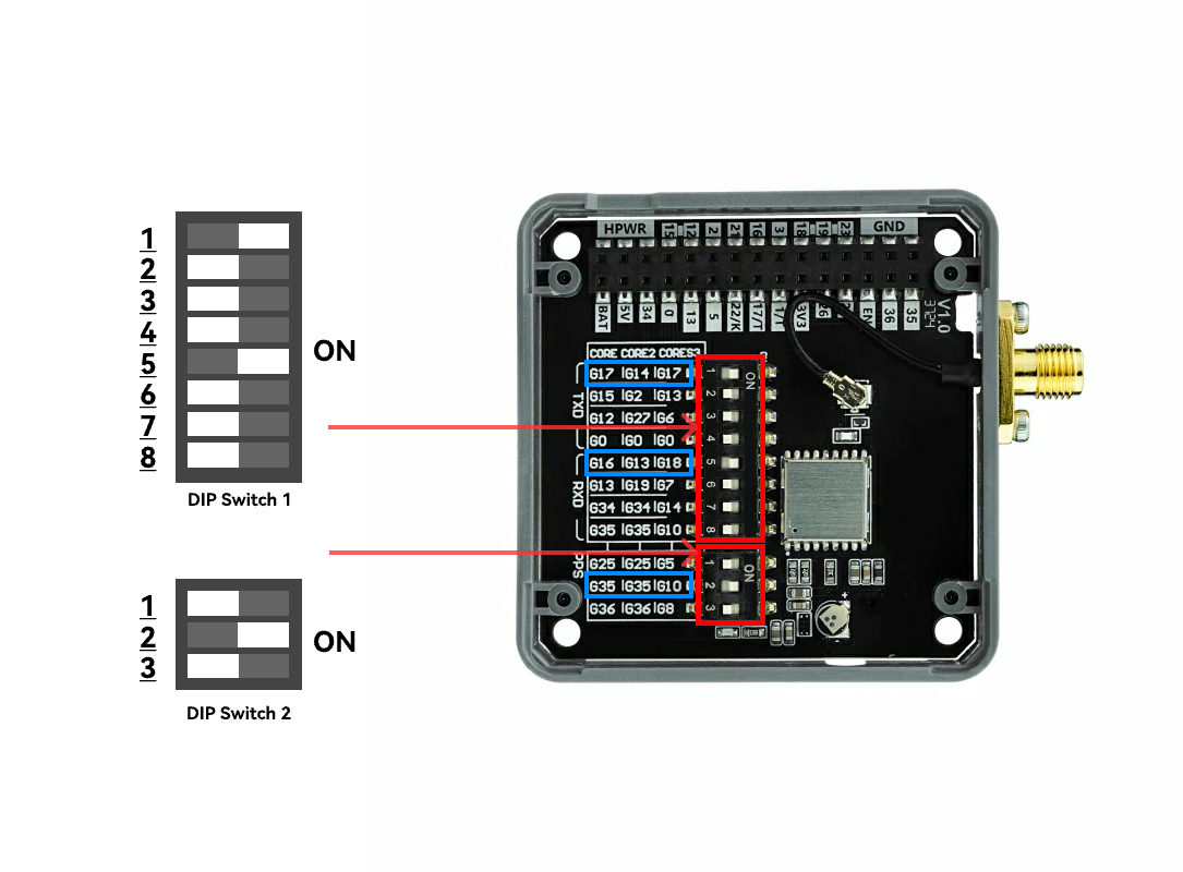
The DIP switch’s corresponding positions and numbering connected to the M5-Bus are fixed (indicated by blue box).
If the PCB silkscreen’s I/O reference table does not include the controller model you are currently using, you can refer to the existing device’s silkscreen PinMap to identify which M5-Bus pins the DIP switch connects to, and then map those to the corresponding pins of your current controller.