Arduino Quick Start
2. Devices & Examples
3. M5Unified
4. M5GFX
5. Extensions
Unit
Atomic
Base
Tab5
IoT
Accessories
Unit UWB Arduino Tutorial
1. Preparations
Environment Setup: Refer to Arduino IDE Getting Started Guide to complete IDE installation, and install corresponding board manager and required driver libraries based on the development board used.
Required Driver Libraries:
Required Hardware Products:

2. Notes
3. Example Program
This tutorial uses one CoreS3 and two AtomS3 as main controllers, paired with three Unit UWB modules. The Unit UWB module communicates via UART. Modify pin definitions in the program according to actual circuit connections. The corresponding UART IOs after connecting to CoreS3 and AtomS3 are both
G1 (RX)andG2 (TX).The Unit UWB example program provides an enumeration
UWB_Anchor_numfor Anchor numbering settings. Users can modify the value in functionsetupmode()as needed (any number works in Tag mode).Tag program section:
/*
 * SPDX-FileCopyrightText: 2025 M5Stack Technology CO LTD
 *
 * SPDX-License-Identifier: MIT
 *
 *
 * @Hardwares: M5CoreS3 + Unit UWB
 * @Dependent Library:
 * M5Unified: https://github.com/m5stack/M5Unified
 * M5Unit_UWB: https://github.com/m5stack/M5Unit-UWB
 */
#include <M5Unified.h>
#include "M5_UWB.h"

M5_UWB Unit_UWB;
UWB_Mode        Unit_UWB_Mode   = UWB_Mode_Tag;
UWB_Anchor_num  Unit_UWB_Tag    = UWB_Anchor_0; // Select the anchor

bool Uwb_Init = 0;
uint8_t Tag_num       = 0;
uint8_t UI_Init_flag = 0;
void UWB_UI_display();

void setup(){
    M5.begin();
    Serial.begin(115200);
    Unit_UWB.begin(&Serial2, 22, 21, 115200);
    Uwb_Init = Unit_UWB.setupmode(Unit_UWB_Mode, Unit_UWB_Tag, (char *)"5"); // Set the UWB mode and distance value
    if(Uwb_Init){
        Serial.println("UWB Init Success");
    } else {
        Serial.println("UWB Init Failed");
    }
    M5.Display.fillScreen(WHITE);
    M5.Display.setTextColor(BLACK);
    M5.Display.setFont(&fonts::FreeMonoBold9pt7b);
    delay(100);
}

void loop(){
    Tag_num = Unit_UWB.readstring();
    UWB_UI_display();
    delay(100);
}

void UWB_UI_display(){
    if(UI_Init_flag == 0){
      M5.Display.fillScreen(WHITE);
      M5.Display.setCursor(0, 0);
      M5.Display.println("UWB Test");
      M5.Display.println("Tag Model, Distance: \r\n(uint: m)\r\n");
      UI_Init_flag = 1;
    }
    M5.Display.fillRect(0, 60, 340, 240, WHITE);
    M5.Display.setCursor(0, 60);
    M5.Display.print(Unit_UWB.DATA);
    Serial.println(Unit_UWB.DATA);
}- Anchor program section:
/*
* SPDX-FileCopyrightText: 2025 M5Stack Technology CO LTD
*
* SPDX-License-Identifier: MIT
*
*
* @Hardwares: AtomS3 + Unit UWB
* @Platform Version: Arduino M5Stack Board Manager v2.1.3
* @Dependent Library:
* M5Unified: https://github.com/m5stack/M5Unified
* M5Unit_UWB: https://github.com/m5stack/M5Unit-UWB
*/
#include <M5Unified.h>
#include "M5_UWB.h"
M5_UWB Unit_UWB;
UWB_Mode Unit_UWB_Mode = UWB_Mode_Base;
UWB_Anchor_num Unit_UWB_Anchor = UWB_Anchor_1; // Select the anchor point
bool Uwb_Init = 0;
uint8_t Tag_num = 0;
uint8_t UI_Init_flag = 0;
void UWB_UI_display();
const char* getAnchornNum(UWB_Anchor_num Num) {
switch (Num) {
case UWB_Anchor_0: return "Base_0";
case UWB_Anchor_1: return "Base_1";
case UWB_Anchor_2: return "Base_2";
case UWB_Anchor_3: return "Base_3";
case UWB_Anchor_4: return "Base_4";
default: return "Unknown";
}
}
void setup(){
M5.begin();
Serial.begin(115200);
Unit_UWB.begin(&Serial2, 1, 2, 115200);
Uwb_Init = Unit_UWB.setupmode(Unit_UWB_Mode, Unit_UWB_Anchor, (char *)"5"); // Set the UWB mode and distance value
if(Uwb_Init){
Serial.println("UWB Init Success");
} else {
Serial.println("UWB Init Failed");
}
M5.Display.fillScreen(WHITE);
M5.Display.setTextColor(BLACK);
M5.Display.setFont(&fonts::FreeMonoBold9pt7b);
delay(100);
}
void loop(){
Tag_num = Unit_UWB.readstring();
UWB_UI_display();
delay(100);
}
void UWB_UI_display(){
if(UI_Init_flag == 0){
M5.Display.fillScreen(WHITE);
M5.Display.setCursor(0, 0);
M5.Display.println("UWB Test");
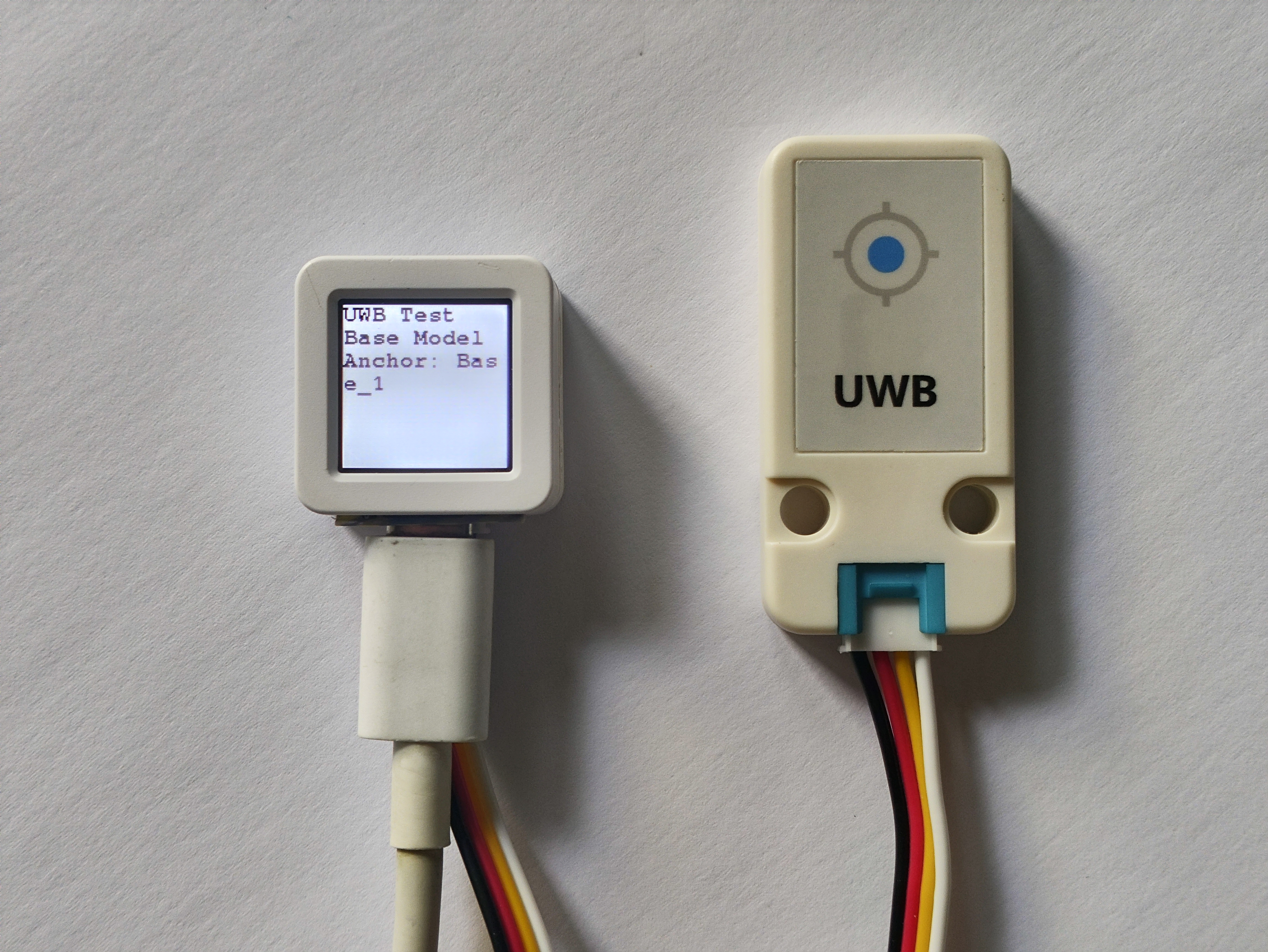
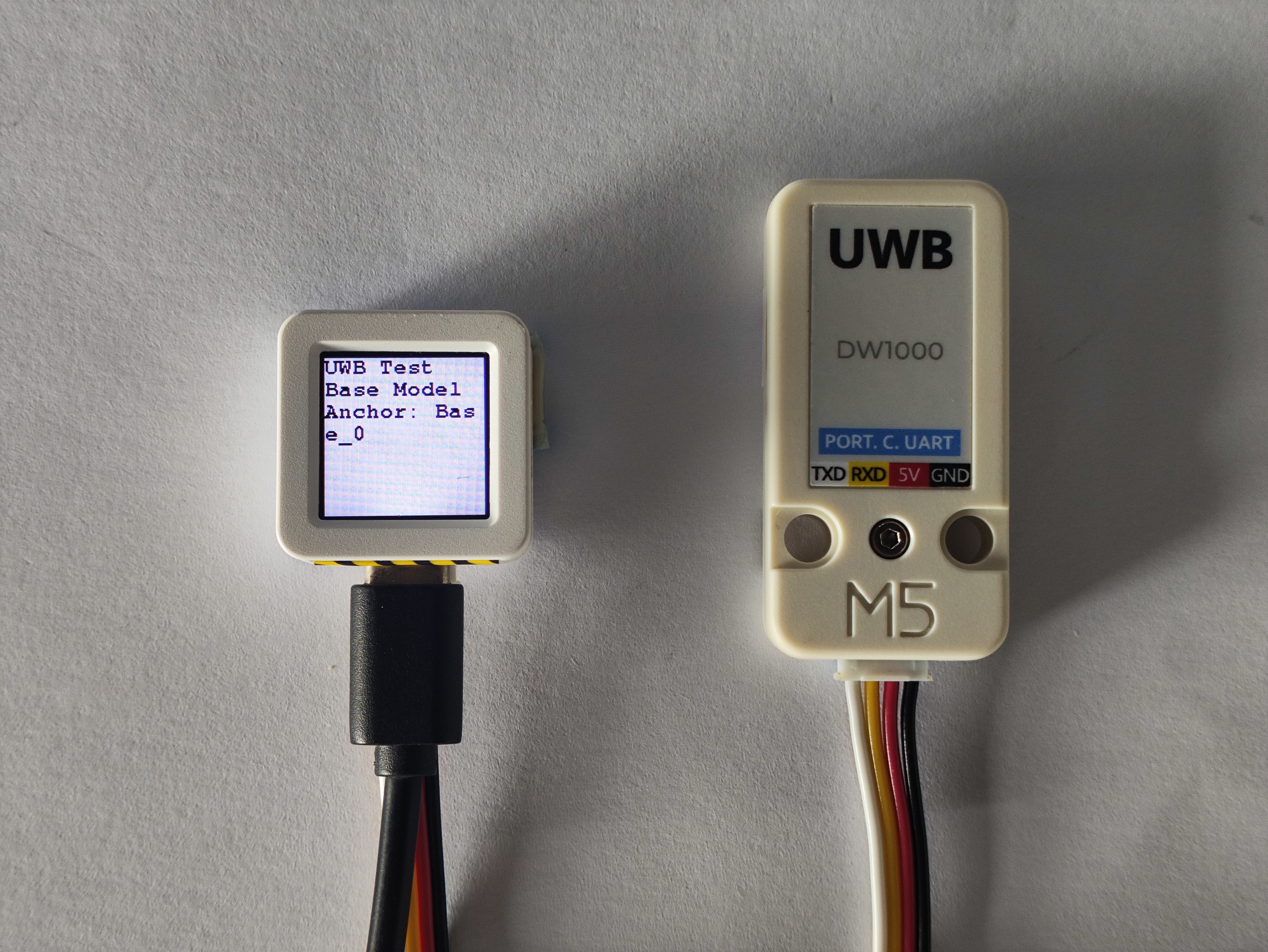
M5.Display.println("Base Model");
const char * current_num = getAnchornNum(Unit_UWB_Anchor);
M5.Display.printf("Anchor: %s", current_num);
UI_Init_flag = 1;
}
M5.Display.setCursor(0, 80);
M5.Display.print(Unit_UWB.DATA);
Serial.println(Unit_UWB.DATA);
}3. Compile and Upload
Download Mode: Different devices need to enter download mode before programming. This step may vary depending on the main controller. For details, refer to the Arduino IDE Getting Started Guide and check the device-specific programming tutorial at the bottom of the page.
CoreS3 and AtomS3 share the same programming method: Press and hold the reset button (about 2 seconds) until the internal green LED lights up, then release. The device is now in download mode and ready for programming.
.gif)
- Select the device port and click the upload button in the top-left corner of Arduino IDE. Wait for the program to compile and upload to the device.

4. Indoor Ranging
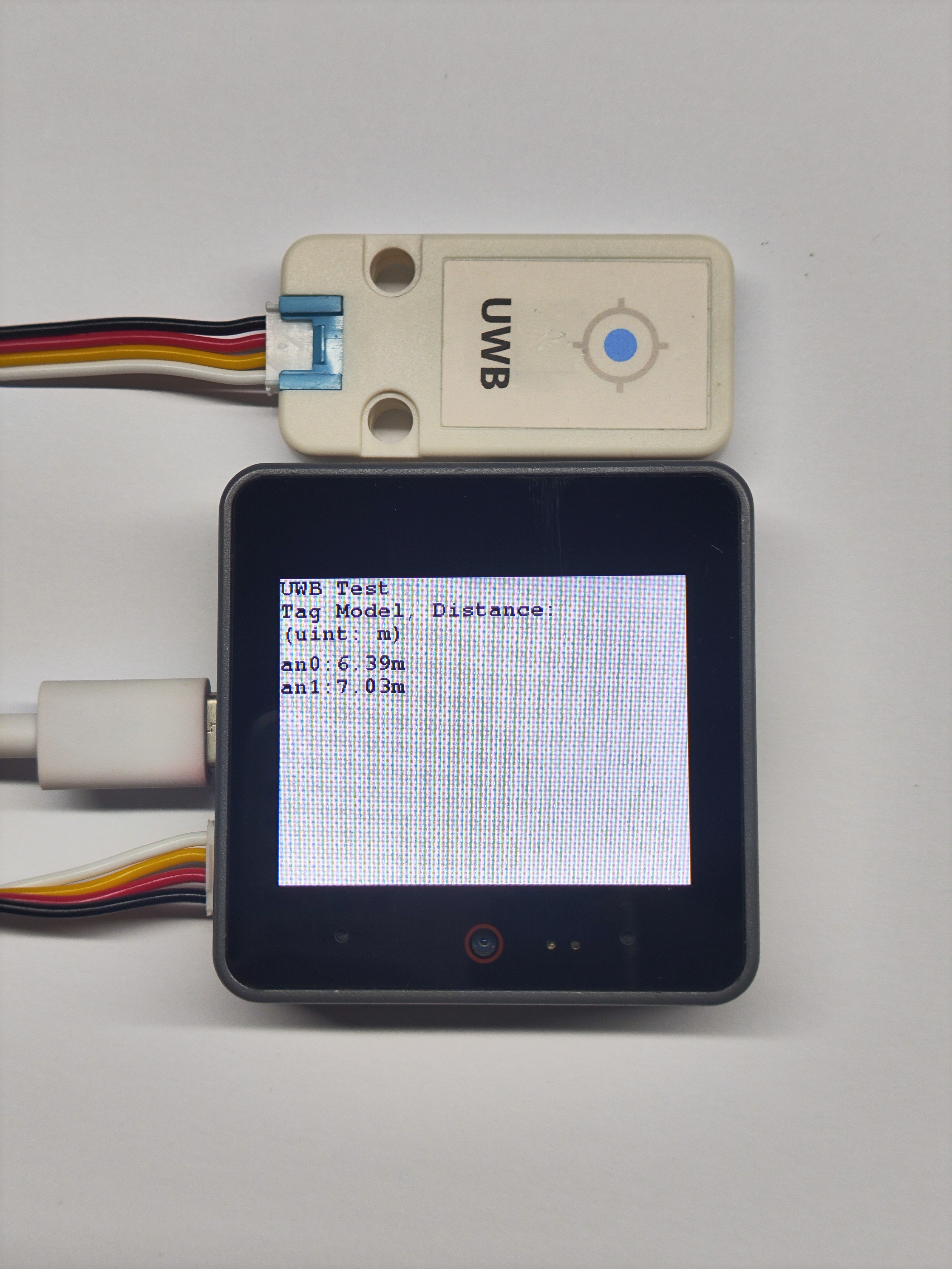
Here we use two AtomS3 connected to Unit UWB modules as Anchors, and one CoreS3 connected to Unit UWB module as Tag (note: the distance between Anchor and Tag should preferably be between 5-50m).
Tag operation effect:
- Anchor operation effect: