Arduino入門
2. デバイス&サンプル
3. M5Unified
4. M5GFX
5. 拡張モジュール&サンプル
Unit
Atomic
Tab5
IoT
アクセサリー
Module COMMU Arduino チュートリアル
1. 準備作業
- 環境設定:Arduino IDE 入門チュートリアルを参考に IDE のインストールを完了し、実際に使用する開発ボードに応じてボードマネージャーと必要なドライバライブラリをインストールしてください。
- 必要なドライバライブラリ:
- 必要なハードウェア製品:
- CoreS3
- Basic v2.7
- COMMU Module
- Unit ENV-III (この製品は I2C インターフェースのテスト時のみ使用)
2. 注意事項
3. CANバス送受信実験
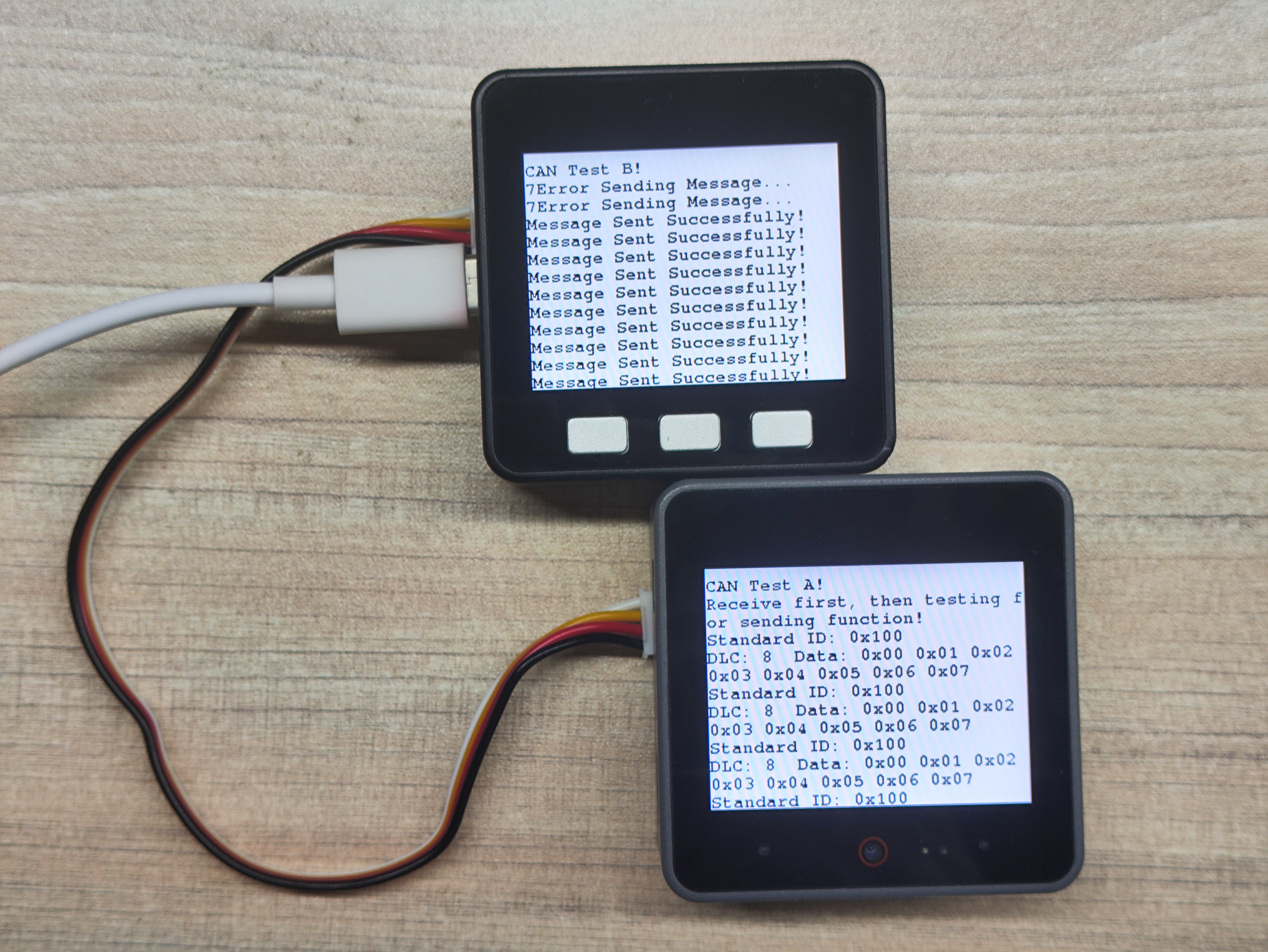
この実験では Basic v2.7 を CAN 受信機として、CoreS3 を CAN 送信機として使用します。実際の接続に応じてINTピンとCSピンの番号を修正してください。
CAN バス通信は双方向の同期が成功して初めて送受信が可能になることに注意してください。Basic v2.7 ホストに表示される 7Error Sending Message..というメッセージは、送信側が先に起動し、受信側が後から起動したため、送信側が最初に受信側からの応答を正しく取得できなかったことを示しています。
- CAN 受信機プログラム:
/**
 * @file Commu_can_receiver
 * @author Zovey (liangzhuowei@m5stack.com)
 * @brief
 * @version 0.1
 * @date 2025-06-27
 *
 *
 * @Hardwares: M5CoreS3 + Module COMMU
 * @Dependent Library:
 * M5UnitENV: https://github.com/m5stack/M5Unit-ENV
 * MCP_CAN_lib: https://github.com/coryjfowler/MCP_CAN_lib
 */

#include <M5Unified.h>
#include <mcp_can.h>

byte data[8] = {0x00, 0x01, 0x02, 0x03, 0x04, 0x05, 0x06, 0x07};

long unsigned int rxId;
unsigned char len = 0;
unsigned char rxBuf[8];
char msgString[128];

#define CAN0_INT 13
MCP_CAN CAN0(6);

void init_can();
void test_can();

void setup() {
    M5.begin();
    M5.Power.begin();
    Serial.begin(115200);
    Serial2.begin(9600, SERIAL_8N1, 16, 17);

    M5.Display.fillScreen(WHITE);
    M5.Display.setTextColor(BLACK);
    M5.Display.setFont(&fonts::FreeMonoBold9pt7b);
    delay(500);

    init_can();
    Serial.println("Test CAN...");
}

void loop() {
    test_can();
}

void init_can() {
    M5.Display.setTextSize(1);
    M5.Display.setCursor(0, 10);
    M5.Display.fillScreen(WHITE);
    delay(500);

    M5.Display.printf("CAN Test A!\n");
    M5.Display.printf("Receive first, then testing for sending function!\n");

    if (CAN0.begin(MCP_ANY, CAN_1000KBPS, MCP_8MHZ) == CAN_OK)
        Serial.println("MCP2515 Initialized Successfully!");
    else
        Serial.println("Error Initializing MCP2515...");

    CAN0.setMode(MCP_NORMAL);
    pinMode(CAN0_INT, INPUT);

    Serial.println("MCP2515 Library Receive Example...");
}

void test_can() {
    if (!digitalRead(CAN0_INT)) {
        CAN0.readMsgBuf(&rxId, &len, rxBuf);

        if ((rxId & 0x80000000) == 0x80000000)
            sprintf(msgString, "Extended ID: 0x%.8lX  DLC: %1d  Data:", (rxId & 0x1FFFFFFF), len);
        else
            sprintf(msgString, "Standard ID: 0x%.3lX  \nDLC: %1d  Data:", rxId, len);

        Serial.print(msgString);
        M5.Display.printf(msgString);

        if ((rxId & 0x40000000) == 0x40000000) {
            sprintf(msgString, " REMOTE REQUEST FRAME");
            Serial.print(msgString);
            M5.Display.printf(msgString);
        } else {
            for (byte i = 0; i < len; i++) {
                sprintf(msgString, " 0x%.2X", rxBuf[i]);
                Serial.print(msgString);
                M5.Display.printf(msgString);
            }
        }
        M5.Display.printf("\n");
        Serial.println();
    }
}- CAN 送信機プログラム:
/**
 * @file Commu_can_transimmiter
 * @author Zovey (liangzhuowei@m5stack.com)
 * @brief
 * @version 0.1
 * @date 2025-06-27
 *
 *
 * @Hardwares: M5CoreS3 + Module COMMU
 * @Dependent Library:
 * MCP_CAN_lib: https://github.com/coryjfowler/MCP_CAN_lib
 */

#include <M5Unified.h>
#include <mcp_can.h>

byte data[8] = {0x00, 0x01, 0x02, 0x03, 0x04, 0x05, 0x06, 0x07};

long unsigned int rxId;
unsigned char len = 0;
unsigned char rxBuf[8];
char msgString[128];

#define CAN0_INT 15
MCP_CAN CAN0(12);

void init_can();
void test_can();

void setup() {
    M5.begin();
    M5.Power.begin();
    Serial.begin(115200);
    Serial2.begin(9600, SERIAL_8N1, 16, 17);        // Pins of RS485

    M5.Display.fillScreen(WHITE);
    delay(500);
    M5.Display.setTextColor(BLACK);
    M5.Display.setFont(&fonts::FreeMonoBold9pt7b);

    init_can();
    Serial.println("Test CAN...");
}

void loop() {
    delay(500);
    if (M5.BtnA.wasPressed()) {
        M5.Display.clear();
        M5.Display.printf("CAN Test B!\n");
        M5.Display.fillScreen(WHITE);
        init_can();
    }
    test_can();
    M5.update();
}

void init_can() {
    M5.Display.setTextSize(1);
    M5.Display.setCursor(0, 10);
    M5.Display.fillScreen(WHITE);
    M5.Display.printf("CAN Test B!\n");

    if (CAN0.begin(MCP_ANY, CAN_1000KBPS, MCP_8MHZ) == CAN_OK)
        Serial.println("MCP2515 Initialized Successfully!");
    else
        Serial.println("Error Initializing MCP2515...");

    CAN0.setMode(MCP_NORMAL);
}

void test_can() {
    byte sndStat = CAN0.sendMsgBuf(0x100, 0, 8, data);
    if (sndStat == CAN_OK) {
        Serial.println("Message Sent Successfully!");
        M5.Display.printf("Message Sent Successfully!\n");
    } else {
        Serial.printf("%d", sndStat);
        Serial.println("Error Sending Message...");
        M5.Display.printf("%d", sndStat);
        M5.Display.printf("Error Sending Message...\n");
    }
    delay(200);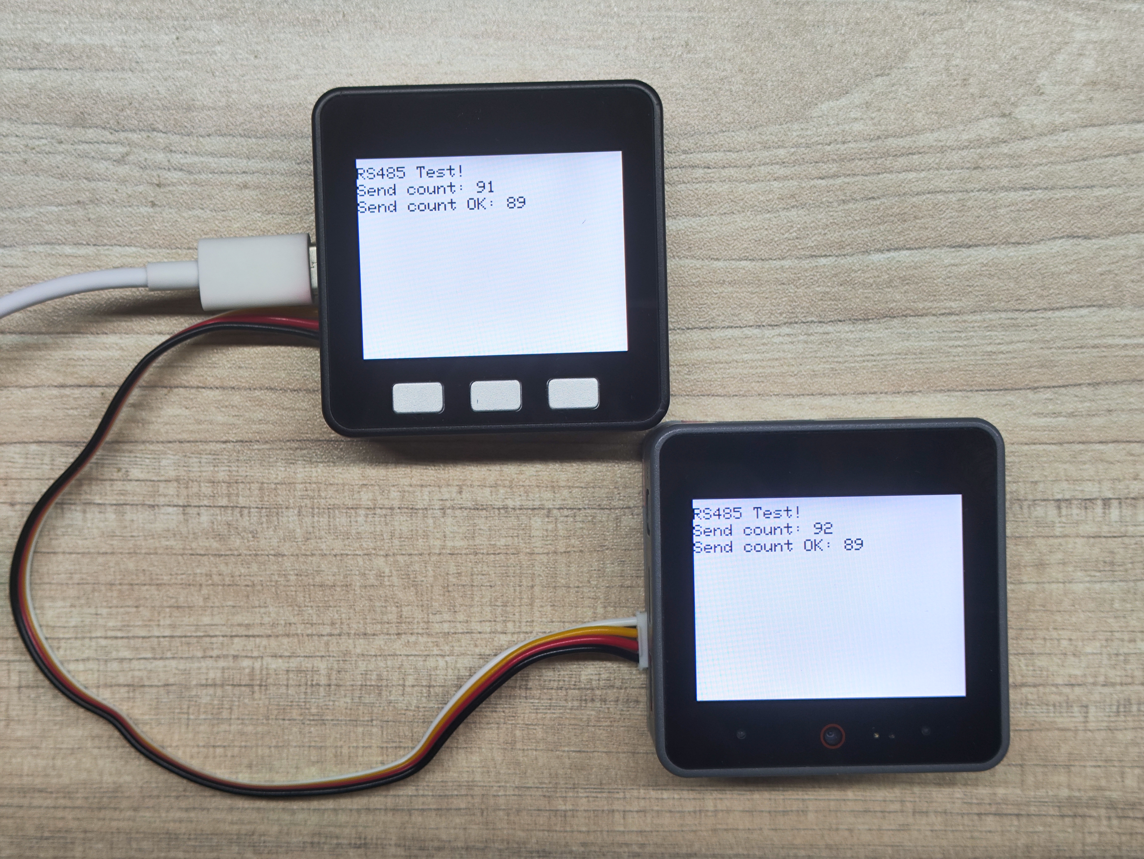
}4. RS485 送受信実験
本実験では2台のデバイス間での RS485 通信を実証します。異なるホストデバイスに書き込む際は、実際の接続要件に応じてサンプルプログラム内のピン定義を修正してください。
- RS485 送受信プログラム:
/**
 * @file RS485_Test
 * @author Zovey (liangzhuowei@m5stack.com)
 * @brief
 * @version 0.1
 * @date 2025-06-27
 *
 *
 * @Hardwares: M5CoreBasic + M5CoreS3 + Module COMMU
 */

#include <M5Unified.h>

// RS485 data buffer
// FH  len  fun   data   CRC
// 01 aa 00 09 00 01 00 01 b6
char uart_buffer[9] = {0x01, 0xaa, 0x00, 0x09, 0x00, 0x01, 0x00, 0x01, 0xb6};
char comchar;
char Num       = 0;
int Send_Count = 0;
int Send_OK    = 0;
int RECcheck   = 0;
char stringnum = 0;

typedef union {
    struct { char buff[10]; };
    struct { short frame; short datalength; short function; short data; char check; };
    struct {
        char framelow;
        char framehigh;
        char datalengthlow;
        char datalengthhigh;
        char functionhigh;
        char functionlow;
        char datahigh;
        char datalow;
    };
} uart_data;

uart_data UART_DATA    = {0};
uart_data UART_RECDATA = {0};

void init_rs485();
void test_rs485();
void updatedata();

void setup() {
    M5.begin();
    M5.Power.begin();
    Serial.begin(115200);
    Serial2.begin(9600, SERIAL_8N1, 18, 17);

    M5.Display.fillScreen(WHITE);
    delay(500);
    M5.Display.setTextColor(BLACK);

    init_rs485();
    Serial.println("Test RS485...");
}

void loop() {
    if (M5.BtnA.wasPressed()) {
        M5.Display.clear();
        M5.Display.printf("RS485 Test!\n");
        M5.Display.fillScreen(WHITE);
        init_rs485();
        Serial.println("Test RS485...");
    }
    test_rs485();
    M5.update();
    delay(1000);
}

void init_rs485() {
    M5.Display.fillScreen(WHITE);
    delay(500);

    M5.Display.setTextSize(2);
    M5.Display.setCursor(0, 10);
    M5.Display.printf("RS485 Test!\n");
    Serial.println("RS485 Test A!\n");
    memcpy(UART_DATA.buff, uart_buffer, 9);

    updatedata();
}

void updatedata() {
    Send_Count = (Send_Count + 1) & 0xffff;
    UART_DATA.datahigh = (Send_Count & 0xff00) >> 8;
    UART_DATA.datalow  = Send_Count & 0xff;
    UART_DATA.check = UART_DATA.framelow + UART_DATA.framehigh + UART_DATA.datalengthlow + UART_DATA.datalengthhigh +
                      UART_DATA.functionlow + UART_DATA.functionhigh + UART_DATA.datalow + UART_DATA.datahigh;

    for (stringnum = 0; stringnum < 9; stringnum++) {
        Serial2.print(UART_DATA.buff[stringnum]);
        Serial.print(UART_DATA.buff[stringnum]);
        Serial.print(" ");
    }

    M5.Display.fillRect(0, 30, 300, 20, WHITE);
    M5.Display.setCursor(0, 30);
    M5.Display.printf("Send count: %d", Send_Count);

    M5.Display.fillRect(0, 50, 300, 20, WHITE);
    M5.Display.setCursor(0, 50);
    M5.Display.printf("Send count OK: %d\r\n", Send_OK);
}

void test_rs485() {
    while (Serial2.available() > 0) {
        Num = Serial2.readBytes(uart_buffer, 9);
        if (Num == 9) {
            memcpy(UART_RECDATA.buff, uart_buffer, 9);
            RECcheck = UART_RECDATA.framelow + UART_RECDATA.framehigh + UART_RECDATA.datalengthlow +
                       UART_RECDATA.datalengthhigh + UART_RECDATA.functionlow + UART_RECDATA.functionhigh +
                       UART_RECDATA.datalow + UART_RECDATA.datahigh;
            if (UART_RECDATA.check == (RECcheck & 0xff)) {
                Send_OK++;
            }
        }
        updatedata();
    }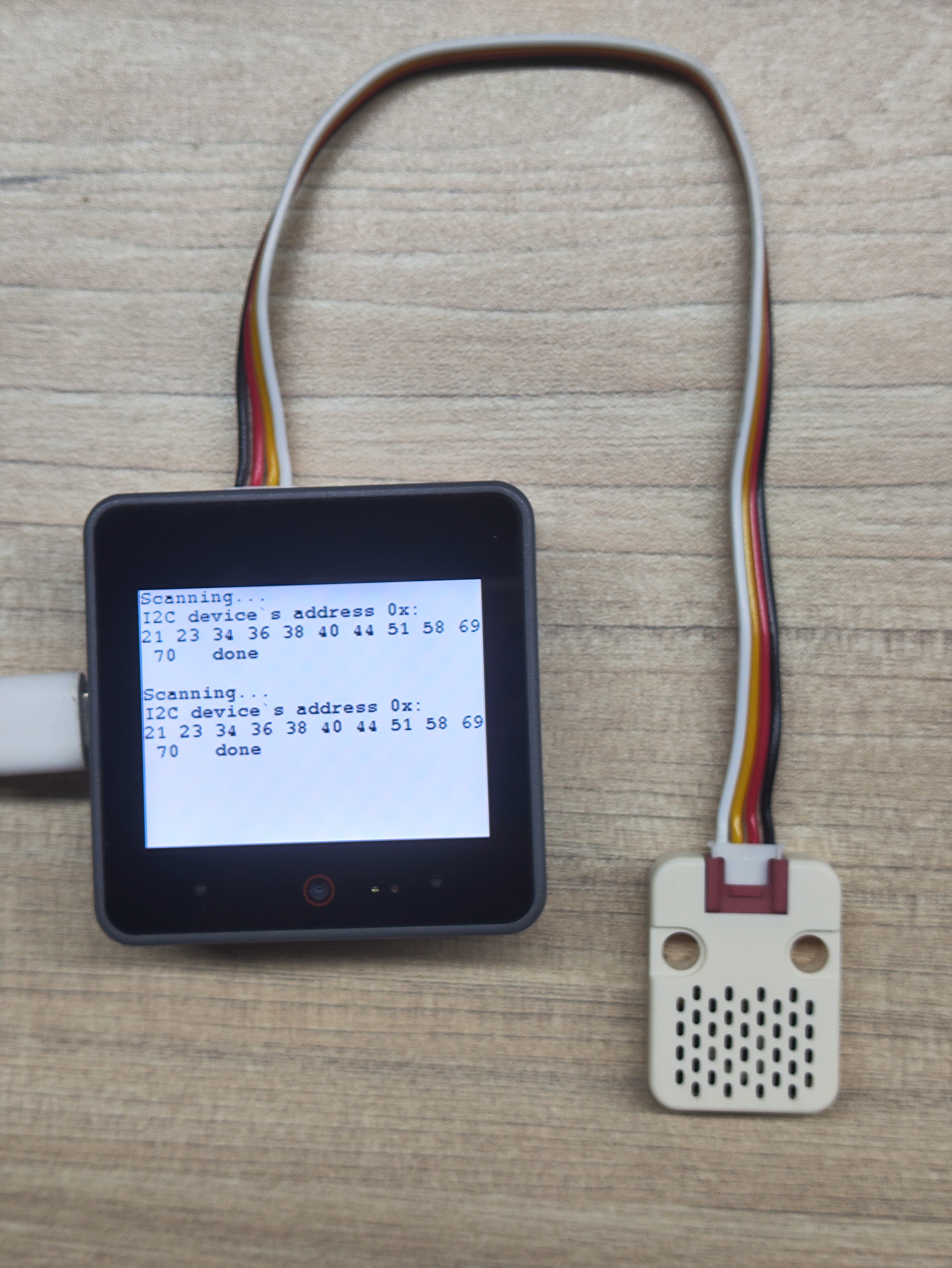
}5. I2C インターフェース実験
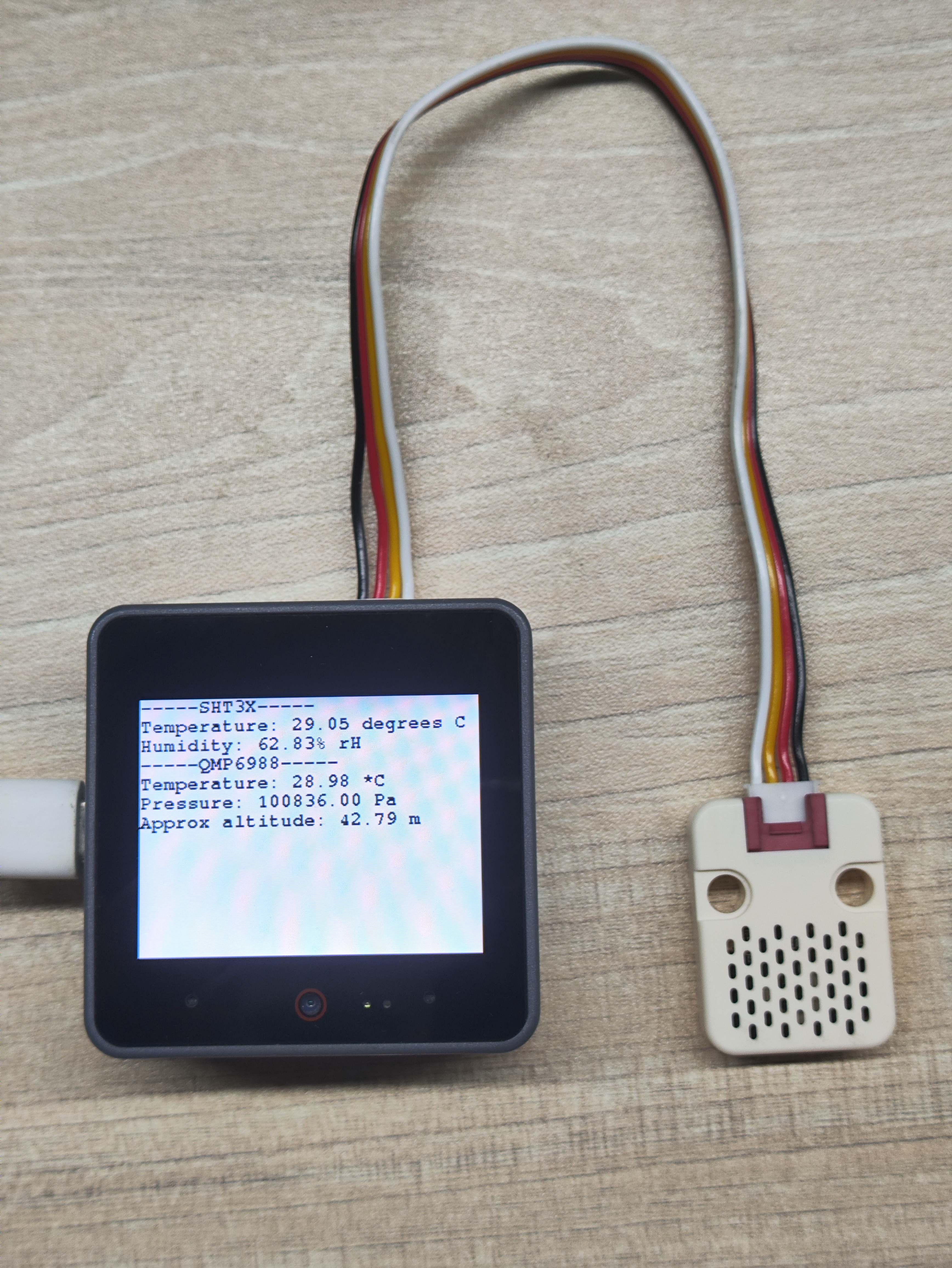
本実験では I2C インターフェースを介した周辺機器の駆動を実証します。異なるホストデバイスに書き込む際は、実際の接続要件に応じてサンプルプログラム内のピン定義を修正してください。本チュートリアルにおける I2C 周辺機器駆動実験では Unit ENV-III を例として使用していますが、I2C 通信実験では任意の I2C 周辺機器を使用してアドレスを取得できます。
- I2C アドレススキャン実験:
/**
 * @file IIC_Test
 * @author Zovey (liangzhuowei@m5stack.com)
 * @brief
 * @version 0.1
 * @date 2025-06-27
 *
 * @Hardwares: M5CoreS3 + Module COMMU
 */

#include "M5Unified.h"
#include <Wire.h>

uint8_t count = 0;

void setup() {
    M5.begin();
    Serial.begin(115200);
    Serial.println("I2C Address Scanning ...");
    Wire.begin(12, 11);
    M5.Display.fillScreen(WHITE);
    M5.Display.setTextColor(BLACK);
    M5.Display.setFont(&fonts::FreeMonoBold9pt7b);
    delay(500);
}

void loop() {
    byte error, address;
    int nDevices = 0;

    Serial.println("Scanning...");
    M5.Display.println("Scanning...");
    M5.Display.print("I2C device`s address 0x:\r\n");
    Serial.print("I2C device found at address 0x\r\n");
    for (address = 1; address < 127; address++) {
    Wire.beginTransmission(address); // Start transmitting to the specified address
    error = Wire.endTransmission(); // Check if there is any device response

    if (error == 0) {
        if (address < 16) Serial.print("0");
        Serial.println(address, HEX); // Output device address (hexadecimal)
        M5.Display.printf("%02X ",address);
        nDevices++;
    } else if (error == 4) {
        Serial.print("Unknown error at address 0x");
        if (address < 16) Serial.print("0");
        Serial.println(address, HEX);
        }
    }

    if (nDevices == 0) {
    Serial.println("No I2C devices found\n");
    M5.Display.println("No I2C devices found\n");
    } else {
    Serial.println("done\n");
    M5.Display.println("  done\n");
    }
    delay(5000); // Re-scan every five seconds
}- I2C 周辺機器駆動実験:
/**
 * @file IIC_Test
 * @author Zovey (liangzhuowei@m5stack.com)
 * @brief
 * @version 0.1
 * @date 2025-06-27
 *
 * @Hardwares: M5CoreS3 + Unit ENV_III + Module COMMU
 * @Dependent Library:
 * M5UnitENV: https://github.com/m5stack/M5Unit-ENV
 */

#include "M5Unified.h"
#include "M5UnitENV.h"

SHT3X sht3x;
QMP6988 qmp;

void setup() {
    M5.begin();
    Serial.begin(115200);

    M5.Display.fillScreen(WHITE);
    M5.Display.setTextColor(BLACK);
    M5.Display.setFont(&fonts::FreeMonoBold9pt7b);
    delay(500);

    if (!qmp.begin(&Wire, QMP6988_SLAVE_ADDRESS_L, 12, 11, 400000U)) {
        Serial.println("Couldn't find QMP6988");
        while (1) delay(1);
    }

    if (!sht3x.begin(&Wire, SHT3X_I2C_ADDR, 12, 11, 400000U)) {
        Serial.println("Couldn't find SHT3X");
        while (1) delay(1);
    }
}

void printSHT3X(const SHT3X& sht) {
    Serial.println("-----SHT3X-----");
    Serial.printf("Temperature: %.2f degrees C\nHumidity: %.2f%% rH\n",
                  sht.cTemp, sht.humidity);    M5.Display.fillScreen(WHITE);
    M5.Display.setCursor(0, 0);
    M5.Display.printf("-----SHT3X-----\r\n");
    M5.Display.printf("Temperature: %.2f degrees C\nHumidity: %.2f%% rH\n",
                      sht.cTemp, sht.humidity);
}

void printQMP6988(const QMP6988& qmp) {
    Serial.println("-----QMP6988-----");
    Serial.printf("Temperature: %.2f *C\nPressure: %.2f Pa\nApprox altitude: %.2f m\n",
                  qmp.cTemp, qmp.pressure, qmp.altitude);
    M5.Display.printf("-----QMP6988-----\r\n");
    M5.Display.printf("Temperature: %.2f *C\nPressure: %.2f Pa\nApprox altitude: %.2f m\n",
                     qmp.cTemp, qmp.pressure, qmp.altitude);
}

void loop() {
    if (sht3x.update()) printSHT3X(sht3x);
    if (qmp.update())   printQMP6988(qmp);
    delay(1000);
}6. コンパイルとアップロード
ダウンロードモード:デバイスによって、プログラム書き込み前にダウンロードモードに入る必要があります。この手順はメインコントロールデバイスによって異なる場合があります。詳細は、Arduino IDE入門チュートリアルページ下部のデバイスプログラミングチュートリアルリストを参照してください。
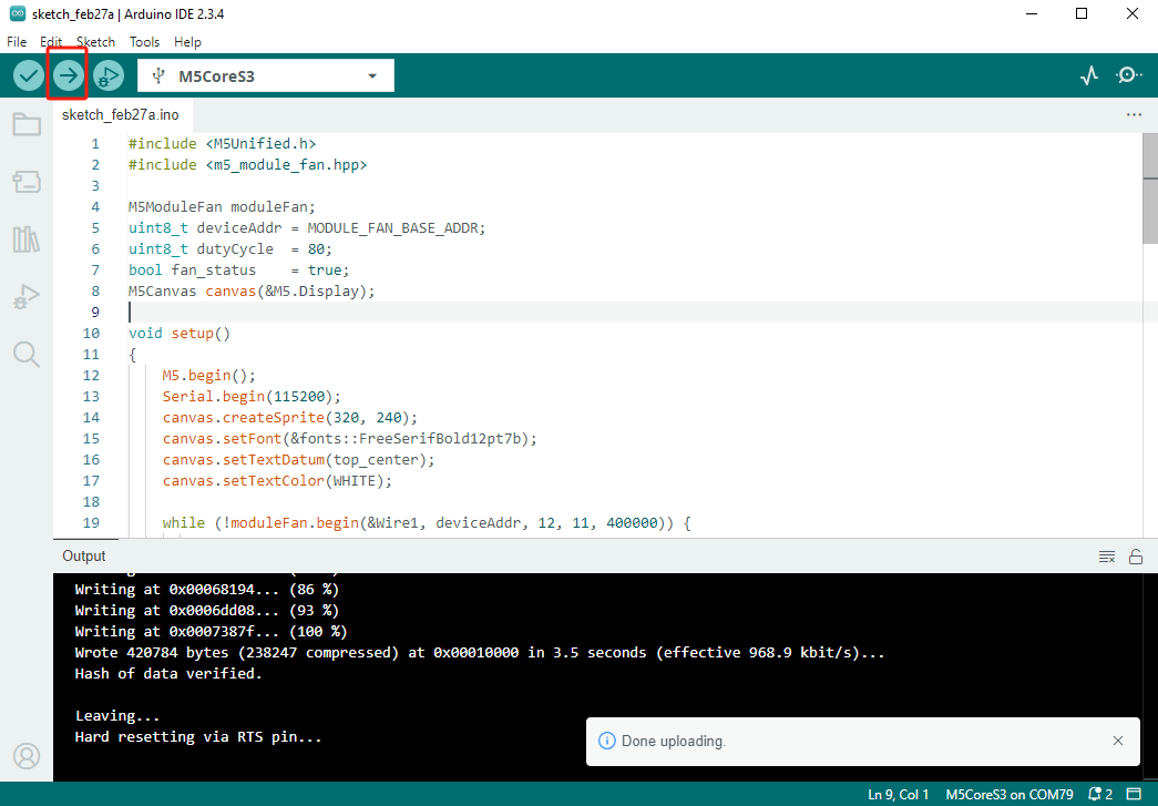
CoreS3 の場合:リセットボタンを約2秒間長押しし、内部の緑色 LED が点灯したら離します。これでデバイスはダウンロードモードに入り、プログラミングを待機します。
.gif)
- デバイスポートを選択し、Arduino IDE の左上にあるアップロードボタンをクリックします。プログラムのコンパイルが完了し、デバイスにアップロードされるのを待ちます。