Arduino Quick Start
2. Devices & Examples
3. M5Unified
4. M5GFX
5. Extensions
Unit
Atomic
Tab5
IoT
Accessories
Base Dual 16340 Arduino Tutorial
1. Preparation
1. Environment setup: Refer to the Arduino IDE Getting Started Tutorial to complete IDE installation, then install the corresponding board manager and required driver libraries according to the development board you are using.
2. Driver libraries used:
Library Note
M5GFX is already included as a dependency of M5Unified. In most cases, you only need to install M5Unified. If the compiler reports that M5GFX is missing, install it separately.
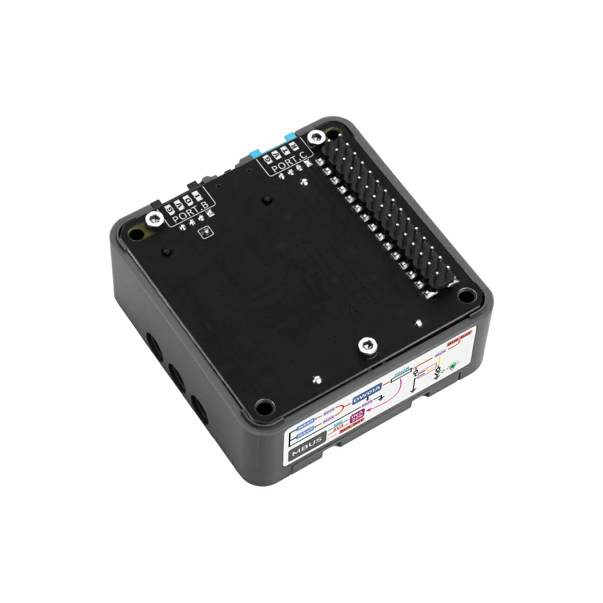
- 3. Hardware products used:

2. Notes
Battery Installation and Power Supply
First confirm that the positive and negative terminals of both 16340 batteries are installed correctly, then switch the base toggle switch to
ON. Although the base includes a protection circuit, frequent battery insertion and removal while powered on is not recommended.Pin Compatibility
Since each host has a different pin configuration, refer to the Pin Compatibility Table in the product documentation before use, and modify the example program according to the actual pin connection.
3. Example Program
- The main controller used in this tutorial is CoreS3 with Base Dual 16340. The onboard INA226 on the base communicates with the controller through the internal I2C bus. Referring to the stacked pin definition between CoreS3 and the base, the I2C pins used in the example are
G12 (SDA)andG11 (SCL).
cpp
1 2 3 4 5 6 7 8 9 10 11 12 13 14 15 16 17 18 19 20 21 22 23 24 25 26 27 28 29 30 31 32 33 34 35 36 37 38 39 40 41 42 43 44 45 46 47 48 49 50 51 52 53 54 55 56 57 58 59 60 61 62 63 64 65 66 67 68 69 70 71 72 73 74 75 76 77 78 79 80 81 82
#include "M5Unified.h"

// INA226 current/voltage monitor on internal I2C bus(M5.In_I2C)
// INA226 I2C address: 0x45
m5::INA226_Class Ina226(0x45);
bool ina226Ready = false;

void setup()
{
    auto cfg = M5.config();
    M5.begin(cfg);
    M5.Display.setFont(&fonts::FreeMonoBold9pt7b);

    // Initialize INA226 at I2C address 0x45
    if (Ina226.begin()) {
        ina226Ready = true;
        M5.Display.setCursor(10, 10);
        M5.Display.print("INA226 found!");

        // Configure INA226 measurement parameters
        m5::INA226_Class::config_t ina_cfg;

        // Shunt resistor value: 20mΩ (Fixed value for Base Dual 16340)
        ina_cfg.shunt_res = 0.02f;
        // Maximum expected current: 3A — used by the chip to set the calibration register
        ina_cfg.max_expected_current = 3.0f;
        // Operating mode: continuous measurement of both bus voltage and shunt voltage
        ina_cfg.mode = m5::INA226_Class::Mode::ShuntAndBus;
        // ADC sampling rate: average 16 samples per reading for noise reduction
        ina_cfg.sampling_rate = m5::INA226_Class::Sampling::Rate16;
        // Bus voltage conversion time: 1.1 ms per sample
        ina_cfg.bus_conversion_time = m5::INA226_Class::ConversionTime::US_1100;
        // Shunt voltage conversion time: 1.1 ms per sample
        ina_cfg.shunt_conversion_time = m5::INA226_Class::ConversionTime::US_1100;
        // Apply all configuration settings to the INA226
        Ina226.config(ina_cfg);
    } else {
        M5.Display.setCursor(10, 10);
        M5.Display.print("INA226 not found!");
    }
}

void loop()
{
    M5.update();
    M5.Display.clear();

    if (!ina226Ready) {
        M5.Display.setCursor(10, 10);
        M5.Display.print("INA226 not found!");
        delay(1000);
        return;
    }

    // VBUS is wired to BUS_BAT, so this is the battery output bus voltage.
    float batteryVoltage_V = Ina226.getBusVoltage();
    float batteryVoltage_mV = batteryVoltage_V * 1000.0f;
    M5.Display.setCursor(10, 10);
    M5.Display.printf("Battery Voltage: %.0fmV", batteryVoltage_mV);

    // Current through the shunt resistor is the battery current if no bypass path exists.
    float batteryCurrent_A = Ina226.getShuntCurrent();
    float batteryCurrent_mA = batteryCurrent_A * 1000.0f;
    M5.Display.setCursor(10, 40);
    M5.Display.printf("Battery Current: %.1fmA", batteryCurrent_mA);

    // Voltage drop across the 20mΩ shunt resistor.
    float shuntVoltage_mV = Ina226.getShuntVoltage() * 1000.0f;
    M5.Display.setCursor(10, 70);
    M5.Display.printf("Shunt Voltage: %.3fmV", shuntVoltage_mV);

    float shuntCurrent_mA = batteryCurrent_mA;
    M5.Display.setCursor(10, 100);
    M5.Display.printf("Shunt Current: %.1fmA", shuntCurrent_mA);

    // INA226 calculates power from bus voltage and calibrated shunt current.
    float batteryPower_mW = Ina226.getPower() * 1000.0f;
    M5.Display.setCursor(10, 130);
    M5.Display.printf("Battery Power: %.1fmW", batteryPower_mW);

    delay(1000);
}4. Compile and Upload
- 1. Enter download mode: Press and hold the CoreS3 reset button for about 2 seconds until the internal green LED lights up, then release it. The device has now entered download mode and is ready for flashing.
Note
Different devices need to enter download mode before flashing a program, and this step may vary between host devices. For details, refer to the device program download tutorial list at the bottom of the Arduino IDE Getting Started Tutorial page to see the specific operation method.
.gif)
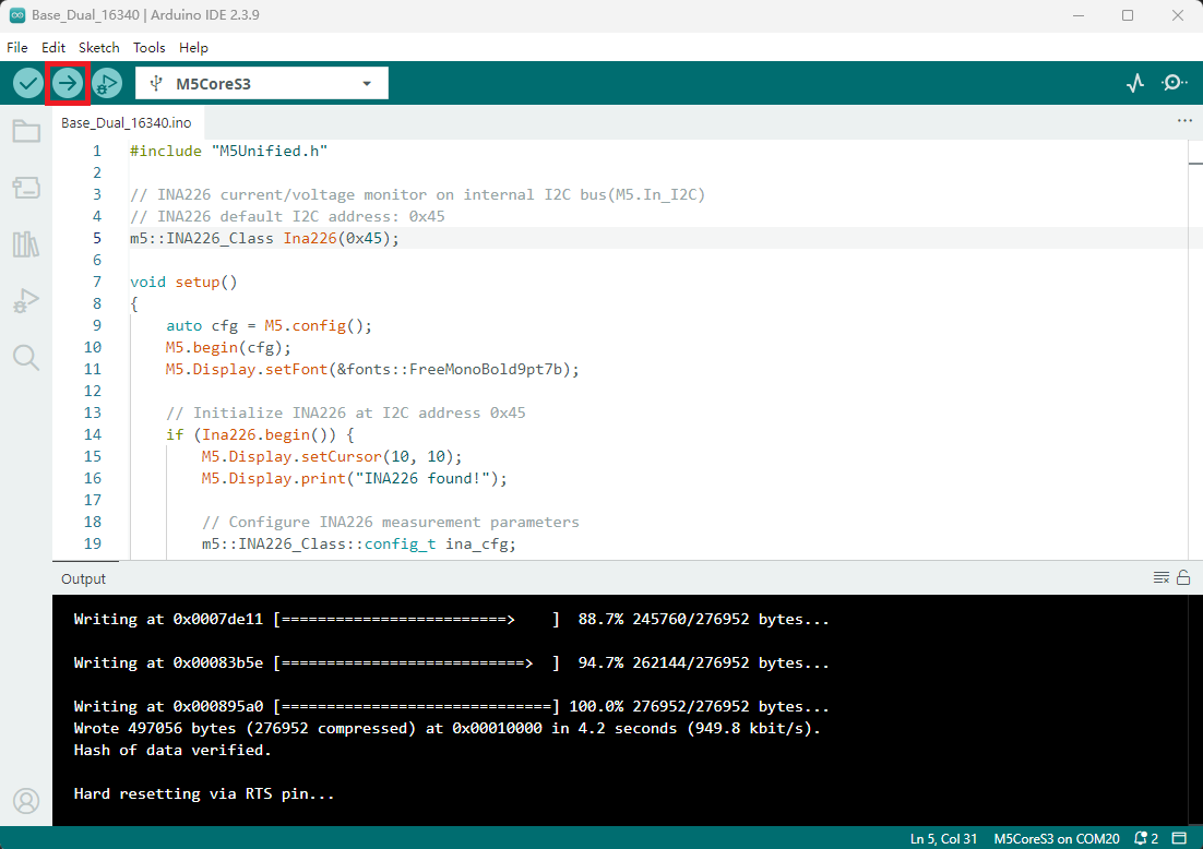
- 2. Select the device port, click the compile and upload button in the upper-left corner of Arduino IDE, and wait for the program to finish compiling and uploading to the device.
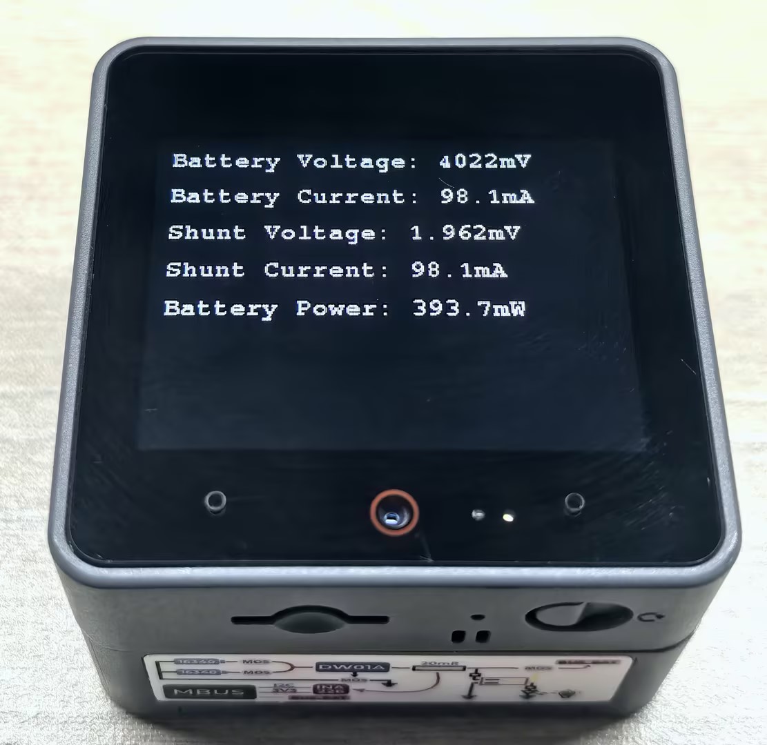
5. Battery Monitoring Effect
After the program is uploaded successfully, the controller screen will continuously display real-time battery voltage, current, power, and other information, making it convenient to monitor the battery usage status.