

Arduino Quick Start
2. Devices & Examples
3. M5Unified
4. M5GFX
5. Extensions
Unit
Atomic
Tab5
IoT
Accessories
Unit 4Relay Arduino Tutorial
1. Preparation
- Environment Setup: Refer to the Arduino IDE Getting Started Guide to complete the IDE installation, and install the corresponding board manager and required driver libraries according to the development board you are using.
- Libraries Used:
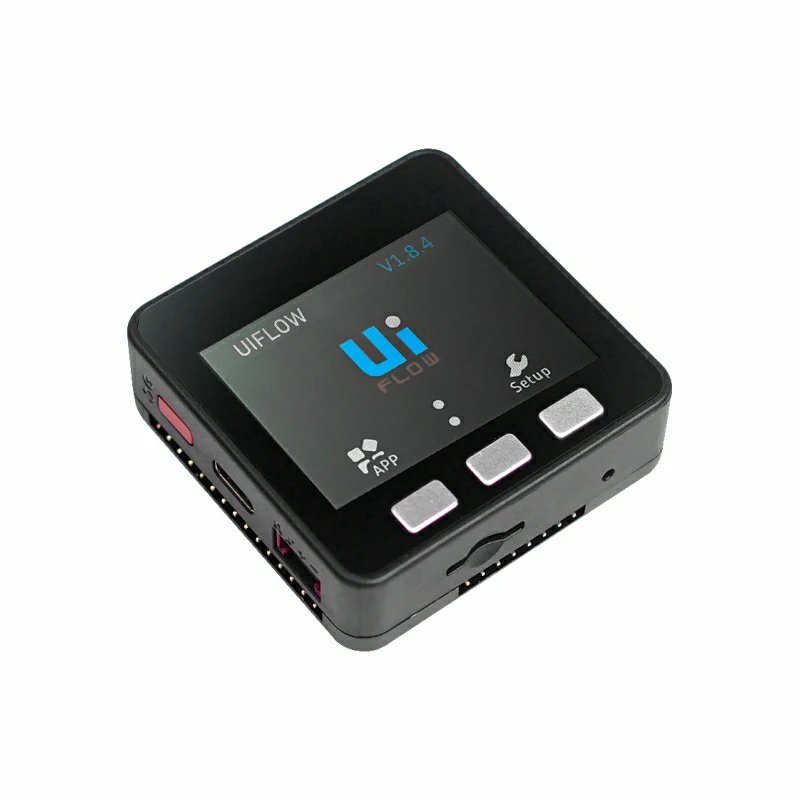
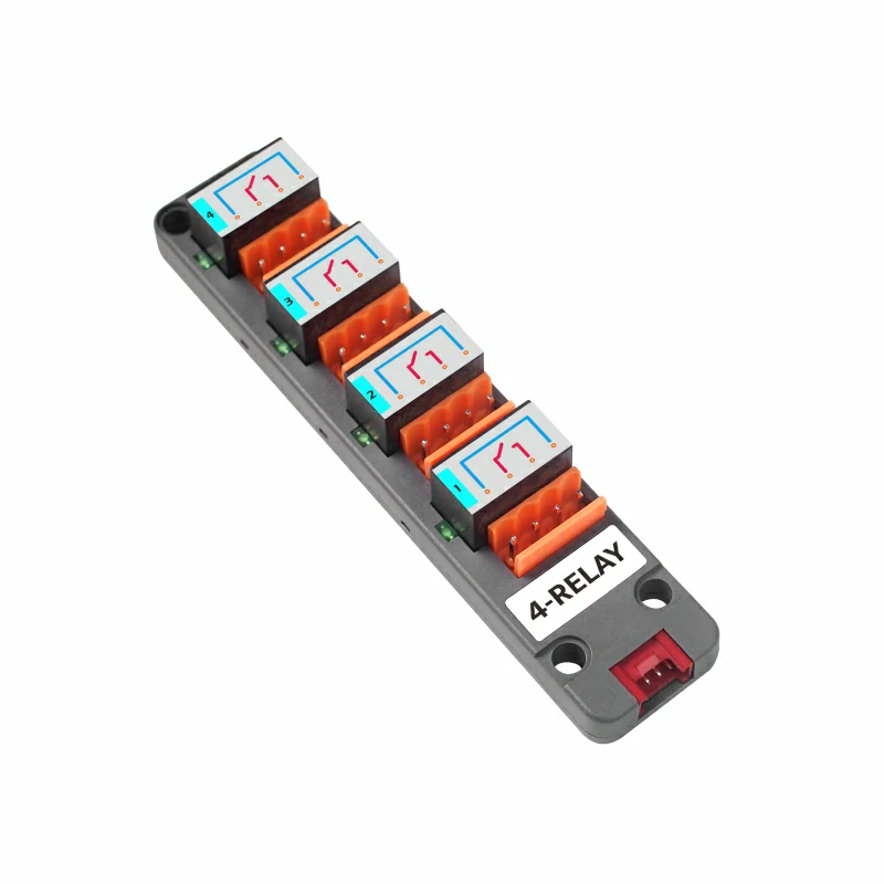
- Hardware Products Used:
2. Notes
Pin Compatibility
Because each host has a different pin configuration, M5Stack provides an official pin compatibility table for convenient reference. Please modify the example program according to the actual pin connections.
3. Example
- This tutorial uses a Basic V2.7 as the main controller with a Unit 4Relay. This relay module communicates via I2C. Modify the pin definitions in the program according to the actual circuit connection; the connected pins are
G21(SDA)andG22(SCL).
Note
This module can control the relays only in synchronous mode. Controlling the relays in asynchronous mode has no effect; only the LED indicators can be controlled.
cpp
1 2 3 4 5 6 7 8 9 10 11 12 13 14 15 16 17 18 19 20 21 22 23 24 25 26 27 28 29 30 31 32 33 34 35 36 37 38 39 40 41 42 43 44 45 46 47 48 49 50 51 52 53 54 55 56 57 58 59 60 61 62 63 64 65 66 67 68 69 70 71 72 73 74 75 76 77 78 79 80 81 82 83 84 85 86 87 88 89 90 91 92 93 94 95 96 97 98 99 100 101 102 103 104 105 106 107 108 109 110 111 112 113 114 115 116 117 118 119 120 121 122 123 124 125 126 127 128 129 130 131 132 133 134 135 136 137 138 139 140 141 142 143 144 145 146 147 148 149 150 151 152 153 154 155 156 157 158 159 160 161 162 163 164 165 166 167 168 169 170 171 172 173 174 175 176 177 178 179 180 181 182 183 184 185 186 187 188 189 190 191 192 193 194 195 196
#include <M5Unified.h>
#include "Unit_4RELAY.h"

UNIT_4RELAY relay;

namespace {
constexpr uint16_t COLOR_BG      = 0x1082;
constexpr uint16_t COLOR_SURFACE = 0x2104;
constexpr uint16_t COLOR_HEADER  = 0x0349;
constexpr uint16_t COLOR_BORDER  = 0x52AA;
constexpr uint16_t COLOR_MUTED   = 0xBDF7;
constexpr uint16_t COLOR_GREEN   = 0x2E8B;
constexpr uint16_t COLOR_RED     = 0xD249;
constexpr uint16_t COLOR_AMBER   = 0xFD20;

constexpr int16_t CHANNEL_Y      = 148;
constexpr int16_t CHANNEL_WIDTH  = 68;
constexpr int16_t CHANNEL_HEIGHT = 43;
constexpr int16_t CHANNEL_GAP    = 8;

uint8_t stepIndex = 0;
bool syncMode     = false;
bool allOn        = false;
bool relayState[4] = {false, false, false, false};
bool ledState[4]   = {false, false, false, false};

void drawModeStatus()
{
    M5.Display.fillRect(0, 38, 320, 36, COLOR_BG);
    M5.Display.setFont(&fonts::Font2);
    M5.Display.setTextDatum(textdatum_t::middle_left);
    M5.Display.setTextColor(COLOR_MUTED, COLOR_BG);
    M5.Display.drawString("MODE", 12, 56);
    M5.Display.drawString("CONTROL", 161, 56);

    const uint16_t modeColor = syncMode ? COLOR_GREEN : COLOR_AMBER;
    M5.Display.fillRoundRect(57, 44, 82, 25, 4, modeColor);
    M5.Display.fillRoundRect(231, 44, 77, 25, 4, COLOR_SURFACE);
    M5.Display.drawRoundRect(231, 44, 77, 25, 4, COLOR_BORDER);

    M5.Display.setTextDatum(textdatum_t::middle_center);
    M5.Display.setTextColor(TFT_BLACK, modeColor);
    M5.Display.drawString(syncMode ? "SYNC" : "ASYNC", 98, 56);
    M5.Display.setTextColor(TFT_WHITE, COLOR_SURFACE);
    M5.Display.drawString(syncMode ? "RELAY" : "LED", 269, 56);
}

void drawAction(const char *message)
{
    M5.Display.fillRoundRect(10, 81, 300, 38, 4, COLOR_SURFACE);
    M5.Display.drawRoundRect(10, 81, 300, 38, 4, COLOR_BORDER);
    M5.Display.setFont(&fonts::Font2);
    M5.Display.setTextDatum(textdatum_t::middle_left);
    M5.Display.setTextColor(COLOR_MUTED, COLOR_SURFACE);
    M5.Display.drawString("LAST ACTION", 20, 100);
    M5.Display.setTextColor(TFT_WHITE, COLOR_SURFACE);
    M5.Display.drawString(message, 119, 100);
}

void drawChannel(uint8_t channel)
{
    const bool isOn       = syncMode ? relayState[channel] : ledState[channel];
    const uint16_t color  = isOn ? COLOR_GREEN : COLOR_BORDER;
    const int16_t x       = 10 + channel * (CHANNEL_WIDTH + CHANNEL_GAP);
    char channelLabel[5]  = {};
    snprintf(channelLabel, sizeof(channelLabel), "CH%u",
             static_cast<unsigned>(channel + 1));

    M5.Display.fillRoundRect(x, CHANNEL_Y, CHANNEL_WIDTH, CHANNEL_HEIGHT, 4,
                             COLOR_SURFACE);
    M5.Display.drawRoundRect(x, CHANNEL_Y, CHANNEL_WIDTH, CHANNEL_HEIGHT, 4,
                             color);
    M5.Display.setTextDatum(textdatum_t::middle_center);
    M5.Display.setFont(&fonts::Font2);
    M5.Display.setTextColor(COLOR_MUTED, COLOR_SURFACE);
    M5.Display.drawString(channelLabel, x + CHANNEL_WIDTH / 2, CHANNEL_Y + 12);
    M5.Display.setTextColor(isOn ? COLOR_GREEN : TFT_WHITE, COLOR_SURFACE);
    M5.Display.drawString(isOn ? "ON" : "OFF", x + CHANNEL_WIDTH / 2,
                          CHANNEL_Y + 31);
}

void drawAllChannels()
{
    M5.Display.fillRect(0, 125, 320, 22, COLOR_BG);
    M5.Display.setFont(&fonts::Font2);
    M5.Display.setTextDatum(textdatum_t::middle_left);
    M5.Display.setTextColor(COLOR_MUTED, COLOR_BG);
    M5.Display.drawString(syncMode ? "RELAY STATUS" : "LED STATUS", 10, 136);

    for (uint8_t channel = 0; channel < 4; ++channel) {
        drawChannel(channel);
    }
}

void drawButtonHint(int16_t x, char button, const char *label, uint16_t color)
{
    char buttonLabel[2] = {button, '\0'};

    M5.Display.fillCircle(x, 220, 11, color);
    M5.Display.setFont(&fonts::Font2);
    M5.Display.setTextDatum(textdatum_t::middle_center);
    M5.Display.setTextColor(TFT_BLACK, color);
    M5.Display.drawString(buttonLabel, x, 220);
    M5.Display.setTextDatum(textdatum_t::middle_left);
    M5.Display.setTextColor(TFT_WHITE, COLOR_SURFACE);
    M5.Display.drawString(label, x + 16, 220);
}

void drawMainUi()
{
    M5.Display.fillScreen(COLOR_BG);
    M5.Display.fillRect(0, 0, 320, 34, COLOR_HEADER);
    M5.Display.setFont(&fonts::Font4);
    M5.Display.setTextDatum(textdatum_t::middle_center);
    M5.Display.setTextColor(TFT_WHITE, COLOR_HEADER);
    M5.Display.drawString("UNIT 4RELAY", 160, 17);

    drawModeStatus();
    drawAction("Ready");
    drawAllChannels();

    M5.Display.fillRect(0, 202, 320, 38, COLOR_SURFACE);
    M5.Display.drawFastHLine(0, 202, 320, COLOR_BORDER);
    drawButtonHint(15, 'A', "STEP", COLOR_GREEN);
    drawButtonHint(121, 'B', "MODE", COLOR_AMBER);
    drawButtonHint(229, 'C', "ALL", COLOR_RED);
}

void updateStateAfterAllWrite(bool state)
{
    // relayAll() and ledAll() overwrite the complete output register.
    for (uint8_t channel = 0; channel < 4; ++channel) {
        relayState[channel] = syncMode ? state : false;
        ledState[channel]   = syncMode ? false : state;
    }
}
}  // namespace

void setup()
{
    M5.begin();
    Serial.begin(115200);

    M5.Display.setRotation(1);
    relay.begin(&Wire, 21, 22);
    relay.Init(false);  // Start in asynchronous mode with all outputs off.
    drawMainUi();
}

void loop()
{
    M5.update();

    if (M5.BtnA.wasPressed()) {
        const uint8_t channel = stepIndex % 4;
        const bool state      = stepIndex < 4;
        char message[20]      = {};

        if (syncMode) {
            relay.relayWrite(channel, state);
            relayState[channel] = state;
        } else {
            relay.ledWrite(channel, state);
            ledState[channel] = state;
        }

        snprintf(message, sizeof(message), "%s %u  %s",
                 syncMode ? "Relay" : "LED",
                 static_cast<unsigned>(channel + 1),
                 state ? "ON" : "OFF");
        drawAction(message);
        drawChannel(channel);
        stepIndex = (stepIndex + 1) % 8;
    }

    if (M5.BtnB.wasPressed()) {
        syncMode = !syncMode;
        relay.switchMode(syncMode);
        drawModeStatus();
        drawAction(syncMode ? "Sync mode enabled" : "Async mode enabled");
        drawAllChannels();
    }

    if (M5.BtnC.wasPressed()) {
        allOn = !allOn;
        if (syncMode) {
            relay.relayAll(allOn);
        } else {
            relay.ledAll(allOn);
        }

        updateStateAfterAllWrite(allOn);
        drawAction(allOn ? "All channels ON" : "All channels OFF");
        drawAllChannels();
    }
}4. Compile and Upload
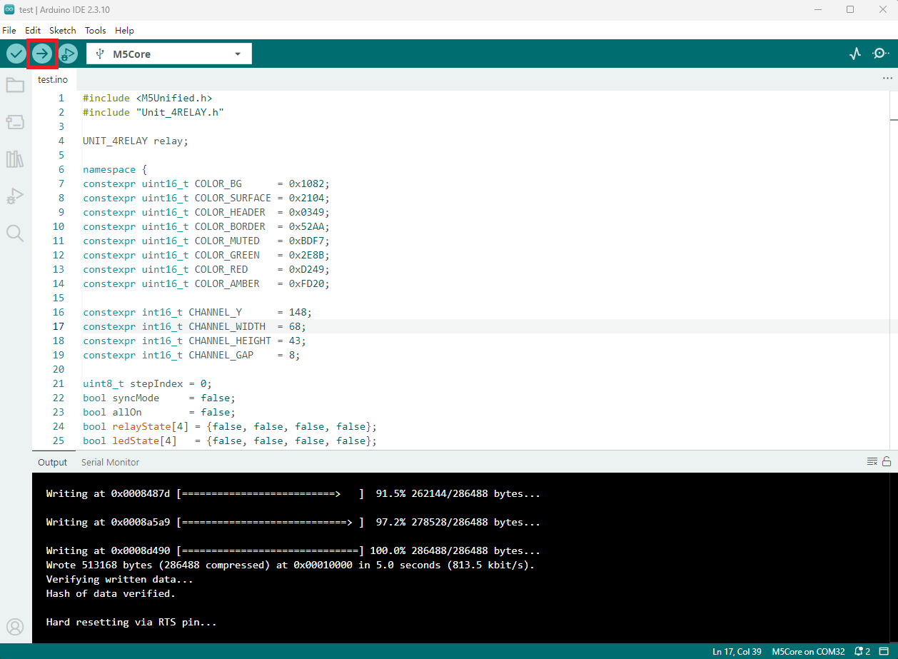
- Copy and paste the example code above into the project code area, select the device port (for details, refer to Compile and Upload the Program), click the compile and upload button in the upper-left corner of the Arduino IDE, and wait for the program to compile and upload to the device.
5. Relay Control
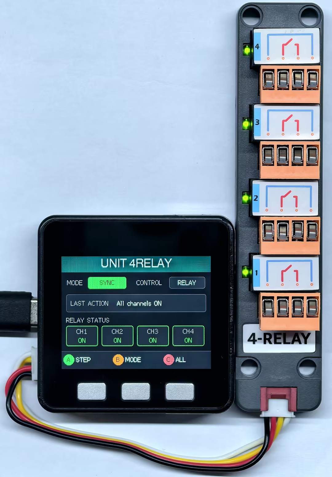
- Button A controls individual relays, button B switches between synchronous and asynchronous modes for the LEDs and relays, and button C turns all relays and LED indicators on or off.
Page Tools