

Arduino Quick Start
2. Devices & Examples
3. M5Unified
4. M5GFX
5. Extensions
Unit
Module
Atomic
Tab5
IoT
Accessories
Unit 2Relay Arduino Tutorial
1. Preparation
- Environment Setup: Follow the Arduino IDE Getting Started Guide to complete the IDE installation, and install the corresponding board manager and driver libraries according to the development board you are using.
- Libraries Used:
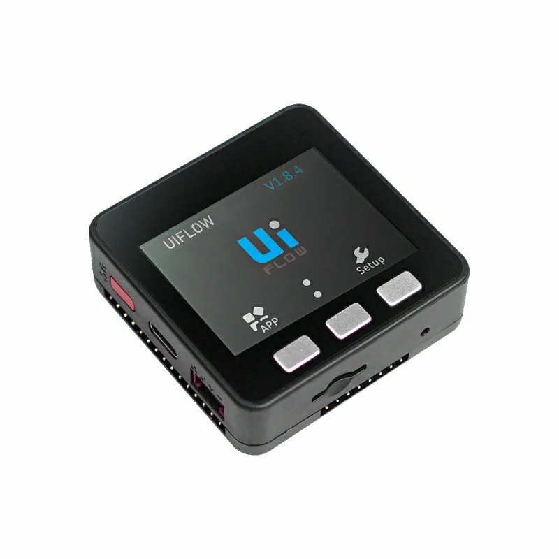
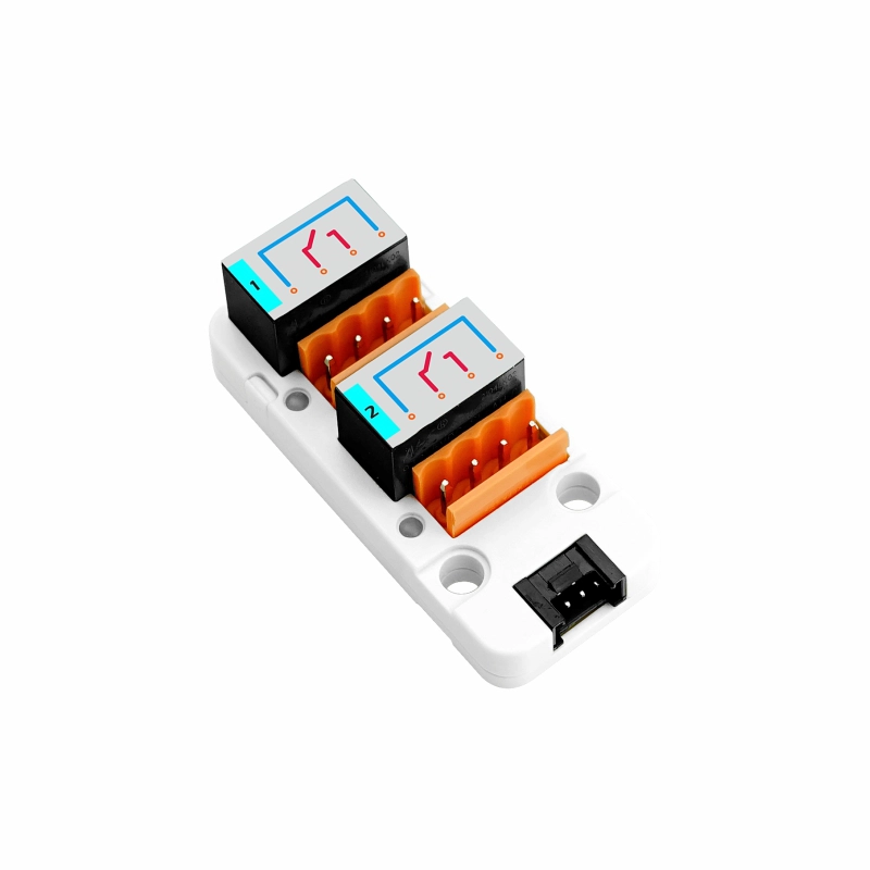
- Hardware Products Used:
2. Notes
Pin Compatibility
Because each host has a different pin configuration, M5Stack provides an official pin compatibility table for convenient reference. Please modify the example program according to the actual pin connections.
3. Example
- This tutorial uses a Basic V2.7 with a Unit 2Relay, with the module connected to Port A. Unit 2Relay is controlled directly through GPIO HIGH/LOW levels. RELAY-1 corresponds to
G22on the Basic V2.7, and RELAY-2 corresponds toG21. When the output is HIGH, the corresponding relay is energized and its status indicator lights up; when the output is LOW, the relay is released.
cpp
1 2 3 4 5 6 7 8 9 10 11 12 13 14 15 16 17 18 19 20 21 22 23 24 25 26 27 28 29 30 31 32 33 34 35 36 37 38 39 40 41 42 43 44 45 46 47 48 49 50 51 52 53 54 55 56 57 58 59 60 61 62 63 64 65 66 67 68 69 70 71 72 73 74 75 76 77 78 79 80 81 82 83 84 85 86 87 88 89 90 91 92 93 94 95 96 97 98 99 100 101 102 103 104 105 106 107 108 109 110 111 112 113 114 115 116 117 118 119 120 121 122 123 124 125 126 127 128 129 130 131 132 133 134 135 136 137 138 139 140 141 142 143 144 145 146 147 148 149 150 151 152 153 154 155 156 157 158 159 160 161 162 163 164 165 166 167 168 169 170 171 172
#include <M5Unified.h>

namespace {
constexpr uint16_t COLOR_BG      = 0x1082;
constexpr uint16_t COLOR_SURFACE = 0x2104;
constexpr uint16_t COLOR_HEADER  = 0x0349;
constexpr uint16_t COLOR_BORDER  = 0x52AA;
constexpr uint16_t COLOR_MUTED   = 0xBDF7;
constexpr uint16_t COLOR_GREEN   = 0x2E8B;
constexpr uint16_t COLOR_RED     = 0xD249;

constexpr int16_t CHANNEL_Y       = 148;
constexpr int16_t CHANNEL_WIDTH   = 100;
constexpr int16_t CHANNEL_HEIGHT  = 43;
constexpr int16_t CHANNEL_GAP     = 20;
constexpr int16_t CHANNEL_START_X = 50;

int relayPins[2]   = {-1, -1};
bool relayState[2] = {false, false};
uint8_t stepIndex  = 0;

void drawControlStatus()
{
    M5.Display.fillRect(0, 38, 320, 36, COLOR_BG);
    M5.Display.setFont(&fonts::Font2);
    M5.Display.setTextDatum(textdatum_t::middle_left);
    M5.Display.setTextColor(COLOR_MUTED, COLOR_BG);
    M5.Display.drawString("CONTROL", 12, 56);
    M5.Display.drawString("CHANNELS", 174, 56);

    M5.Display.fillRoundRect(82, 44, 70, 25, 4, COLOR_GREEN);
    M5.Display.fillRoundRect(258, 44, 50, 25, 4, COLOR_SURFACE);
    M5.Display.drawRoundRect(258, 44, 50, 25, 4, COLOR_BORDER);

    M5.Display.setTextDatum(textdatum_t::middle_center);
    M5.Display.setTextColor(TFT_BLACK, COLOR_GREEN);
    M5.Display.drawString("GPIO", 117, 56);
    M5.Display.setTextColor(TFT_WHITE, COLOR_SURFACE);
    M5.Display.drawString("2", 283, 56);
}

void drawAction(const char *message)
{
    M5.Display.fillRoundRect(10, 81, 300, 38, 4, COLOR_SURFACE);
    M5.Display.drawRoundRect(10, 81, 300, 38, 4, COLOR_BORDER);
    M5.Display.setFont(&fonts::Font2);
    M5.Display.setTextDatum(textdatum_t::middle_left);
    M5.Display.setTextColor(COLOR_MUTED, COLOR_SURFACE);
    M5.Display.drawString("LAST ACTION", 20, 100);
    M5.Display.setTextColor(TFT_WHITE, COLOR_SURFACE);
    M5.Display.drawString(message, 119, 100);
}

void drawChannel(uint8_t channel)
{
    const bool isOn      = relayState[channel];
    const uint16_t color = isOn ? COLOR_GREEN : COLOR_BORDER;
    const int16_t x = CHANNEL_START_X + channel * (CHANNEL_WIDTH + CHANNEL_GAP);
    char channelLabel[5] = {};
    snprintf(channelLabel, sizeof(channelLabel), "CH%u",
             static_cast<unsigned>(channel + 1));

    M5.Display.fillRoundRect(x, CHANNEL_Y, CHANNEL_WIDTH, CHANNEL_HEIGHT, 4,
                             COLOR_SURFACE);
    M5.Display.drawRoundRect(x, CHANNEL_Y, CHANNEL_WIDTH, CHANNEL_HEIGHT, 4,
                             color);
    M5.Display.setTextDatum(textdatum_t::middle_center);
    M5.Display.setFont(&fonts::Font2);
    M5.Display.setTextColor(COLOR_MUTED, COLOR_SURFACE);
    M5.Display.drawString(channelLabel, x + CHANNEL_WIDTH / 2, CHANNEL_Y + 12);
    M5.Display.setTextColor(isOn ? COLOR_GREEN : TFT_WHITE, COLOR_SURFACE);
    M5.Display.drawString(isOn ? "ON" : "OFF", x + CHANNEL_WIDTH / 2,
                          CHANNEL_Y + 31);
}

void drawAllChannels()
{
    M5.Display.fillRect(0, 125, 320, 22, COLOR_BG);
    M5.Display.setFont(&fonts::Font2);
    M5.Display.setTextDatum(textdatum_t::middle_left);
    M5.Display.setTextColor(COLOR_MUTED, COLOR_BG);
    M5.Display.drawString("RELAY STATUS", 10, 136);

    for (uint8_t channel = 0; channel < 2; ++channel) {
        drawChannel(channel);
    }
}

void drawButtonHint(int16_t x, char button, const char *label, uint16_t color)
{
    char buttonLabel[2] = {button, '\0'};

    M5.Display.fillCircle(x, 220, 11, color);
    M5.Display.setFont(&fonts::Font2);
    M5.Display.setTextDatum(textdatum_t::middle_center);
    M5.Display.setTextColor(TFT_BLACK, color);
    M5.Display.drawString(buttonLabel, x, 220);
    M5.Display.setTextDatum(textdatum_t::middle_left);
    M5.Display.setTextColor(TFT_WHITE, COLOR_SURFACE);
    M5.Display.drawString(label, x + 16, 220);
}

void drawMainUi()
{
    M5.Display.fillScreen(COLOR_BG);
    M5.Display.fillRect(0, 0, 320, 34, COLOR_HEADER);
    M5.Display.setFont(&fonts::Font4);
    M5.Display.setTextDatum(textdatum_t::middle_center);
    M5.Display.setTextColor(TFT_WHITE, COLOR_HEADER);
    M5.Display.drawString("UNIT 2RELAY", 160, 17);

    drawControlStatus();
    drawAction("Ready");
    drawAllChannels();

    M5.Display.fillRect(0, 202, 320, 38, COLOR_SURFACE);
    M5.Display.drawFastHLine(0, 202, 320, COLOR_BORDER);
    drawButtonHint(48, 'A', "STEP", COLOR_GREEN);
    drawButtonHint(210, 'C', "ALL", COLOR_RED);
}

void writeRelay(uint8_t channel, bool state)
{
    digitalWrite(relayPins[channel], state ? HIGH : LOW);
    relayState[channel] = state;
}
}  // namespace

void setup()
{
    M5.begin();
    Serial.begin(115200);
    M5.Display.setRotation(1);

    // Grove Port A: white wire controls RELAY-1, yellow wire controls RELAY-2.
    relayPins[0] = M5.getPin(m5::pin_name_t::port_a_pin2);
    relayPins[1] = M5.getPin(m5::pin_name_t::port_a_pin1);
    for (uint8_t channel = 0; channel < 2; ++channel) {
        pinMode(relayPins[channel], OUTPUT);
        writeRelay(channel, false);
    }

    drawMainUi();
}

void loop()
{
    M5.update();

    if (M5.BtnA.wasPressed()) {
        const uint8_t channel = stepIndex % 2;
        const bool state      = stepIndex < 2;
        char message[20]      = {};

        writeRelay(channel, state);
        snprintf(message, sizeof(message), "Relay %u  %s",
                 static_cast<unsigned>(channel + 1), state ? "ON" : "OFF");
        drawAction(message);
        drawChannel(channel);
        stepIndex = (stepIndex + 1) % 4;
    }

    if (M5.BtnC.wasPressed()) {
        const bool state = !(relayState[0] && relayState[1]);
        for (uint8_t channel = 0; channel < 2; ++channel) {
            writeRelay(channel, state);
        }

        drawAction(state ? "All channels ON" : "All channels OFF");
        drawAllChannels();
    }
}4. Compile and Upload
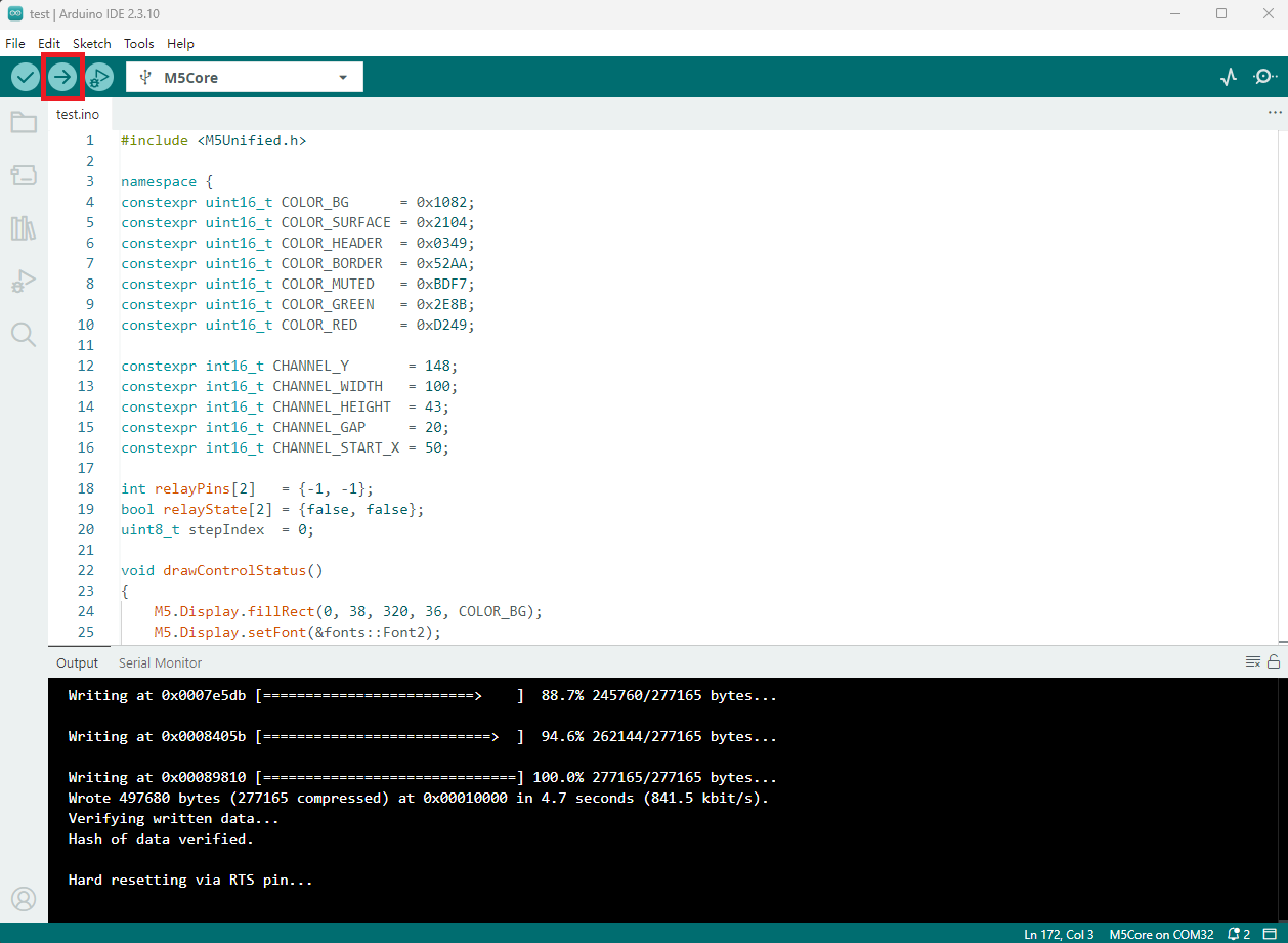
- Copy and paste the example code above into the project code area, select the device port (for details, refer to Compile and Upload the Program), click the compile and upload button in the upper-left corner of the Arduino IDE, and wait for the program to compile and upload to the device.
5. Relay Control
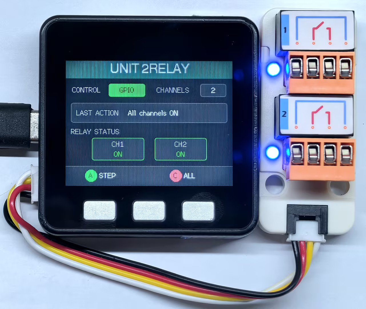
- Press button A to cycle the two relays through
CH1 ON → CH2 ON → CH1 OFF → CH2 OFF; press button C to turn on all relays if they are not all currently on, or turn off all relays if both are already on. TheCH1,CH2, andLAST ACTIONareas on the screen update to show the current control result.
Page Tools