

Arduino Quick Start
2. Devices & Examples
3. M5Unified
4. M5GFX
5. Extensions
Unit
Atomic
Tab5
IoT
Accessories
Chain PIR Tutorial
1.Preparation
- Environment Setup: Refer to the Arduino IDE Getting Started Guide to install the IDE, then install the appropriate board package and required driver libraries for the development board you are using.
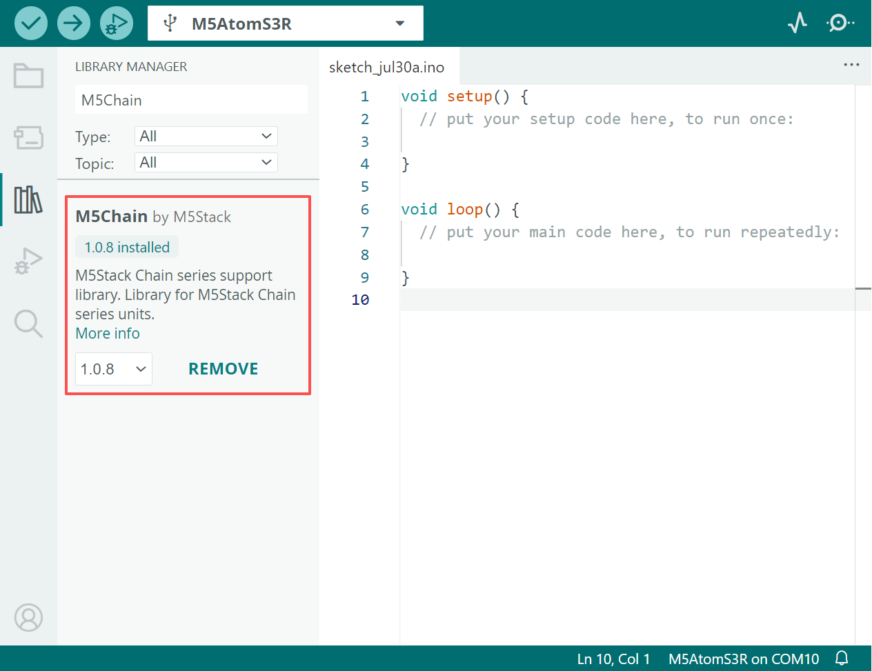
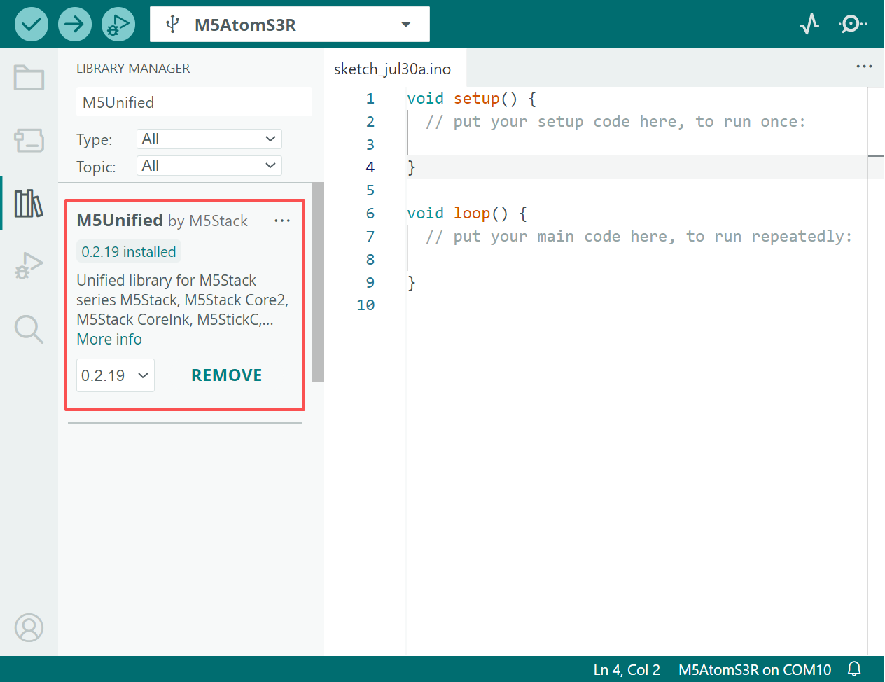
- Required Driver Libraries:
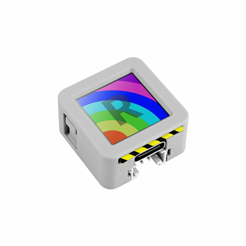
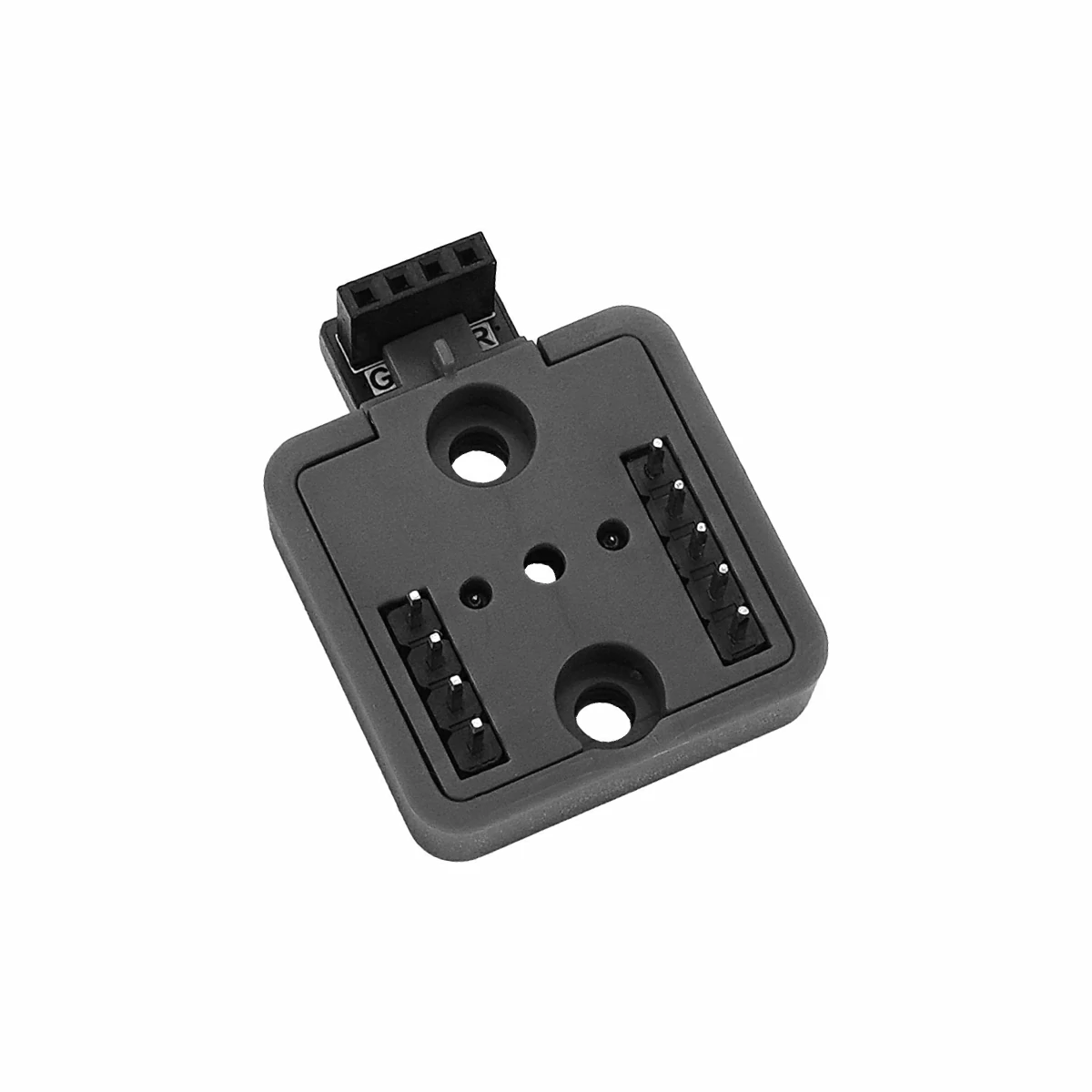
- Required Hardware Products:
- AtomS3R
- Atomic toChain Base
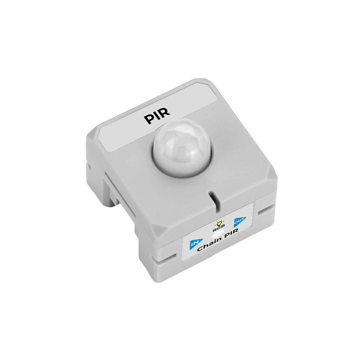
- [**Chain PIR**]( Link TBD )
2.Example Program
M5Chain Library Version >= 1.0.8
M5Unified Library Version >= 0.2.18
Use the Atomic toChain Base to connect the AtomS3R controller to Chain PIR. Make sure the orientation is correct: the triangular arrow should point outward from the AtomS3R controller, as shown below:
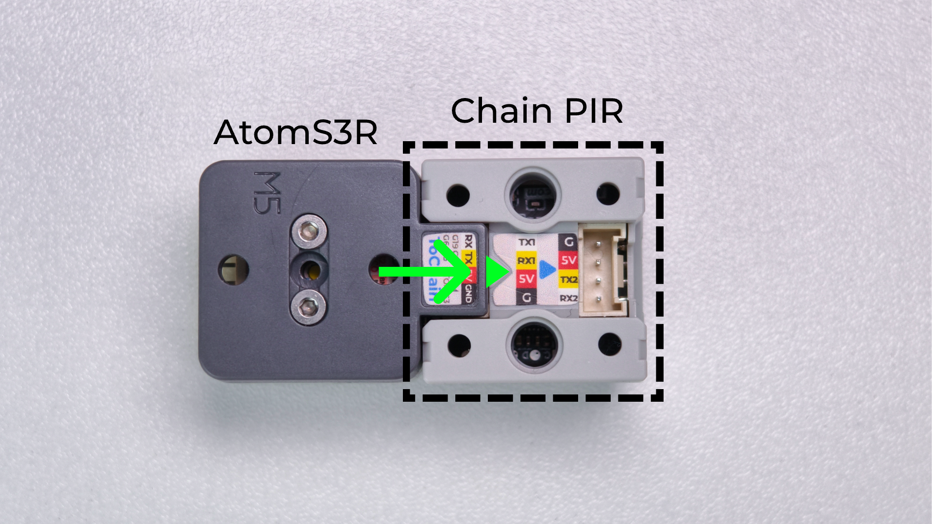
TXD_PIN = GPIO_NUM_5 (GPIO5)
This example uses GPIO6 on AtomS3R as RX and GPIO5 as TX. If you use a different controller, update RXD_PIN and TXD_PIN in the program according to the actual wiring.
2.1 Event Trigger Mode
In event trigger mode, the program first enables unsolicited reports using setPIRDetectTriggerMode(). It then stops polling the PIR status and only receives entry and exit events reported by Chain PIR.
#include <M5Chain.h>
#include <M5Unified.h>

#define RXD_PIN GPIO_NUM_6  // AtomS3R RX
#define TXD_PIN GPIO_NUM_5  // AtomS3R TX

// Maximum number of devices handled by this demo.
constexpr uint8_t MAX_DEVICES = 16;

Chain M5Chain;
uint8_t pir_id = 0;

void showStatus(const char *text, uint16_t color)
{
    // Show one centered status message on the AtomS3R display.
    M5.Display.fillScreen(0x0000);
    M5.Display.setTextDatum(middle_center);
    M5.Display.setTextColor(color);
    M5.Display.setTextSize(2);
    M5.Display.drawString(text, 64, 64);
}

void showModeStatus(const char *mode, const char *status, uint16_t color)
{
    // Keep the operating mode visible above the current PIR state.
    M5.Display.fillScreen(0x0000);
    M5.Display.setTextDatum(middle_center);
    M5.Display.setTextColor(color);
    M5.Display.setTextSize(2);
    M5.Display.drawString(mode, 64, 43);
    M5.Display.drawString(status, 64, 78);
}

bool findPIR()
{
    // Enumerate the Chain bus and select the first PIR device.
    uint16_t device_count = 0;
    if (!M5Chain.isDeviceConnected() ||
        M5Chain.getDeviceNum(&device_count) != CHAIN_OK ||
        device_count == 0 || device_count > MAX_DEVICES) {
        return false;
    }

    device_info_t devices[MAX_DEVICES];
    device_list_t device_list{device_count, devices};
    if (!M5Chain.getDeviceList(&device_list)) {
        return false;
    }

    for (uint16_t i = 0; i < device_count; ++i) {
        if (devices[i].device_type == CHAIN_PIR_TYPE_CODE) {
            pir_id = devices[i].id;
            return true;
        }
    }
    return false;
}

void setup()
{
    // Initialize the AtomS3R display and USB serial output.
    auto cfg = M5.config();
    cfg.serial_baudrate = 115200;
    M5.begin(cfg);
    M5.Display.setRotation(3);  // Rotate the display 90 degrees counterclockwise.
    showStatus("STARTING", 0xFFFF);

    M5Chain.begin(&Serial2, 115200, RXD_PIN, TXD_PIN);

    if (!findPIR()) {
        Serial.println("Chain PIR not found");
        showStatus("PIR ERROR", 0xF800);
        return;
    }

    uint8_t operation_status = 0;
    // Enable unsolicited PIR status change reports.
    chain_status_t status = M5Chain.setPIRDetectTriggerMode(
        pir_id, CHAIN_DETECT_REPORT_MODE, &operation_status);
    if (status == CHAIN_OK && operation_status == 1) {
        Serial.println("[EVENT MODE] IDLE");
        showModeStatus("EVENT MODE", "IDLE", 0x07E0);
    } else {
        pir_id = 0;
        Serial.println("Failed to enable event trigger mode");
        showStatus("PIR ERROR", 0xF800);
    }
}

void loop()
{
    if (pir_id == 0) {
        delay(1000);
        return;
    }

    pir_detect_report_t event;
    // Read queued reports; no PIR status request is sent here.
    while (M5Chain.getPIRDetectTrigger(pir_id, &event)) {
        if (event == CHAIN_PIR_REPORT_PERSON_COME) {
            Serial.println("[EVENT MODE] Motion detected!");
            showModeStatus("EVENT MODE", "MOTION", 0xF800);
        } else if (event == CHAIN_PIR_REPORT_PERSON_LEAVE) {
            Serial.println("[EVENT MODE] IDLE");
            showModeStatus("EVENT MODE", "IDLE", 0x07E0);
        }
    }
    delay(5);
}Event trigger mode outputs information only when the PIR status changes. When human motion is detected, the AtomS3R display shows MOTION in red and Serial Monitor outputs [EVENT MODE] Motion detected!. When idle, the display shows IDLE in green and Serial Monitor outputs [EVENT MODE] IDLE. No new PIR event is generated while the status remains unchanged.
Compile and upload the event trigger mode program to the device. Click the button in the upper-right corner of Arduino IDE to open Serial Monitor. The serial output is shown below:
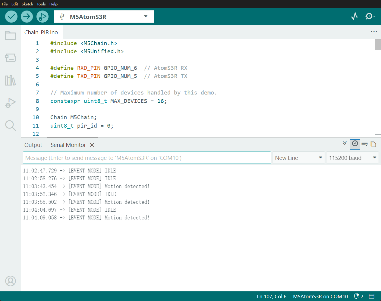
The event trigger mode example runs as follows:
2.2 Polling Mode
In polling mode, the program first disables unsolicited reports and then calls getIRStatus() every 500 ms to query the current PIR status.
#include <M5Chain.h>
#include <M5Unified.h>

#define RXD_PIN GPIO_NUM_6  // AtomS3R RX
#define TXD_PIN GPIO_NUM_5  // AtomS3R TX

// Maximum number of devices handled by this demo.
constexpr uint8_t MAX_DEVICES = 16;

Chain M5Chain;
uint8_t pir_id = 0;
int8_t last_pir_status = -1;

void showStatus(const char *text, uint16_t color)
{
    // Show one centered status message on the AtomS3R display.
    M5.Display.fillScreen(0x0000);
    M5.Display.setTextDatum(middle_center);
    M5.Display.setTextColor(color);
    M5.Display.setTextSize(2);
    M5.Display.drawString(text, 64, 64);
}

void showModeStatus(const char *mode, const char *status, uint16_t color)
{
    // Keep the operating mode visible above the current PIR state.
    M5.Display.fillScreen(0x0000);
    M5.Display.setTextDatum(middle_center);
    M5.Display.setTextColor(color);
    M5.Display.setTextSize(2);
    M5.Display.drawString(mode, 64, 43);
    M5.Display.drawString(status, 64, 78);
}

bool findPIR()
{
    // Enumerate the Chain bus and select the first PIR device.
    uint16_t device_count = 0;
    if (!M5Chain.isDeviceConnected() ||
        M5Chain.getDeviceNum(&device_count) != CHAIN_OK ||
        device_count == 0 || device_count > MAX_DEVICES) {
        return false;
    }

    device_info_t devices[MAX_DEVICES];
    device_list_t device_list{device_count, devices};
    if (!M5Chain.getDeviceList(&device_list)) {
        return false;
    }

    for (uint16_t i = 0; i < device_count; ++i) {
        if (devices[i].device_type == CHAIN_PIR_TYPE_CODE) {
            pir_id = devices[i].id;
            return true;
        }
    }
    return false;
}

void setup()
{
    // Initialize the AtomS3R display and USB serial output.
    auto cfg = M5.config();
    cfg.serial_baudrate = 115200;
    M5.begin(cfg);
    M5.Display.setRotation(3);  // Rotate the display 90 degrees counterclockwise.
    showStatus("STARTING", 0xFFFF);

    M5Chain.begin(&Serial2, 115200, RXD_PIN, TXD_PIN);

    if (!findPIR()) {
        Serial.println("Chain PIR not found");
        showStatus("PIR ERROR", 0xF800);
        return;
    }

    uint8_t operation_status = 0;
    // Disable unsolicited reports so this demo uses polling only.
    chain_status_t status = M5Chain.setPIRDetectTriggerMode(
        pir_id, CHAIN_DETECT_NONE_REPORT_MODE, &operation_status);
    if (status == CHAIN_OK && operation_status == 1) {
        Serial.println("[POLL MODE] IDLE");
        showModeStatus("POLL MODE", "IDLE", 0x07E0);
    } else {
        pir_id = 0;
        Serial.println("Failed to disable event trigger mode");
        showStatus("PIR ERROR", 0xF800);
    }
}

void loop()
{
    if (pir_id == 0) {
        delay(1000);
        return;
    }

    pir_detect_result_t pir_status = CHAIN_PIR_NO_PERSON;
    // Request the current PIR status once every 500 ms.
    chain_status_t status = M5Chain.getIRStatus(pir_id, &pir_status);
    if (status == CHAIN_OK) {
        Serial.println(pir_status == CHAIN_PIR_PERSON
                           ? "[POLL MODE] Motion detected!"
                           : "[POLL MODE] IDLE");
        if (pir_status != last_pir_status) {
            showModeStatus("POLL MODE",
                           pir_status == CHAIN_PIR_PERSON ? "MOTION" : "IDLE",
                           pir_status == CHAIN_PIR_PERSON ? 0xF800 : 0x07E0);
            last_pir_status = pir_status;
        }
    } else {
        Serial.printf("PIR read failed: %d\n", status);
        showStatus("READ ERROR", 0xF800);
    }
    delay(500);
}Polling mode queries and prints the current status every 500 ms. When human motion is detected, the display shows MOTION in red and Serial Monitor outputs [POLL MODE] Motion detected!. When idle, the display shows IDLE in green and Serial Monitor outputs [POLL MODE] IDLE. Change delay(500) to adjust the polling interval.
Compile and upload the polling mode program to the device. Click the button in the upper-right corner of Arduino IDE to open Serial Monitor. The serial output is shown below:
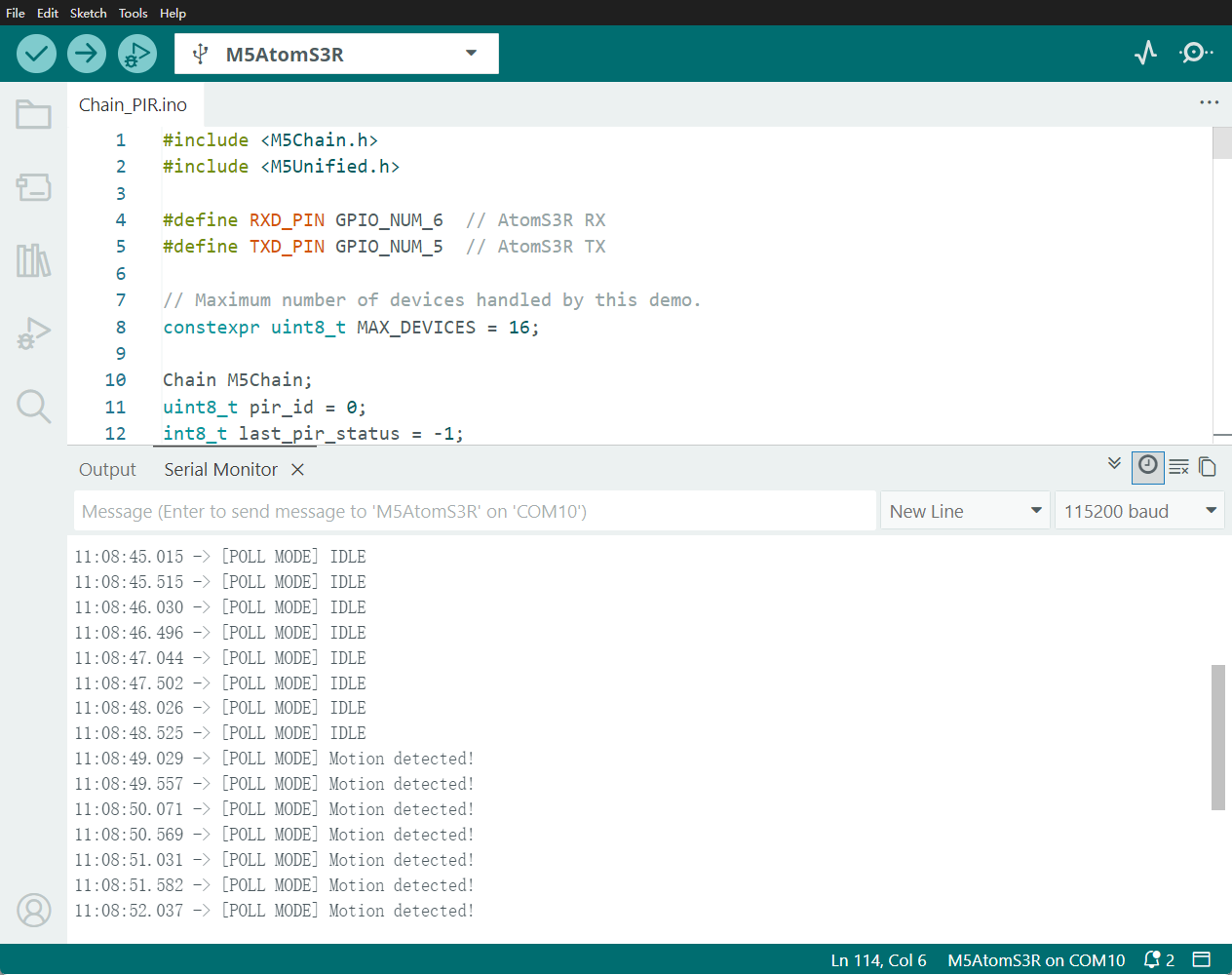
The polling mode example runs as follows:
3.Reference Links
- M5Chain Lib - GitHub
- Chain Series Device Bus Communication
- [Chain PIR Communication Protocol]( Link TBD )