

Arduino Quick Start
2. Devices & Examples
3. M5Unified
4. M5GFX
5. Extensions
Unit
Module
Atomic
Tab5
IoT
Accessories
Unit RS485-ISO Arduino Tutorial
1. Preparation
1. Environment Setup: Refer to the Arduino IDE Getting Started Tutorial to install the IDE, then install the board manager and required driver libraries for the development board you are using.
2. Required Libraries:
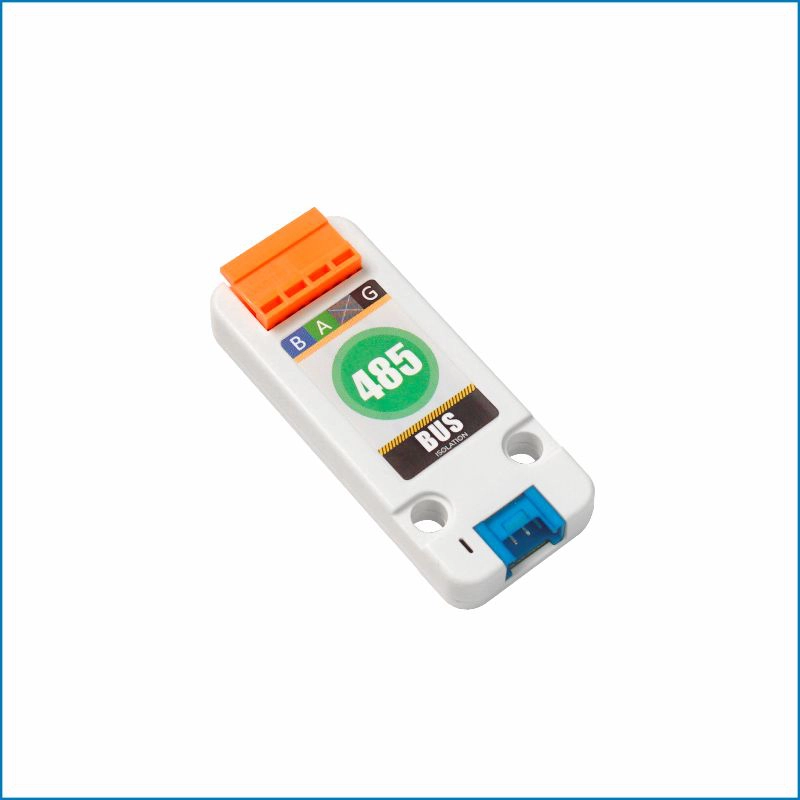
3. Required Hardware:

2. Notes
Pin Compatibility
Since the pin configuration differs between controllers, M5Stack provides an official pin compatibility table for reference. Modify the example program according to the actual pin connections.
3. Example
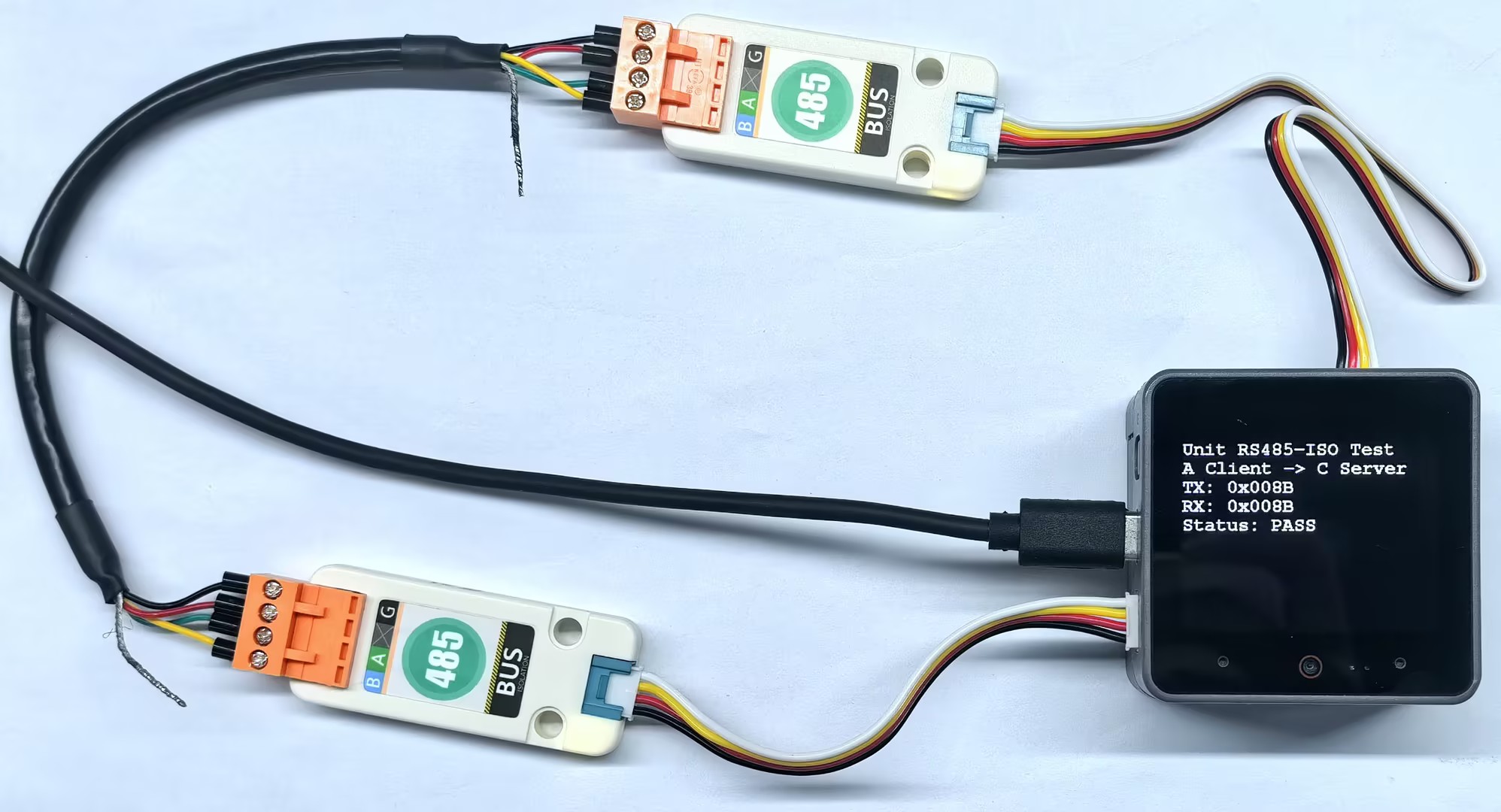
- In this example, one Unit RS485-ISO is connected to each of CoreS3's PORT.A and PORT.C, with the RS485 terminals of the two Units connected A to A and B to B. PORT.A acts as a Modbus RTU Client, while PORT.C acts as a Modbus RTU Server (slave address:
0x01). Every second, the Client writes an incrementing value to the Server's holding register0x0000, then reads the register and compares the result.
CoreS3 PORT.A uses G1 (RX) and G2 (TX), while PORT.C uses G18 (RX) and G17 (TX). Unit RS485-ISO supports automatic transmit/receive direction control internally, so both DE/RE pins are set to -1.
cpp
1 2 3 4 5 6 7 8 9 10 11 12 13 14 15 16 17 18 19 20 21 22 23 24 25 26 27 28 29 30 31 32 33 34 35 36 37 38 39 40 41 42 43 44 45 46 47 48 49 50 51 52 53 54 55 56 57 58 59 60 61 62 63 64 65 66 67 68 69 70 71 72 73 74 75 76 77 78 79 80 81 82 83 84 85 86 87 88 89 90 91 92 93 94 95 96 97 98 99 100 101 102 103 104 105 106 107 108 109 110 111 112 113 114 115 116 117 118 119 120 121 122 123 124
#include "M5Unified.h"
#include <Wire.h>
#include <ArduinoModbus.h>
#include <ArduinoRS485.h>

constexpr uint32_t MODBUS_BAUDRATE = 115200;
constexpr uint8_t SERVER_ID        = 0x01;
constexpr uint16_t REGISTER_ADDR   = 0x0000;

constexpr int PORT_A_RX_PIN = 1;
constexpr int PORT_A_TX_PIN = 2;
constexpr int PORT_C_RX_PIN = 18;
constexpr int PORT_C_TX_PIN = 17;

// PORT.A uses Serial2 as the Modbus RTU Client interface.
RS485Class RS485(Serial2, PORT_A_RX_PIN, PORT_A_TX_PIN, -1, -1);

// PORT.C uses Serial1 as the Modbus RTU Server interface.
RS485Class RS485PortC(Serial1, PORT_C_RX_PIN, PORT_C_TX_PIN, -1, -1);

ModbusRTUClientClass portAClient(RS485);
ModbusRTUServerClass portCServer(RS485PortC);

uint16_t transmitValue = 0;

void modbusServerTask(void *parameter);
void showResult(uint16_t sentValue, long receivedValue);
void haltWithError(const char *message);

void setup()
{
    M5.begin();
    Serial.begin(115200);
    delay(2000);

    M5.Display.setFont(&fonts::FreeMonoBold12pt7b);
    M5.Display.setTextColor(TFT_WHITE, TFT_BLACK);
    M5.Display.clear();
    M5.Display.println("RS485 initializing");

    // Release PORT.A from I2C before using its pins for Serial2.
    Wire.end();

    if (!portCServer.begin(SERVER_ID, MODBUS_BAUDRATE, SERIAL_8N1)) {
        haltWithError("Server init failed");
    }

    if (!portCServer.configureHoldingRegisters(REGISTER_ADDR, 1)) {
        haltWithError("Register init failed");
    }
    portCServer.holdingRegisterWrite(REGISTER_ADDR, 0);

    if (xTaskCreatePinnedToCore(modbusServerTask, "modbus-server", 4096,
                                nullptr, 2, nullptr, 0) != pdPASS) {
        haltWithError("Server task failed");
    }

    if (!portAClient.begin(MODBUS_BAUDRATE, SERIAL_8N1)) {
        haltWithError("Client init failed");
    }
    portAClient.setTimeout(500);

    Serial.println("PORT.A Client and PORT.C Server started");
    delay(100);
}

void loop()
{
    ++transmitValue;

    bool writeSuccess = portAClient.holdingRegisterWrite(
        SERVER_ID, REGISTER_ADDR, transmitValue);

    long receivedValue = -1;
    if (writeSuccess) {
        receivedValue = portAClient.holdingRegisterRead(
            SERVER_ID, REGISTER_ADDR);
    }

    showResult(transmitValue, receivedValue);
    delay(1000);
}

void modbusServerTask(void *parameter)
{
    while (true) {
        portCServer.poll();
        vTaskDelay(1);
    }
}

void showResult(uint16_t sentValue, long receivedValue)
{
    bool success = receivedValue >= 0 &&
                   static_cast<uint16_t>(receivedValue) == sentValue;

    Serial.printf("PORT.A TX: 0x%04X, PORT.C RX/TX: 0x%04lX, %s\n",
                  sentValue, receivedValue, success ? "PASS" : "FAIL");

    M5.Display.clear();
    M5.Display.setCursor(0, 0);
    M5.Display.println("Unit RS485-ISO Test");
    M5.Display.println("A Client -> C Server");
    M5.Display.printf("TX: 0x%04X\n", sentValue);

    if (receivedValue >= 0) {
        M5.Display.printf("RX: 0x%04lX\n", receivedValue);
    } else {
        M5.Display.println("RX: ERROR");
    }
    M5.Display.printf("Status: %s\n", success ? "PASS" : "FAIL");
}

void haltWithError(const char *message)
{
    Serial.println(message);
    M5.Display.clear();
    M5.Display.setCursor(0, 0);
    M5.Display.println(message);

    while (true) {
        delay(1000);
    }
}4. Compile and Upload
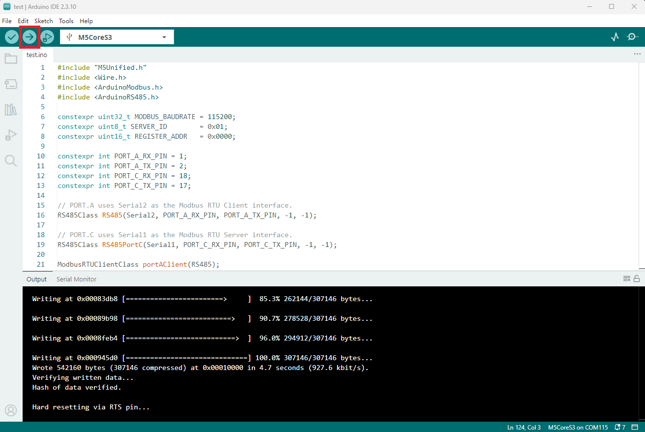
- Copy and paste the example code above into the project code area as needed. Select the device port (refer to Program Compilation and Flashing for details), click the compile and upload button in the upper-left corner of the Arduino IDE, and wait for the program to finish compiling and uploading to the device.
5. RS485 Modbus Communication
- After the device powers on, CoreS3 PORT.A acts as a Modbus RTU Client and sends a holding register write request to PORT.C, which acts as a Modbus RTU Server. After receiving the request, the Server writes the data to the holding register and returns a response. The Client then sends a holding register read request to the Server, and the Server returns the holding register value. The Client compares the value read with the value sent. If they match, PASS is displayed; otherwise, FAIL is displayed.
Page Tools