

Arduino Quick Start
2. Devices & Examples
3. M5Unified
4. M5GFX
5. Extensions
Unit
Atomic
Tab5
IoT
Accessories
Unit Color Arduino Tutorial
1. Preparation
- Environment Setup: Follow the Arduino IDE Getting Started Tutorial to install the IDE, then install the board manager package and required driver libraries for the development board you are using.
- Required Driver Libraries:
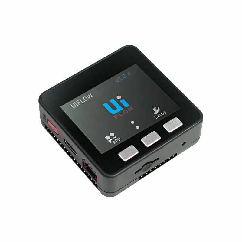
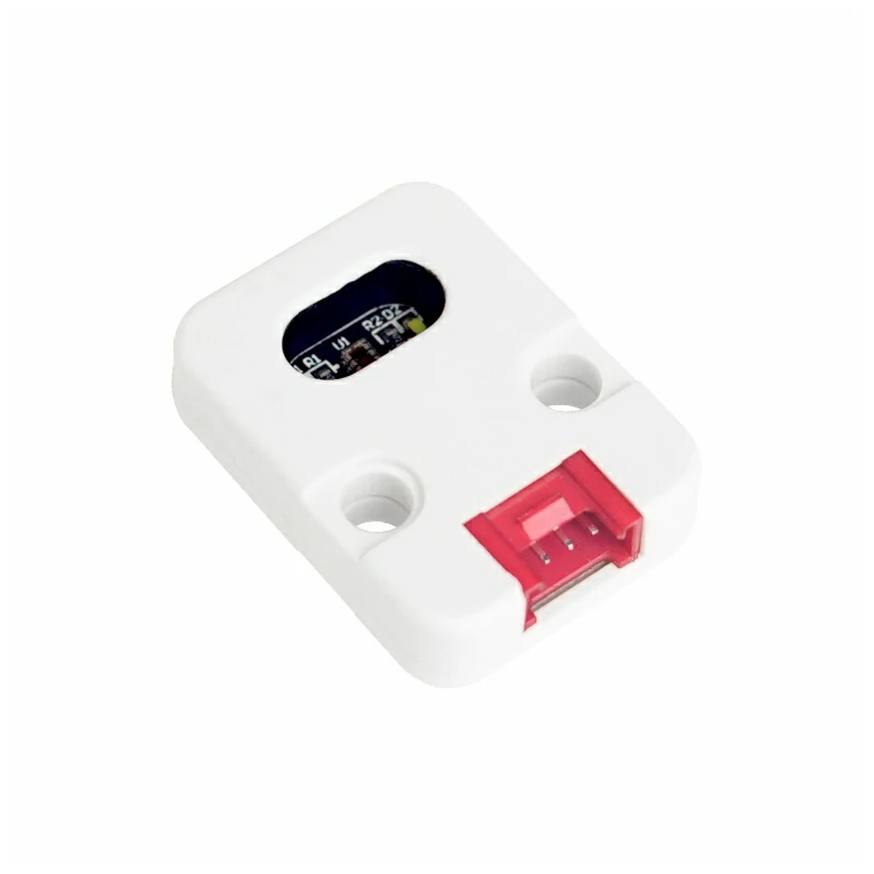
- Required Hardware:
2. Notes
Pin Compatibility
Pin configurations vary between host devices. M5Stack provides an official pin compatibility table for reference. Modify the example program according to the actual pin connections.
3. Example Program
- This tutorial uses Basic V2.7 with Unit Color. Unit Color communicates via I2C at the default address
0x29. Once connected, the corresponding pins areG21 (SDA)andG22 (SCL).
cpp
1 2 3 4 5 6 7 8 9 10 11 12 13 14 15 16 17 18 19 20 21 22 23 24 25 26 27 28 29 30 31 32 33 34 35 36 37 38 39 40 41 42 43 44 45 46 47 48 49 50 51 52 53 54 55 56 57 58 59 60 61 62 63 64 65 66 67 68 69 70 71 72 73
#include <M5Unified.h>
#include <M5GFX.h>
#include "Adafruit_TCS34725.h"

#define commonAnode  true  // set to false if using a common cathode LED.

byte gammatable[256];  // our RGB -> eye-recognized gamma color

static uint16_t color16(uint16_t r, uint16_t g, uint16_t b)
{
    uint16_t _color;
    _color = (uint16_t)(r & 0xF8) << 8;
    _color |= (uint16_t)(g & 0xFC) << 3;
    _color |= (uint16_t)(b & 0xF8) >> 3;
    return _color;
}

Adafruit_TCS34725 tcs = Adafruit_TCS34725(TCS34725_INTEGRATIONTIME_50MS, TCS34725_GAIN_4X);

void setup()
{
    M5.begin();
    M5.Power.begin();
    M5.Lcd.setTextSize(2);
    Serial.println("Color View Test!");
    while (!tcs.begin(TCS34725_ADDRESS, &Wire)) { //PORT.A
        Serial.println("No TCS34725 found ... check your connections");
        M5.Lcd.drawString("No Found sensor.", 50, 100, 4);
        delay(1000);
    }
    tcs.setIntegrationTime(TCS34725_INTEGRATIONTIME_154MS);  // Sets the integration time for the
    tcs.setGain(TCS34725_GAIN_4X);                           // Adjusts the gain on the TCS34725
}

void loop()
{
    uint16_t clear, red, green, blue;
    tcs.getRawData(&red, &green, &blue,
                   &clear);  // Reads the raw red, green, blue and clear channel
                             // values

    // Figure out some basic hex code for visualization.  生成对应的十六进制代码
    uint32_t sum = clear;
    float r, g, b;
    r = red;
    r /= sum;
    g = green;
    g /= sum;
    b = blue;
    b /= sum;
    r *= 256;
    g *= 256;
    b *= 256;
    uint16_t _color = color16((int)r, (int)g, (int)b);

    M5.Lcd.setCursor(0, 20);                 // Place the cursor at (0,20)
    M5.Lcd.fillRect(0, 20, 120, 80, BLACK);  // Fill the screen with a black rectangle

    M5.Lcd.print("C:");
    M5.Lcd.println(clear);
    M5.Lcd.print("R:");
    M5.Lcd.println(red);
    M5.Lcd.print("G:");
    M5.Lcd.println(green);
    M5.Lcd.print("B:");
    M5.Lcd.println(blue);
    M5.Lcd.print("0x");
    M5.Lcd.print((int)r, HEX);
    M5.Lcd.print((int)g, HEX);
    M5.Lcd.print((int)b, HEX);

    delay(1000);
}4. Compile and Upload
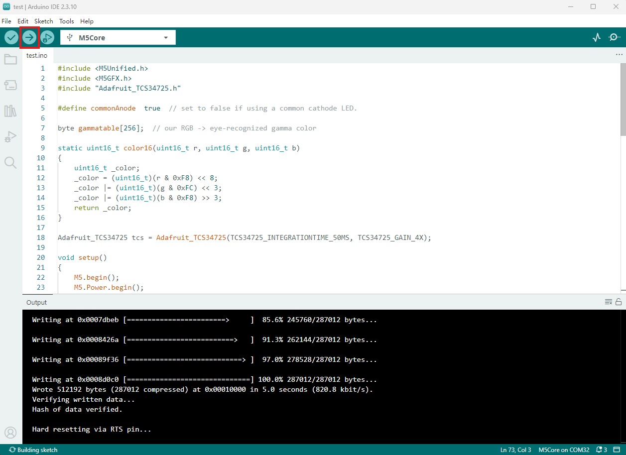
- Copy and paste the example code above into the project code area and select the device port. For details, see Program Compilation and Flashing. Click the compile and upload button in the upper-left corner of Arduino IDE, then wait for the program to compile and upload to the device.
5. Color Recognition
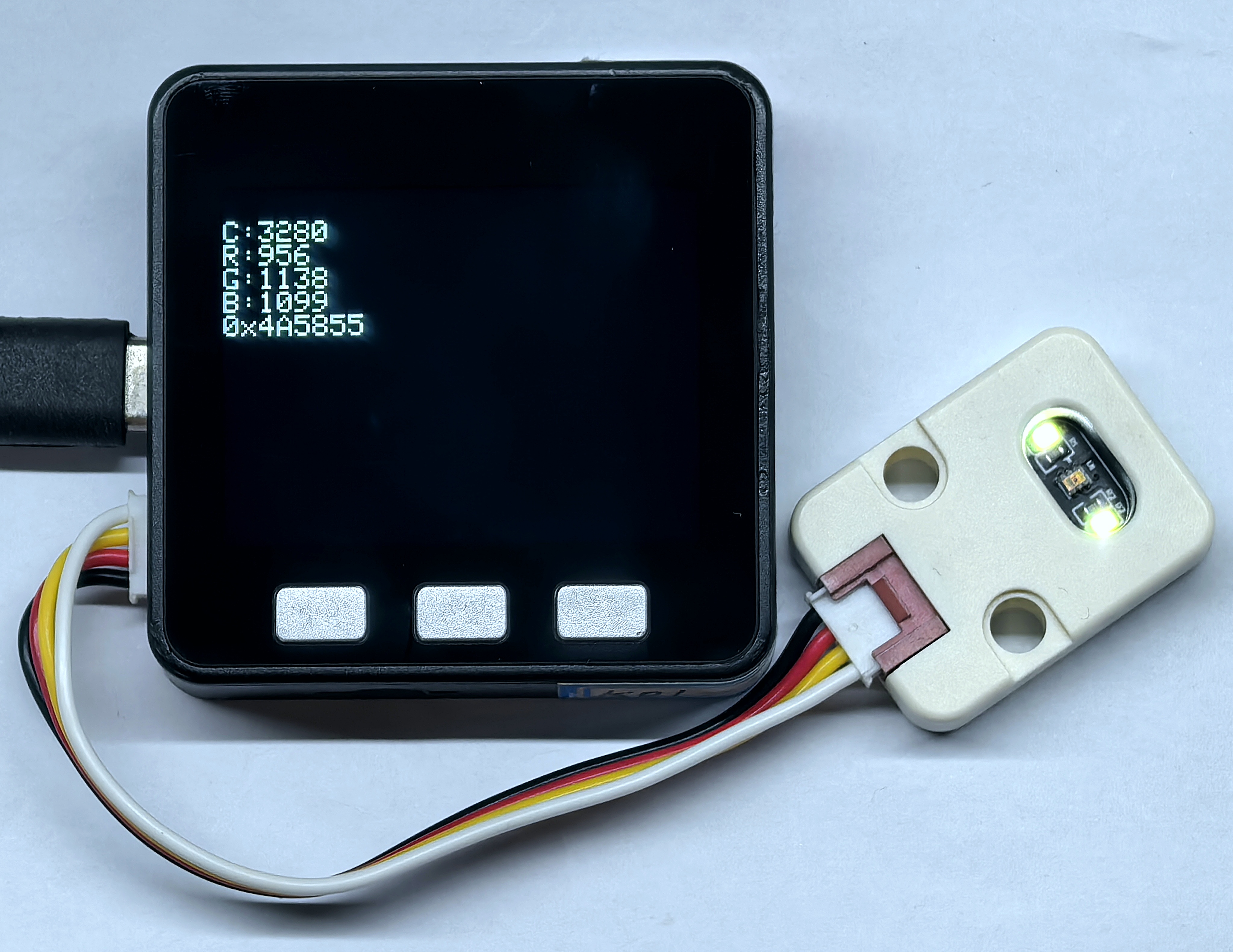
- After the program starts, the screen refreshes once per second to show the raw clear, red, green, and blue channel values collected by Unit Color, together with the converted RGB hexadecimal data.
Page Tools