

Arduino Quick Start
2. Devices & Examples
3. M5Unified
4. M5GFX
5. Extensions
Unit
Atomic
Tab5
IoT
Accessories
Unit Light Arduino Tutorial
1. Preparation
- Environment Setup: Follow the Arduino IDE Getting Started Tutorial to install the IDE, then install the board manager package and required driver libraries for the development board you are using.
- Required Driver Libraries:
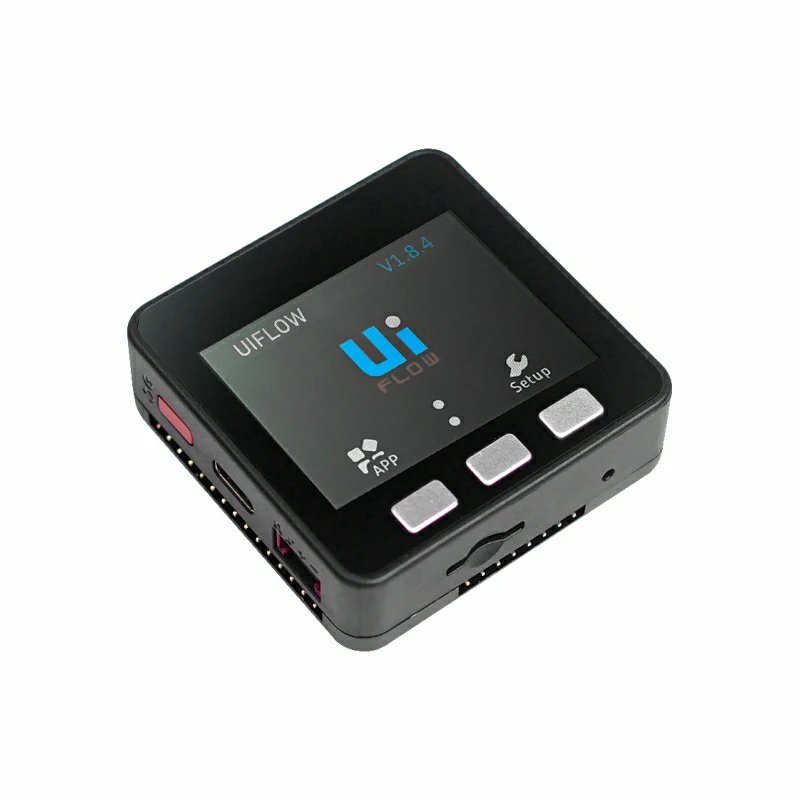
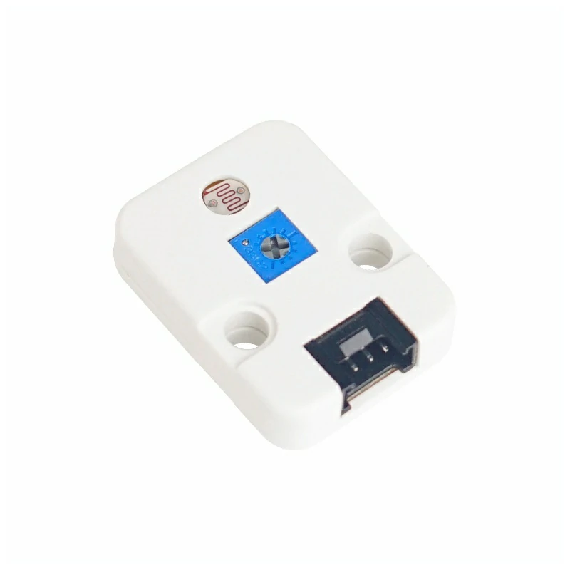
- Required Hardware:
2. Notes
Pin Compatibility
Pin configurations vary between host devices. M5Stack provides an official pin compatibility table for reference. Modify the example program according to the actual pin connections.
3. Example Program
- This tutorial uses Basic V2.7 with Unit Light. Unit Light provides both analog and digital outputs. Adjust the
A_PINandD_PINdefinitions in the program according to the actual circuit connections. The program below usesG36(A_PIN)andG26(D_PIN).
Note
The digital output threshold of Unit Light can be adjusted using the potentiometer on the module, while the analog output changes with ambient light intensity.
cpp
1 2 3 4 5 6 7 8 9 10 11 12 13 14 15 16 17 18 19 20 21 22 23 24 25 26 27 28 29 30 31 32 33 34
#include <M5Unified.h>
#include <M5GFX.h>

#define A_PIN 36
#define D_PIN 26

M5Canvas img(&M5.Lcd);

void setup()
{
    M5.begin();
    M5.Power.begin();
    img.setColorDepth(8);
    img.createSprite(320, 240);
    img.setTextSize(2);
    // Set pin as input mode
    pinMode(A_PIN, INPUT);
    pinMode(D_PIN, INPUT);
}

void loop()
{
    static uint16_t digitalRead_value = 0, analogRead_value = 0;
    analogRead_value = analogRead(A_PIN);
    digitalRead_value = digitalRead(D_PIN);
    img.fillRect(0, 0, 320, 240, 0x00);
    img.drawCenterString("Unit Light Test", 160, 5);
    img.setCursor(90, 30);
    img.printf("Analog:%d\n", analogRead_value);
    img.setCursor(90, 50);
    img.printf("Digital:%d\n", digitalRead_value);
    img.pushSprite(0, 0);
    delay(10);
}4. Compile and Upload
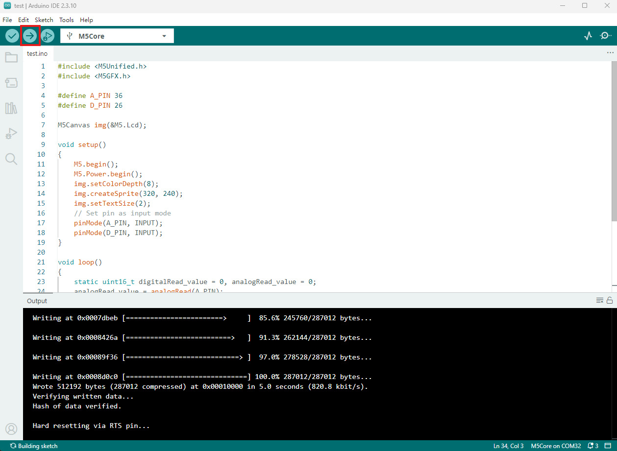
- Copy and paste the example code above into the project code area and select the device port. For details, see Program Compilation and Flashing. Click the compile and upload button in the upper-left corner of Arduino IDE, then wait for the program to compile and upload to the device.
5. Light Detection
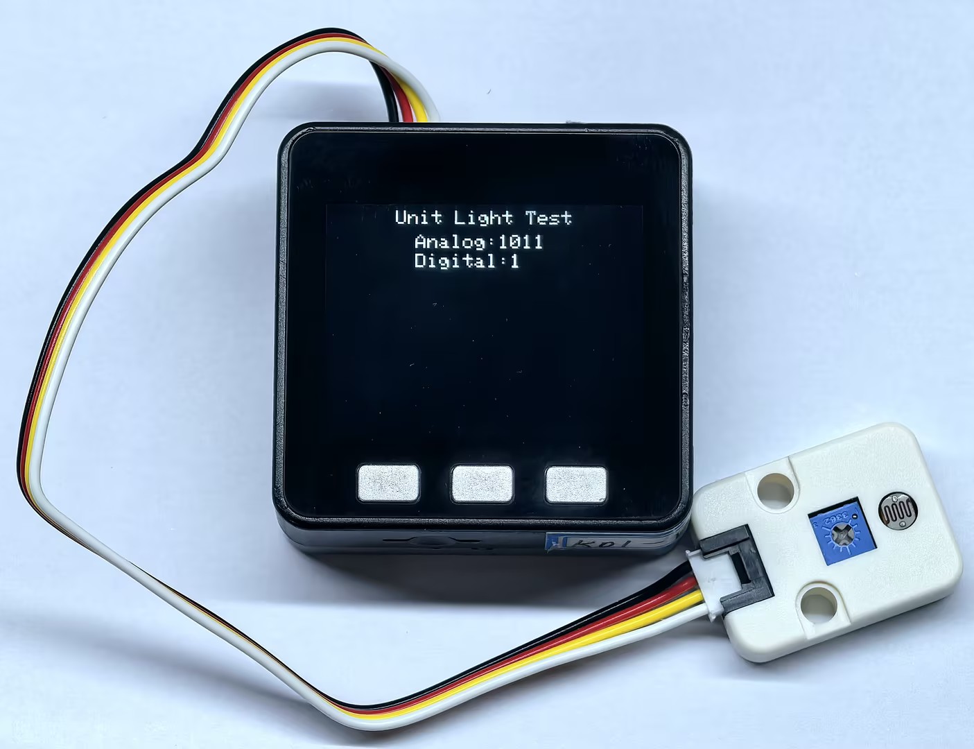
- After the program starts, the screen continuously displays the analog and digital readings from Unit Light. Change the light intensity on the sensor surface and adjust the potentiometer on the module to observe changes in the
Analogvalue and switching of theDigitalstate.
Page Tools