Arduino Quick Start
2. Devices & Examples
3. M5Unified
4. M5GFX
5. Extensions & Examples
Unit
Base
Base LAN v1.2 Arduino Tutorial
1. Preparations
- Environment Setup: Refer to the Arduino IDE Getting Started Guide to complete IDE installation, and install the corresponding board manager and required driver libraries based on the development board being used.
- Required Driver Libraries:
Note
You need to download the latest library version from GitHub: M5-Ethernet - M5Stack GitHub. Do not download from Arduino Library. (For any questions, please refer to this tutorial)
- Required Hardware Products:

2. Notes
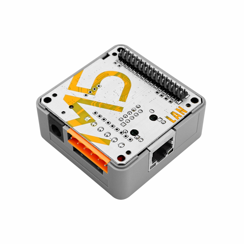
Communication Expansion Board
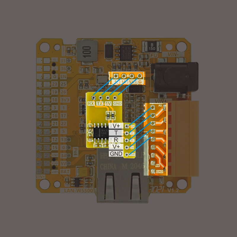
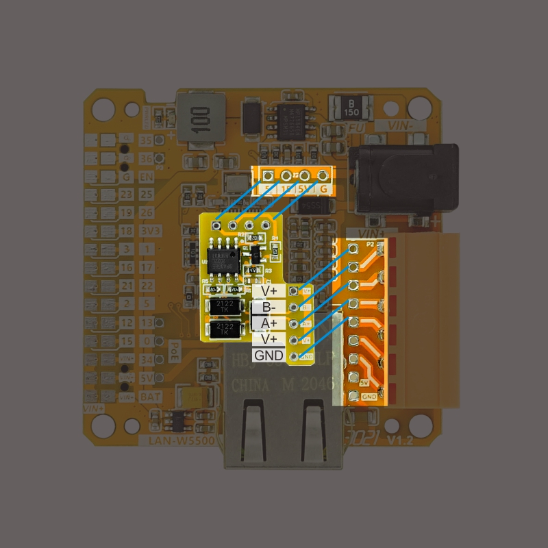
The LAN BASE V12 comes standard with TTL-RS485 + TTL-RS232 adapter boards for different communication interfaces. Soldering positions are shown below. For actual GPIO connections, please refer to the pin mapping table.
- RS232 Adapter Board Soldering Position or RS485 Adapter Board Soldering Position
Pin Compatibility
Since each host device has different pin configurations, please refer to the Pin Compatibility Table in the product documentation before use, and modify the example program according to the actual pin connections.
3. Example Program
- The main controller device used in this tutorial is CoreS3 with Base LAN v1.2. This Ethernet controller base has multiple communication interfaces. Modify the pin definitions in the program according to the actual circuit connections.
3.1 Serial Data Reception
cpp
1 2 3 4 5 6 7 8 9 10 11 12 13 14 15 16 17 18 19 20 21 22 23 24 25 26 27 28 29 30 31 32 33 34 35 36
#include <M5Unified.h>
void setup()
{
M5.begin();
M5.Display.fillScreen(WHITE);
M5.Display.setTextFont(&fonts::FreeMono12pt7b);
M5.Display.setTextColor(BLACK);
M5.Display.setCursor(0, 0);
Serial.begin(115200);
Serial2.begin(115200, SERIAL_8N1, 1, 13);
}
void loop()
{
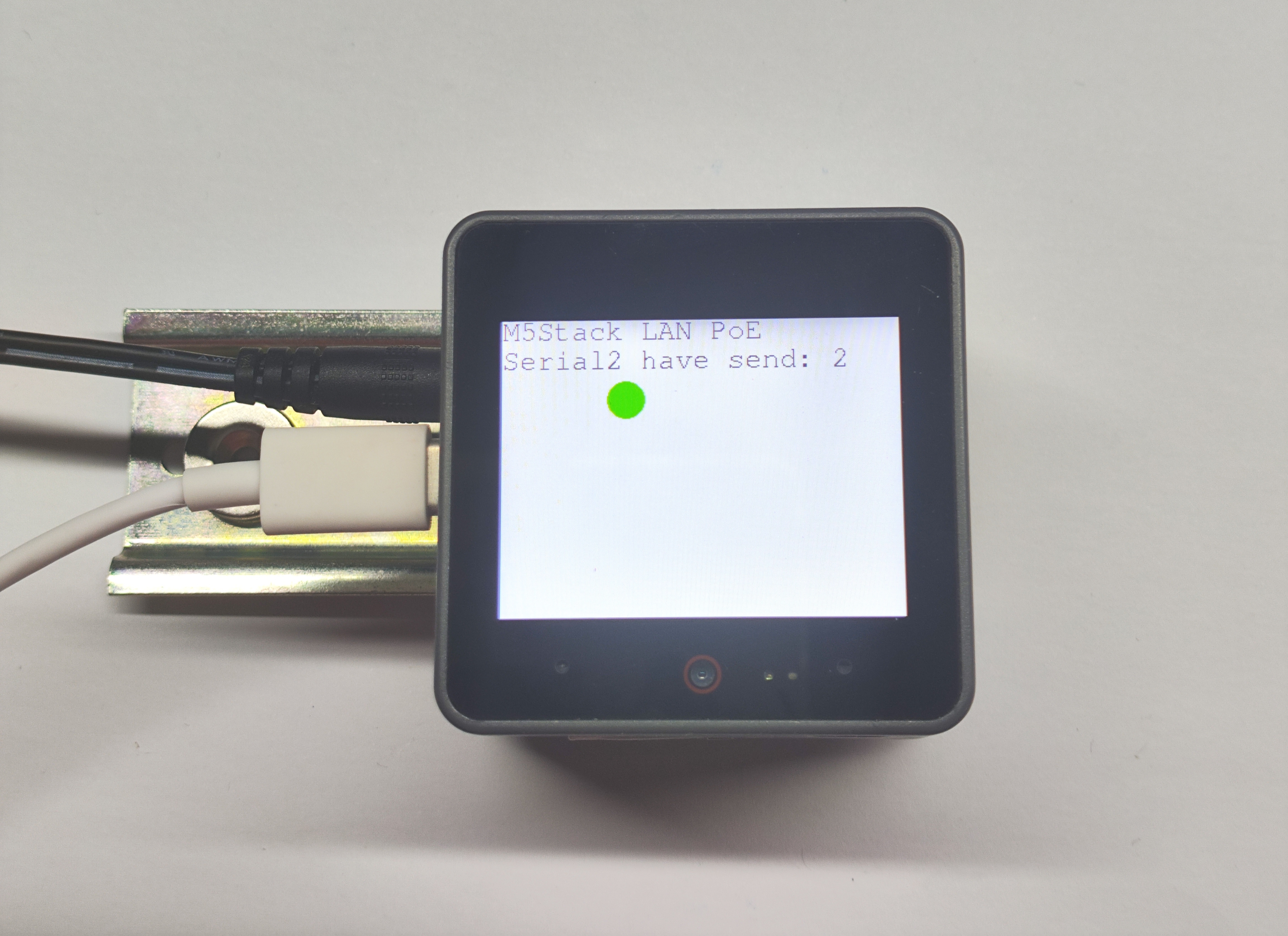
M5.Display.setCursor(0, 0);
M5.Display.printf("M5Stack LAN PoE\n");
if (Serial.available()) { // If the serial port receives a
// message. 如果串口收到信息
int ch = Serial.read(); // Read the message. 读取信息
Serial2.write(ch);
M5.Display.fillCircle(100, 65, 15, GREEN); // Set the light to Green. 设置灯为绿色
}
else M5.Display.fillCircle(100, 65, 15, WHITE);
Serial2.write('a');
delay(50);
if (Serial2.available()) { // If the serial port receives a
// message. 如果串口收到信息
int ch = Serial2.read(); // Read the message. 读取信息
Serial.write(ch);
M5.Display.fillCircle(100, 65, 15, GREEN);
delay(50);
} else M5.Display.fillCircle(100, 65, 15, WHITE);
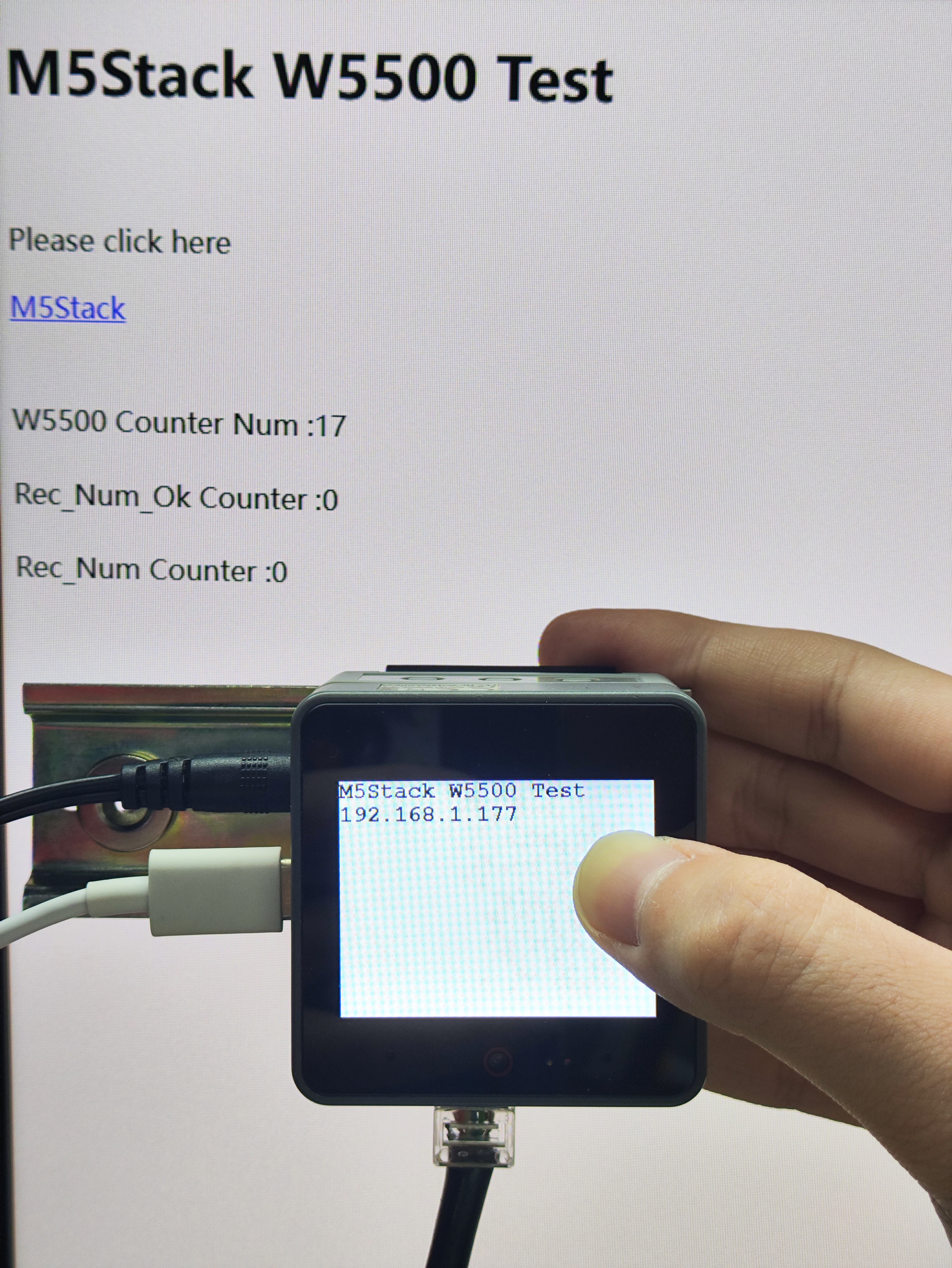
}3.2 WebServer Usage
- In this demo, the PC and M5Stack communicate via Ethernet for data transmission.
cpp
1 2 3 4 5 6 7 8 9 10 11 12 13 14 15 16 17 18 19 20 21 22 23 24 25 26 27 28 29 30 31 32 33 34 35 36 37 38 39 40 41 42 43 44 45 46 47 48 49 50 51 52 53 54 55 56 57 58 59 60 61 62 63 64 65 66 67 68 69 70 71 72 73 74 75 76 77 78 79 80 81 82 83 84 85 86 87 88 89 90 91 92 93 94 95 96 97 98 99 100 101 102 103 104 105 106 107 108 109 110 111 112 113 114 115 116 117 118 119 120 121 122 123 124 125
#include <M5Unified.h>
#include <SPI.h>
#include <M5_Ethernet.h>

#define SCK  36
#define MISO 35
#define MOSI 37
#define CS   9

//  01 05 00 01 02 00 9d 6a
char uart_buffer[8]    = {0x01, 0x05, 0x00, 0x01, 0x02, 0x00, 0x9d, 0x6a};
char uart_rx_buffer[8] = {0};

char Num                   = 0;
char stringnum             = 0;
unsigned long W5500DataNum = 0;
unsigned long Send_Num_Ok  = 0;
unsigned long Rec_Num      = 0;
unsigned long Rec_Num_Ok   = 0;

// Enter a MAC address and IP address for your controller below.
// The IP address will be dependent on your local network:
byte mac[] = {0xDE, 0xAD, 0xBE, 0xEF, 0xFE, 0xED};
IPAddress ip(192, 168, 1, 177);

// Initialize the Ethernet server library
// with the IP address and port you want to use
// (port 80 is default for HTTP):
EthernetServer server(80);

void setup()
{
    // Open serial communications and wait for port to open:
    M5.begin();
    Serial.begin(115200);
    SPI.begin(SCK, MISO, MOSI, -1);
    Ethernet.init(CS);
    // start the Ethernet connection and the server:
    Ethernet.begin(mac, ip);
    server.begin();
    Serial.print("server is at ");
    Serial.println(Ethernet.localIP());

    M5.Display.fillScreen(WHITE);
    M5.Display.setTextFont(&fonts::FreeMonoBold12pt7b);
    M5.Display.setTextColor(BLACK);
    M5.Display.setCursor(0, 0);
    M5.Display.println("M5Stack W5500 Test");
    M5.Display.print(Ethernet.localIP());
}

void loop()
{
    // listen for incoming clients
    EthernetClient client = server.available();
    if (client) {
        Serial.println("new client");
        // an http request ends with a blank line
        boolean currentLineIsBlank = true;
        while (client.connected()) {
            if (client.available()) {
                char c = client.read();
                Serial.write(c);
                // if you've gotten to the end of the line (received a newline
                // character) and the line is blank, the http request has ended,
                // so you can send a reply
                if (c == '\n' && currentLineIsBlank) {
                    // send a standard http response header
                    client.println("HTTP/1.1 200 OK");
                    client.println("Content-Type: text/html");
                    client.println("Connection: close");  // the connection will be closed
                                                          // after completion of the
                                                          // response
                    client.println("Refresh: 5");         // refresh the page
                                                          // automatically every 5 sec
                    client.println();
                    client.println("<!DOCTYPE HTML>");
                    client.println("<html>");

                    client.println("<body>");
                    client.println("<h1>M5Stack W5500 Test</h1>");
                    client.println("<br />");
                    client.println("<p>Please click here</p>");
                    client.println("<a href=\"http://www.M5Stack.com\">M5Stack</a>");
                    client.println("<br />");
                    client.println("<br />");
                    client.println("<br />");

                    client.print("W5500 Counter Num :");
                    client.print(W5500DataNum);
                    client.println("<br />");
                    client.println("<br />");
                    W5500DataNum++;

                    client.print("Rec_Num_Ok Counter :");
                    client.print(Rec_Num_Ok);
                    client.println("<br />");
                    client.println("<br />");

                    client.print("Rec_Num Counter :");
                    client.print(Rec_Num);
                    client.println("<br />");
                    client.println("<br />");

                    client.println("</body>");

                    client.println("</html>");
                    break;
                }
                if (c == '\n') {
                    // you're starting a new line
                    currentLineIsBlank = true;
                } else if (c != '\r') {
                    // you've gotten a character on the current line
                    currentLineIsBlank = false;
                }
            }
        }
        // give the web browser time to receive the data
        delay(1);
        // close the connection:
        client.stop();
        Serial.println("client disconnected");
    }
}4. Compile and Upload
Download Mode: Different devices require entering download mode before programming. This process may vary depending on the main controller. For details, please refer to the device programming tutorial list at the bottom of the Arduino IDE Getting Started Guide page.
For CoreS3: Press and hold the reset button (about 2 seconds) until the internal green LED lights up, then release. The device will enter download mode and wait for programming.
.gif)
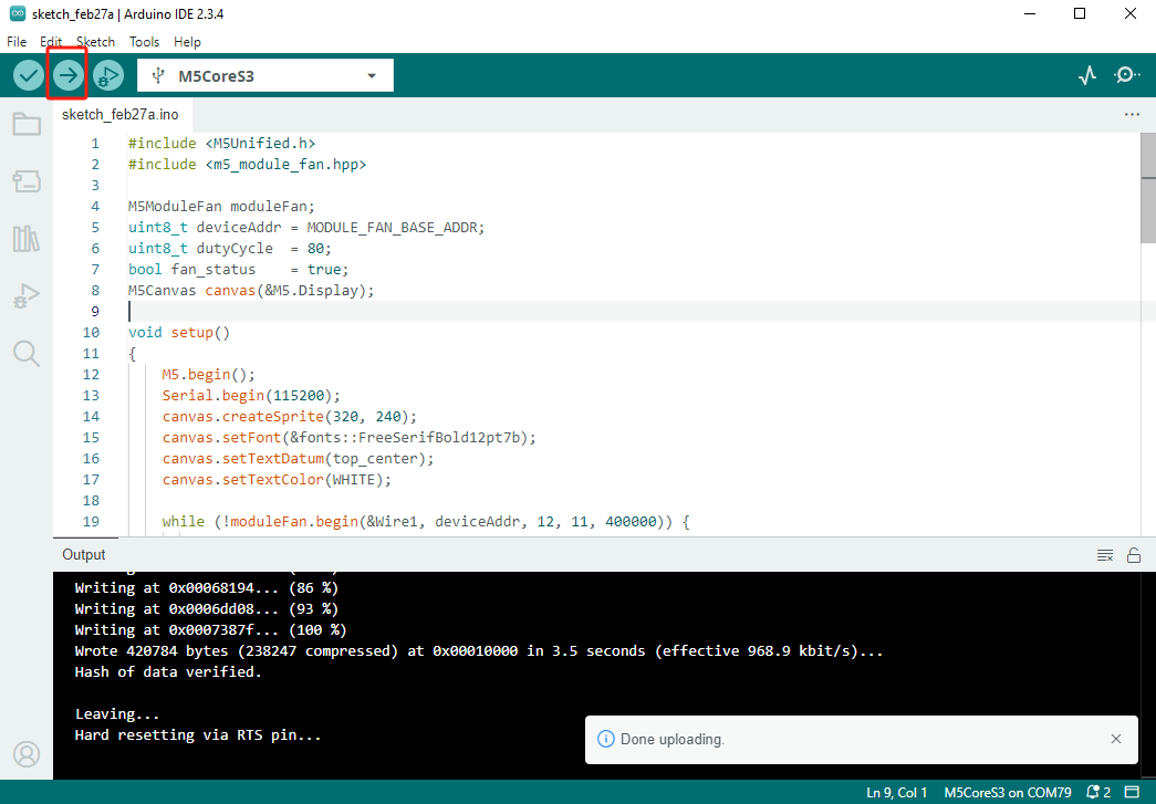
- Select the device port and click the compile/upload button in the top-left corner of Arduino IDE. Wait for the program to complete compilation and upload to the device.
5. Communication Results
- Serial Communication Test: This module supports both RS485 and RS232 communication methods, both using Serial2 in the software.
- WebServer Test:
- Connect PC directly to Base LAN PoE v1.2 module using Ethernet cable.
- On module side (in firmware), configure static IP as
192.168.1.177with subnet mask255.255.255.0. - On PC side, manually set wired network card IP to
192.168.1.x(wherexis 2~254 and ≠177), subnet mask255.255.255.0, default gateway can be left blank. - Verify both devices are on same network segment by testing connectivity with
ping 192.168.1.177. - Enter
http://192.168.1.177in PC browser to access the built-in web server.