Arduino Quick Start
2. Devices & Examples
3. M5Unified
4. M5GFX
5. Extensions
Unit
Atomic
Tab5
IoT
Accessories
Unit RF433 Arduino Tutorial
1. Preparations
Environment Setup: Refer to the Arduino IDE Getting Started Guide to complete IDE installation, and install the corresponding board manager and required driver libraries based on the development board being used.
Required Driver Libraries:
Note
You need to download the latest library version from GitHub: RF433any - GitHub. Do not download from Arduino Library. (For any questions, please refer to this tutorial)
- Required Hardware Products:

2. Notes
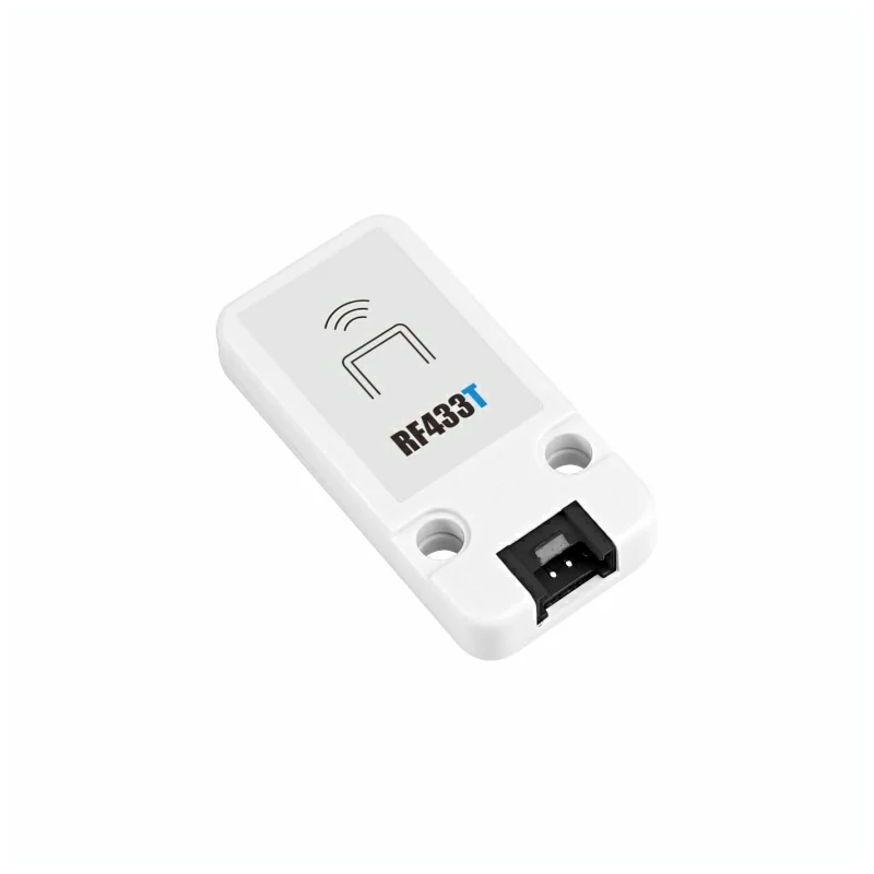
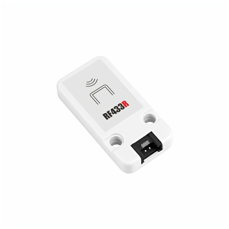
Transceiver Pair
This RF433 set is designed for paired use, requiring one Unit RF433T as the transmitter module and one Unit RF433R as the receiver module.
Pin Compatibility
Since each host device has different pin configurations, please refer to the RF433T Pin Compatibility Table and RF433R Pin Compatibility Table in the product documentation before use, and modify the example program according to the actual pin connections.
3. Example Program
- In this tutorial, Basic v2.7 with Unit RF433T is used as the transmitter, and CoreS3 with Unit RF433R is used as the receiver. The modules have two circuit connection types: DOUT and DIN. Please modify the pin definitions in the program according to the actual circuit connections.
3.1 RF433T Transmitter
cpp
1 2 3 4 5 6 7 8 9 10 11 12 13 14 15 16 17 18 19 20 21 22 23 24 25 26 27 28 29 30 31 32 33 34 35 36 37 38 39 40 41 42 43 44 45 46 47 48 49 50 51 52 53 54 55 56 57 58 59 60 61 62 63 64 65 66 67 68 69 70 71 72 73 74 75 76 77 78 79 80
#include <M5Unified.h>

#define TX_PIN 21

uint8_t data[5] = {0xAA, 0x55, 0x01, 0x02, 0x03};

void pulse(int high, int low) {
    digitalWrite(TX_PIN, HIGH);
    delayMicroseconds(high);
    digitalWrite(TX_PIN, LOW);
    delayMicroseconds(low);
}

void sendCorrected() {
    noInterrupts();

    digitalWrite(TX_PIN, LOW);
    delayMicroseconds(10000);

    pulse(5000, 2500);
    pulse(2500, 1250);

    pulse(8000, 4000);

    for (int byte = 0; byte < 5; byte++) {
        for (int bit = 7; bit >= 0; bit--) {
            if (data[byte] & (1 << bit)) {
                pulse(600, 300);
            } else {
                pulse(300, 600);
            }
        }
    }

    pulse(8000, 10000);

    interrupts();
}

void setup() {
    M5.begin();
    Serial.begin(115200);

    pinMode(TX_PIN, OUTPUT);
    digitalWrite(TX_PIN, LOW);

    M5.Display.fillRect(0, 0, 320, 240, WHITE);
    M5.Display.setTextColor(BLACK);
    M5.Display.setFont(&fonts::FreeMonoBold12pt7b);
    M5.Display.setCursor(0, 0);
    M5.Display.println("Corrected RF433T");
    M5.Display.println("Click Btn A to send");

    Serial.println("Corrected RF433 Transmitter Ready");
}

void loop() {
    M5.update();

    if (M5.BtnA.wasPressed()) {
        Serial.println("SEND CORRECTED");

        sendCorrected();
        delay(100);

        Serial.print("Sent: ");
        for (int i = 0; i < 5; i++) {
            Serial.printf("%02X ", data[i]);
        }
        Serial.println();

        M5.Display.print("Sent: ");
        for (int i = 0; i < 5; i++) {
            M5.Display.printf("%02X ", data[i]);
        }
        M5.Display.println("");
    }

    delay(10);
}3.2 RF433R Receiver
cpp
1 2 3 4 5 6 7 8 9 10 11 12 13 14 15 16 17 18 19 20 21 22 23 24 25 26 27 28 29 30 31 32 33 34 35 36 37 38 39 40 41 42 43 44 45 46 47 48 49 50 51 52 53 54 55 56 57 58
#include "RF433any.h"
#include <M5Unified.h>

#define PIN_RFINPUT  1

void setup() {
    M5.begin();
    M5.Display.fillRect(0, 0, 320, 240, WHITE);
    M5.Display.setTextColor(BLACK);
    M5.Display.setFont(&fonts::FreeMonoBold12pt7b);
    M5.Display.setCursor(0, 0);
    M5.Display.println("RF433 Receiver");
    pinMode(PIN_RFINPUT, INPUT);
    Serial.begin(115200);
    Serial.println("Waiting for signal\n");
    M5.Display.println("Waiting for signal");
}

Track track(PIN_RFINPUT);

void loop() {
    track.treset();

    while (!track.do_events())
        delay(1);

    Decoder *pdec0 = track.get_data(
        RF433ANY_FD_DECODED | RF433ANY_FD_DEDUP | RF433ANY_FD_NO_ERROR
    );
    for (Decoder *pdec = pdec0; pdec != nullptr; pdec = pdec->get_next()) {
        Serial.print("Received ");
        M5.Display.println("Received \r\n");
        Serial.print(pdec->get_nb_bits());
        M5.Display.print(pdec->get_nb_bits());
        Serial.print(" bits (x");
        M5.Display.println(" bits (x");
        Serial.print(pdec->get_repeats() + 1);
        M5.Display.print(pdec->get_repeats() + 1);
        Serial.print("): ");
        M5.Display.println(": ");
        char *buf = pdec->get_pdata()->to_str();
            // DEFENSIVE PROGRAMMING
            //   The option RF433ANY_FD_DECODED above guarantees there's always
            //   something decoded. Test done though, just in case.
        if (buf) {
            Serial.println(buf);
            M5.Display.println(buf);
            free(buf);
        }
    }
    delete pdec0;
    delay(2000);
    M5.Display.fillRect(0, 40, 320, 220, WHITE);
    M5.Display.setCursor(0, 40);
}

// vim: ts=4:sw=4:tw=80:et
4. Compile and Upload
Download Mode: Different devices require entering download mode before program burning. This process may vary depending on the main controller device. For details, please refer to the device programming tutorial list at the bottom of the Arduino IDE Getting Started Guide page for specific operations.
For CoreS3: Press and hold the reset button (about 2 seconds) until the internal green LED lights up, then release. The device will now enter download mode and wait for programming.
.gif)
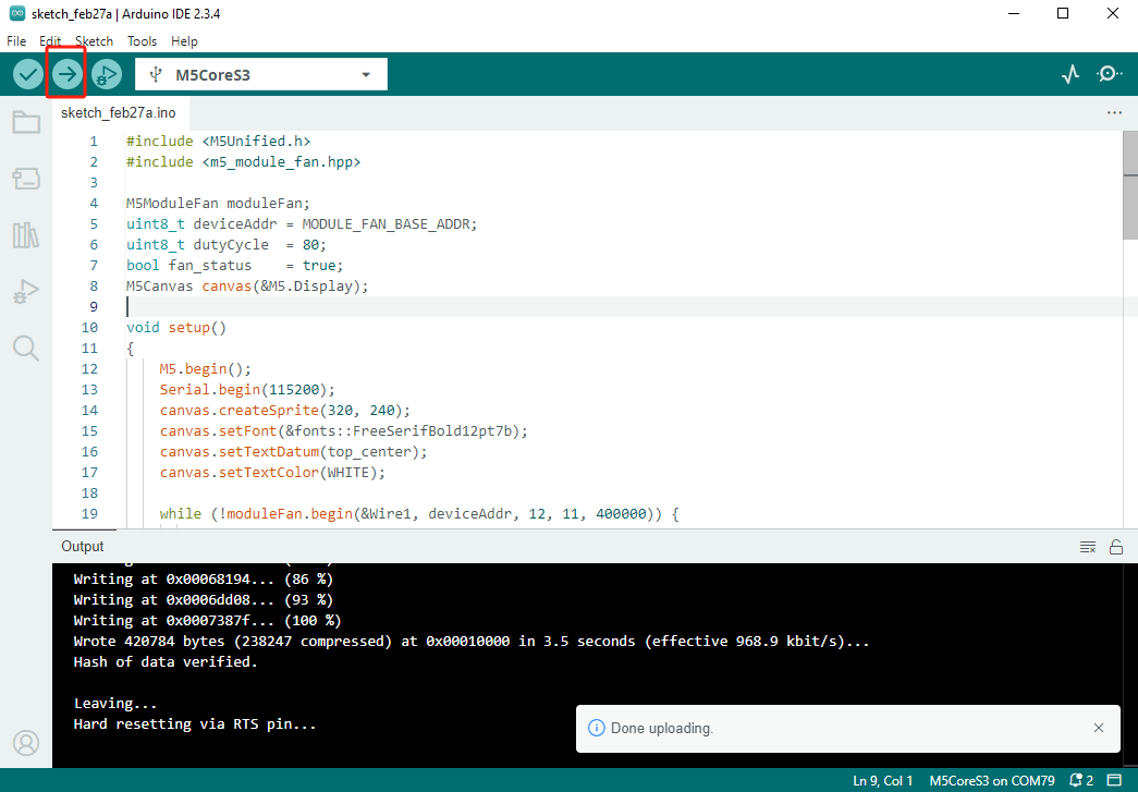
- Select the device port and click the compile/upload button in the top-left corner of Arduino IDE. Wait for the program to complete compilation and upload to the device.
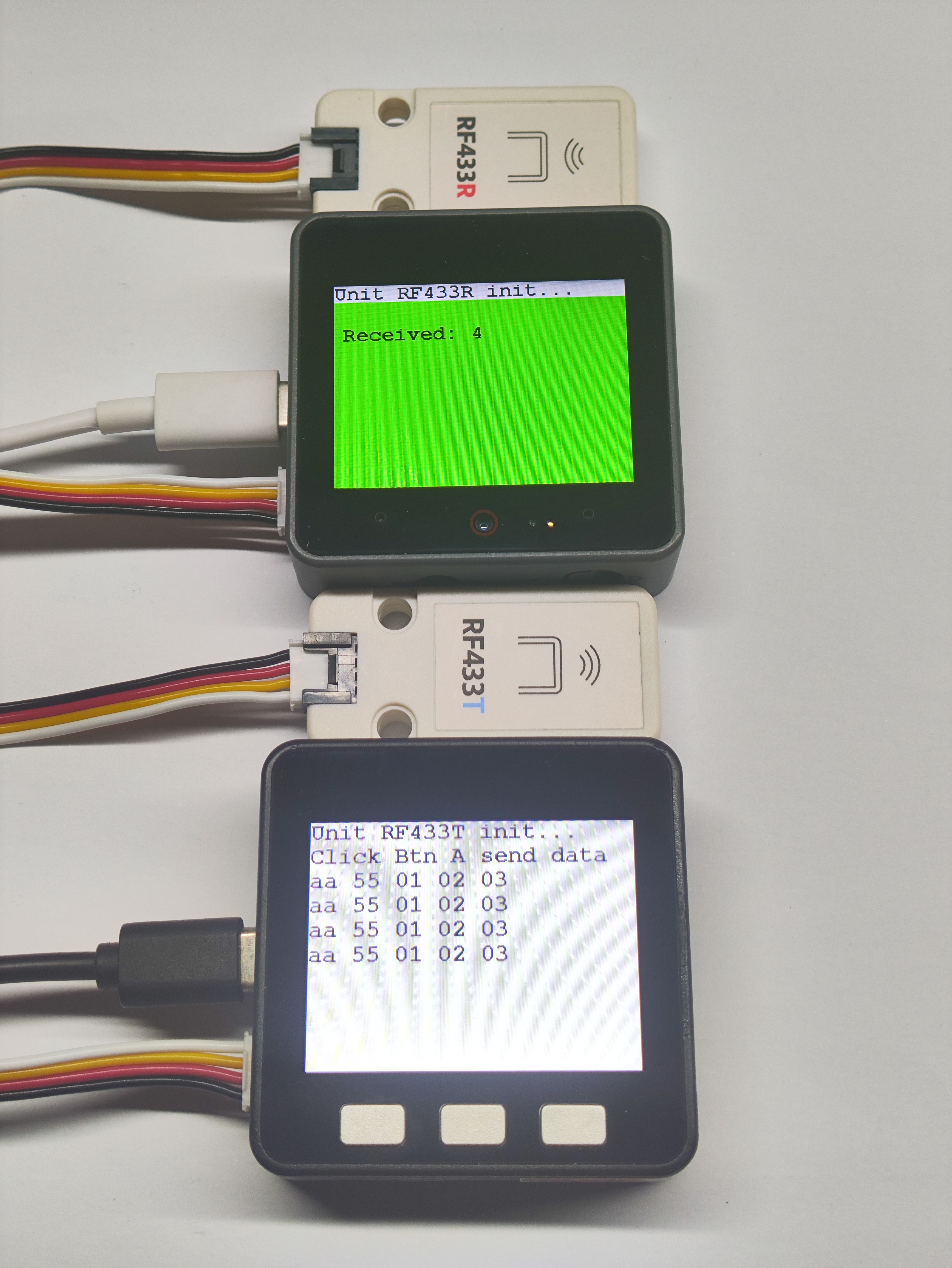
5. Communication Test
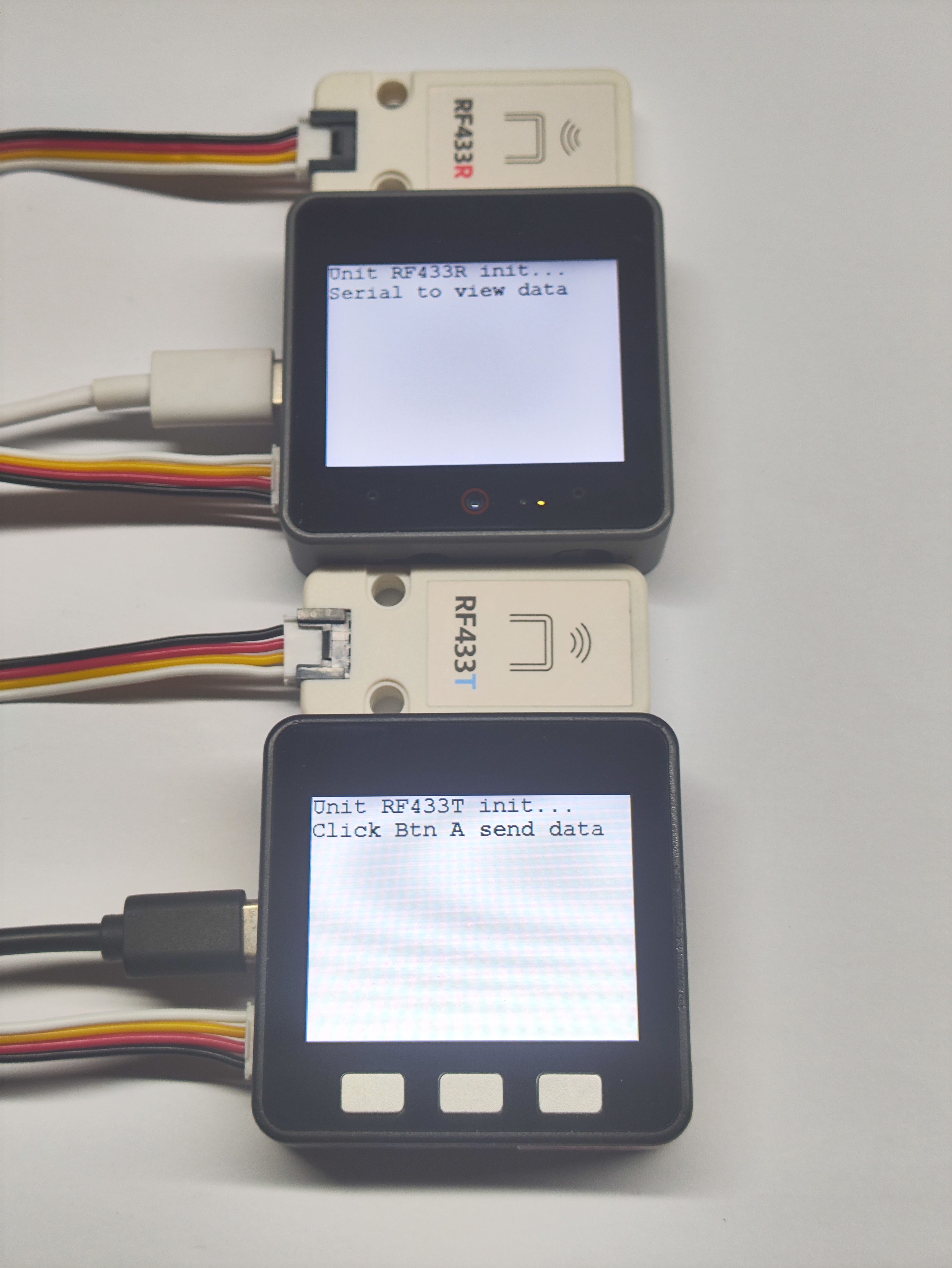
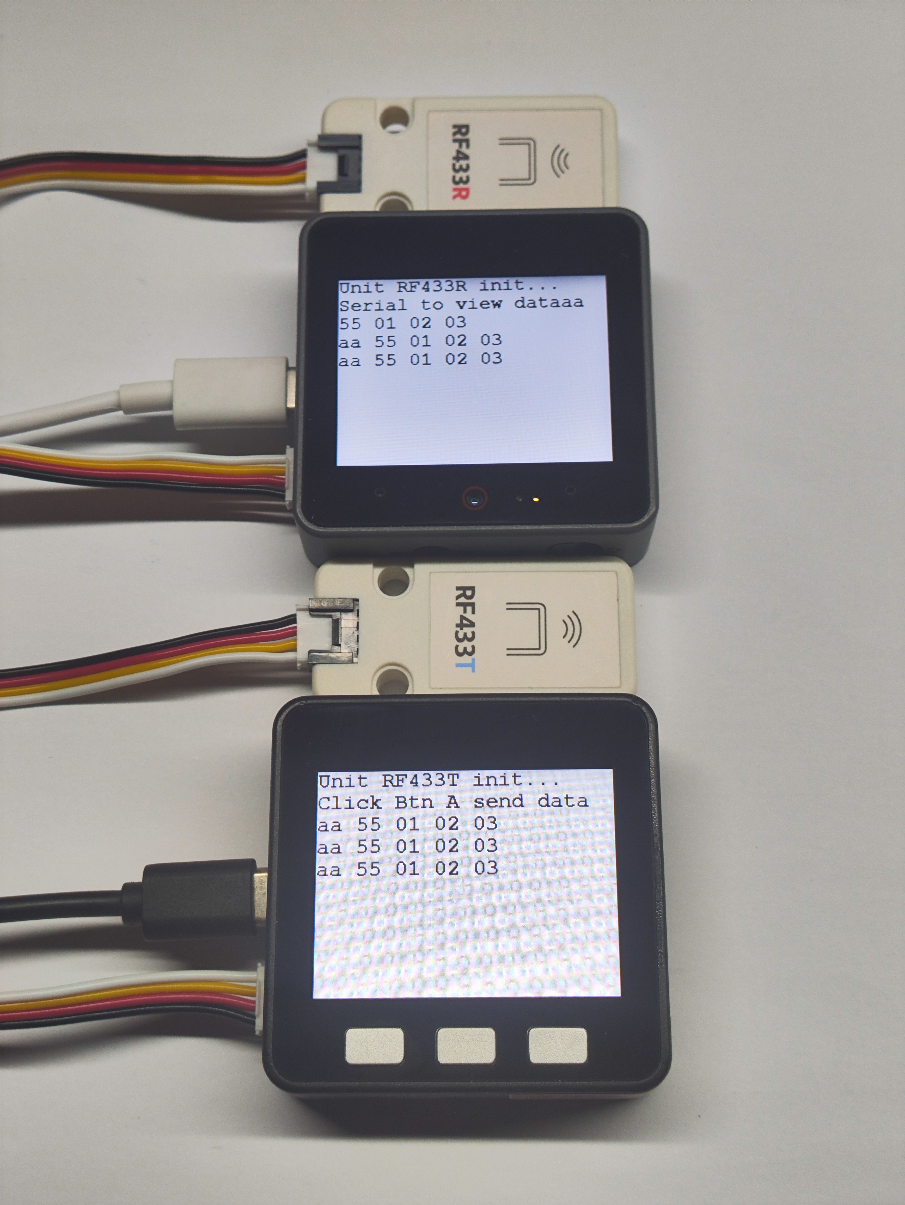
- When Button A on Basic v2.7 is pressed, it will send a data packet via RF433T. If CoreS3 successfully receives the packet through RF433R, it will print the data via serial port and display it on the screen in real-time.
- When four successful communications occur between the two devices, the CoreS3 screen will turn green to indicate success.