

Arduino Quick Start
2. Devices & Examples
3. M5Unified
4. M5GFX
5. Extensions
Unit
Atomic
Tab5
IoT
Accessories
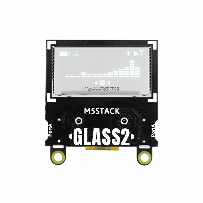
Unit Glass2 Arduino Tutorial
1.Preparation
- Environment setup: Refer to the Getting Started with Arduino IDE to complete the IDE installation. Install the corresponding board package and required driver libraries according to the development board you are using.
- Required driver libraries:
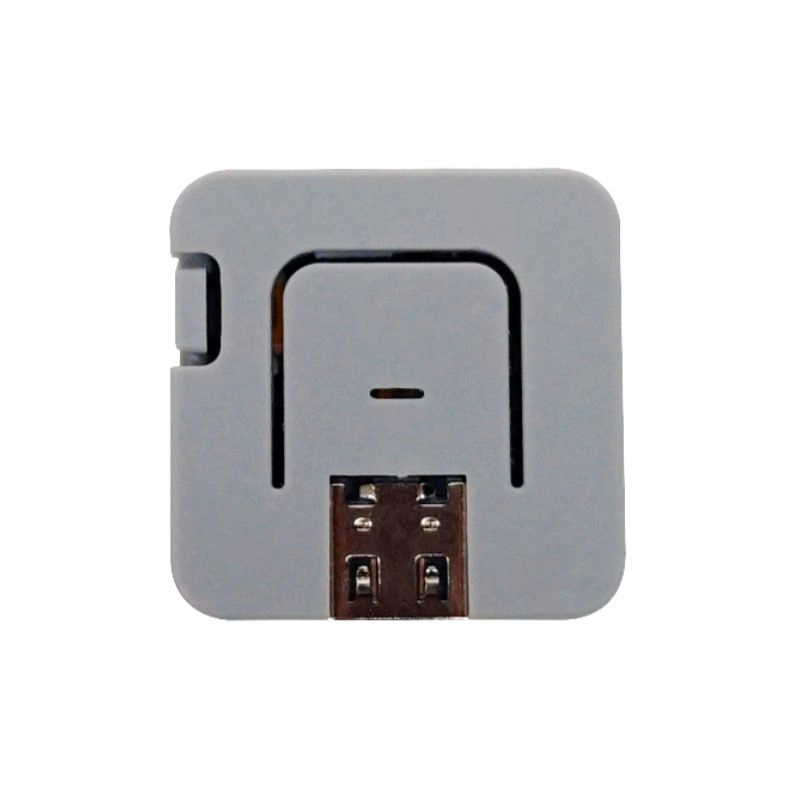
- Required hardware products:
2.Example Program
Compilation Requirements
M5Stack Board Package Version >= 3.2.2
M5Unified Library Version >= 0.2.7
M5GFX Library Version >= 0.2.9
M5Unified Library Version >= 0.2.7
M5GFX Library Version >= 0.2.9
cpp
1 2 3 4 5 6 7 8 9 10 11 12 13 14 15 16 17 18 19 20 21 22 23 24 25 26 27 28 29 30 31 32 33 34 35 36 37 38
#include <M5UnitGLASS2.h>
#include <M5Unified.h>

#define M5UNITGLASS2_ADDR 0x3C  // For Unit Glass2, 0x3C is default, and 0x3D is modified.

int index_unit_glass2;

void setup() {
  auto cfg = M5.config();
  cfg.external_display.unit_glass2 = true;
  M5.begin(cfg);

  index_unit_glass2 = M5.getDisplayIndex(m5::board_t::board_M5UnitGLASS2);
  M5.Displays(index_unit_glass2).setTextSize(2);
  M5.Displays(index_unit_glass2).clear();
}

void loop() {
  M5.Displays(index_unit_glass2).setCursor(0, 0);
  M5.Displays(index_unit_glass2).print("This is \nUnit \nGlass2");
  delay(1000);
  M5.Displays(index_unit_glass2).clear();

  M5.Displays(index_unit_glass2).drawRect(0, 0, 128, 64, 0xFFFF);  // x, y, w, h, color
  delay(500);
  M5.Displays(index_unit_glass2).drawCircle(20, 20, 15, 0xFFFF);  // x, y, r, color
  delay(500);
  M5.Displays(index_unit_glass2).fillArc(50, 45, 17, 20, 100, 330, 0xFFFF);  // x, y, r0, r1, angle0, angle1, color
  delay(500);
  M5.Displays(index_unit_glass2).fillRect(45, 10, 25, 10, 0xFFFF);  // x, y, w, h, color
  delay(500);
  M5.Displays(index_unit_glass2).fillTriangle(90, 10, 80, 40, 110, 55, 0xFFFF);  // x0, y0, x1, y1, x2, y2, color
  delay(500);
  M5.Displays(index_unit_glass2).drawLine(110, 0, 128, 64, 0xFFFF);  // x0, y0, x1, y1, color
  delay(1000);

  M5.Displays(index_unit_glass2).clear();
}Runtime Effect:
3.I2C Address Modification
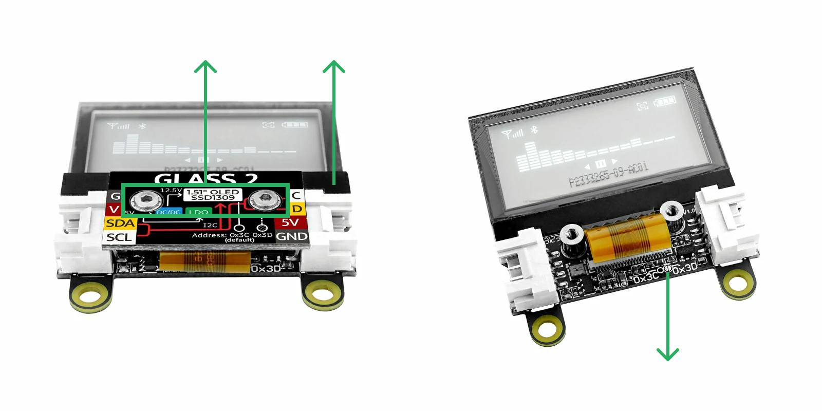
As shown in the image above, use a hex wrench to remove the two screws, then lift the cover plate upwards. Gently push aside the display ribbon cable to reveal the two semicircular solder pads inside the circle. Solder a bridge between the two pads to change the I2C address to 0x3D. To revert to the default address 0x3C, remove the solder bridge.
If the I2C address is changed to 0x3D, you need to add the macro definition #define M5UNITGLASS2_ADDR 0x3D in your program. The two HY2.0-4P Grove ports are interconnected and can be used interchangeably to connect other I2C devices.
4.API
Page Tools