


Arduino Quick Start
2. Devices & Examples
3. M5Unified
4. M5GFX
5. Extensions
Unit
Atomic
Tab5
IoT
Accessories
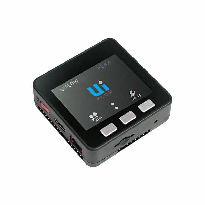
Module13.2 QRCode Arduino Tutorial
1. Preparation
- Environment setup: Refer to the Arduino IDE Getting Started Tutorial to complete the IDE installation, and install the corresponding board package and required libraries according to the development board you are using.
- Libraries used:
- Hardware used:
2. Notes
3. Example Program
In this tutorial, the Basic v2.7 core is paired with the Module13.2 QRCode to implement 1-D/2-D code recognition. Before use, please refer to the figure below and set the DIP switches to the specified positions.
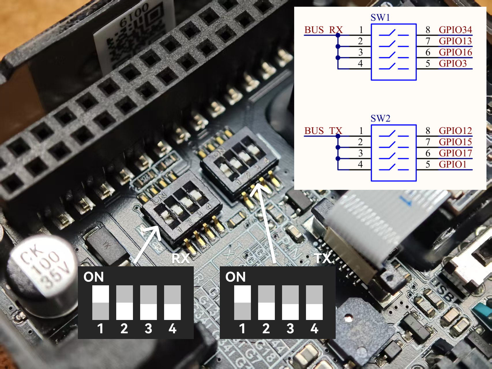
3.1 DIP Switch for Pin Selection
This example pairs the Basic v2.7 core with the Module13.2 QRCode and uses G34 (RX) and G12 (TX) as communication pins. The specific DIP-switch settings are shown below.
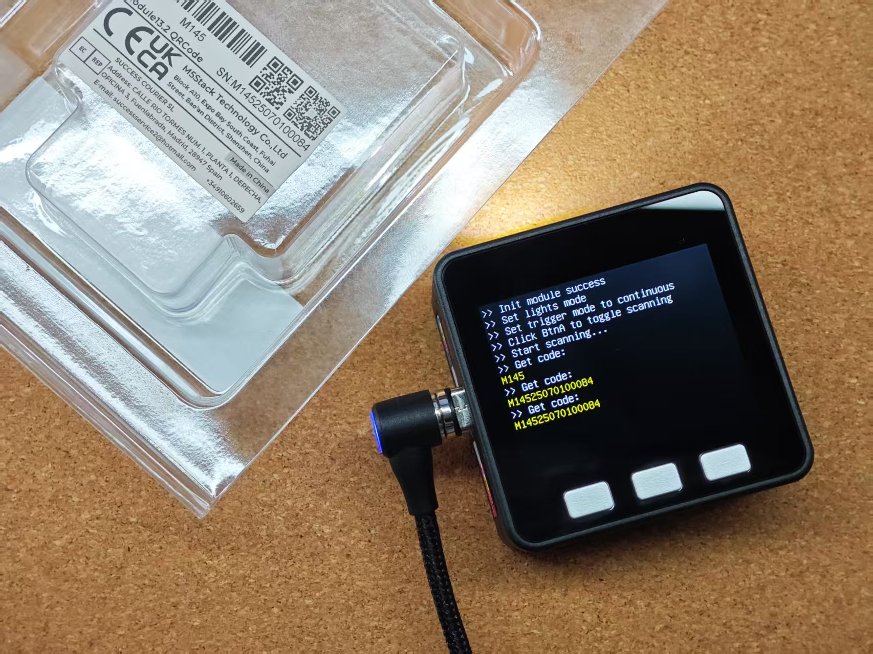
3.2 Basic Scanning Example
This example sets the Module13.2 QRCode to key-triggered scan mode. Clicking Button A sends the start/stop scan commands via UART. Holding down Button B controls scanning through the module’s TRIG pin (low level to start scanning, high level to stop). After a successful scan, the decoded result is displayed on the screen.
/*
 * SPDX-FileCopyrightText: 2025 M5Stack Technology CO LTD
 *
 * SPDX-License-Identifier: MIT
 */
#include <Arduino.h>
#include <M5Unified.h>
#include <M5ModuleQRCode.h>

M5ModuleQRCode module_qrcode;

void setup()
{
    M5.begin();
    M5.Display.setFont(&fonts::efontCN_16);
    M5.Display.setTextScroll(true);

    /* Set module config */
    auto cfg     = module_qrcode.getConfig();
    cfg.pin_tx   = 12;
    cfg.pin_rx   = 34;
    cfg.baudrate = 115200;
    cfg.serial   = &Serial1;
    module_qrcode.setConfig(cfg);

    /* Init module */
    while (!module_qrcode.begin()) {
        M5.Display.setTextColor(TFT_RED);
        M5.Display.println(">> Init module failed, retry...");
        delay(1000);
    }
    M5.Display.setTextColor(TFT_WHITE);
    M5.Display.println(">> Init module success");

    /* Set light mode */
    M5.Display.println(">> Set lights mode");
    module_qrcode.setFillLightMode(QRCodeM14::FILL_LIGHT_ON_DECODE);
    module_qrcode.setPosLightMode(QRCodeM14::POS_LIGHT_ON_DECODE);

    /* Set trigger mode */
    M5.Display.println(">> Set trigger mode to continuous");
    module_qrcode.setTriggerMode(QRCodeM14::TRIGGER_MODE_CONTINUOUS);
    module_qrcode.stopDecode();

    M5.Display.println(">> Click BtnA to toggle scanning");
}

void loop()
{
    M5.update();

    static bool is_scanning = false;

    /* If BtnA was clicked */
    if (M5.BtnA.wasClicked()) {
        is_scanning = !is_scanning;

        if (is_scanning) {
            module_qrcode.startDecode();
        } else {
            module_qrcode.stopDecode();
        }

        M5.Display.setTextColor(TFT_WHITE);
        M5.Display.println(is_scanning ? ">> Start scanning..." : ">> Stop scanning");
    }

    /* Update module */
    module_qrcode.update();

    /* If scan result available */
    if (module_qrcode.available()) {
        auto result = module_qrcode.getScanResult();

        /* Display result */
        M5.Display.setTextColor(TFT_WHITE);
        M5.Display.println(">> Get code:");
        M5.Display.setTextColor(TFT_YELLOW);
        M5.Display.println(result.c_str());
    }
}3.3 Scan Trigger Control
The module supports multiple scan-trigger modes.
enum TriggerMode_t {
        TRIGGER_MODE_KEY = 0,
        TRIGGER_MODE_CONTINUOUS = 1,
        TRIGGER_MODE_AUTO = 2,
        TRIGGER_MODE_PULSE = 4,
        TRIGGER_MODE_MOTION_SENSING = 5
};TRIGGER_MODE_KEY:- In key mode, pulling TRIG low triggers a scan. Decoding stops after a successful read. To trigger again, first return TRIG to high, then pull it low again.
TRIGGER_MODE_CONTINUOUS:- In continuous mode, a falling edge on TRIG enters continuous scanning. The module keeps scanning until the next falling edge stops it.
TRIGGER_MODE_AUTO:- In auto mode, the module keeps scanning until another mode is selected. In this mode, scanning cannot be controlled by TRIG or UART commands.
TRIGGER_MODE_PULSE:- In pulse mode, a 20 ms low-level pulse on TRIG triggers a single scan.
TRIGGER_MODE_MOTION_SENSING:- In motion-sensing mode, the module automatically scans based on visual scene changes. Scanning cannot be stopped until another mode is selected. TRIG low is also accepted to trigger scanning.
TRIGGER_MODE_AUTO, the other modes can be controlled via UART commands during operation. 2. Mode settings are stored in the device and remain after power-off.Configure the trigger mode with setTriggerMode:
module_qrcode.setTriggerMode(QRCodeM14::TRIGGER_MODE_KEY);
// module_qrcode.setTriggerMode(QRCodeM14::TRIGGER_MODE_CONTINUOUS);
// module_qrcode.setTriggerMode(QRCodeM14::TRIGGER_MODE_AUTO);
// module_qrcode.setTriggerMode(QRCodeM14::TRIGGER_MODE_PULSE);
// module_qrcode.setTriggerMode(QRCodeM14::TRIGGER_MODE_MOTION_SENSING);Module13.2 QRCode supports two ways to start scanning:
- Method 1: Call
startDecode()(software trigger via UART command). - Method 2: Call
setTriggerLevel(false)(hardware trigger by pulling TRIG low).
Control scanning with startDecode:
module_qrcode.startDecode();
delay(1000);
module_qrcode.stopDecode();
delay(1000);Control scanning with setTriggerLevel:
module_qrcode.setTriggerLevel(false);
delay(1000);
module_qrcode.setTriggerLevel(true);
delay(1000);3.4 Fill-Light Working Modes
Set the fill-light mode with setFillLightMode(); the enum is defined as:
enum FillLightMode_t {
        FILL_LIGHT_OFF       = 0,  // Light off
        FILL_LIGHT_ON_DECODE = 2,  // Light on during decoding
        FILL_LIGHT_ON        = 3   // Light on
};FILL_LIGHT_OFF: Fill light always offFILL_LIGHT_ON_DECODE: Fill light stays on during decodingFILL_LIGHT_ON: Fill light always on
Configure with setFillLightMode:
module_qrcode.setFillLightMode(QRCodeM14::FILL_LIGHT_ON_DECODE);
// module_qrcode.setFillLightMode(QRCodeM14::FILL_LIGHT_ON);
// module_qrcode.setFillLightMode(QRCodeM14::FILL_LIGHT_OFF);3.5 Position-Light Working Modes
Set the position-light mode with setPosLightMode(); the enum is defined as:
enum PosLightMode_t {
        POS_LIGHT_OFF             = 0,  // Light off
        POS_LIGHT_FLASH_ON_DECODE = 1,  // Light flashing during decoding
        POS_LIGHT_ON_DECODE       = 2   // Light on during decoding
};module_qrcode.setPosLightMode(QRCodeM14::POS_LIGHT_ON_DECODE);
// module_qrcode.setPosLightMode(QRCodeM14::POS_LIGHT_FLASH_ON_DECODE);
// module_qrcode.setPosLightMode(QRCodeM14::POS_LIGHT_OFF);POS_LIGHT_OFF: Position light always offPOS_LIGHT_FLASH_ON_DECODE: Position light flashes during decodingPOS_LIGHT_ON_DECODE: Position light stays on during decoding
4. USB Modes
Module13.2 QRCode supports multiple USB working modes, including USB-CDC, USB HID Keyboard, and USB HID-POS.
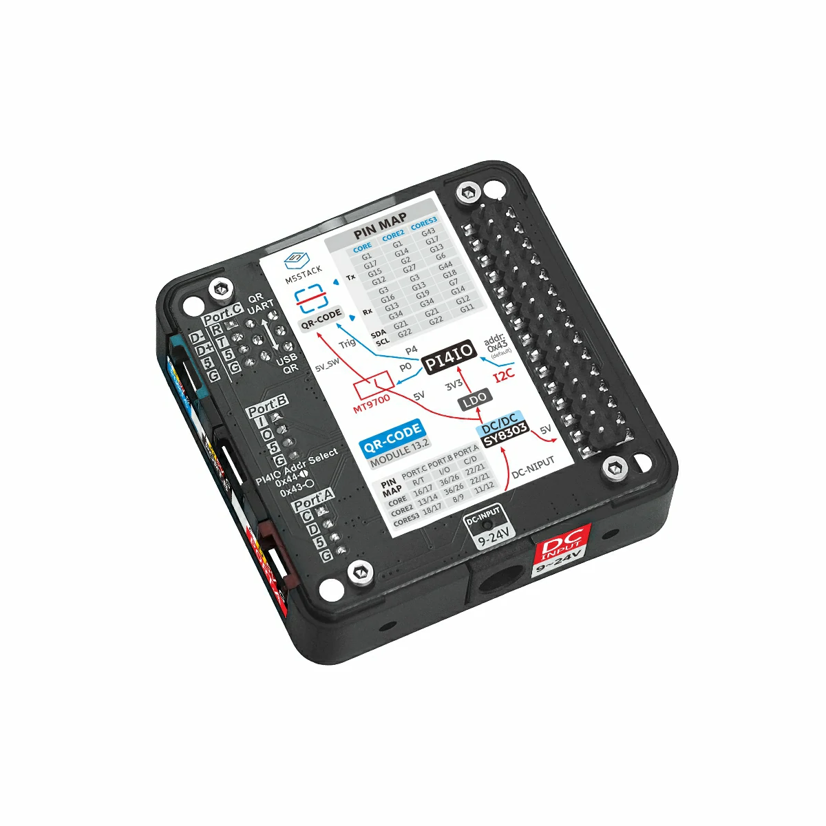
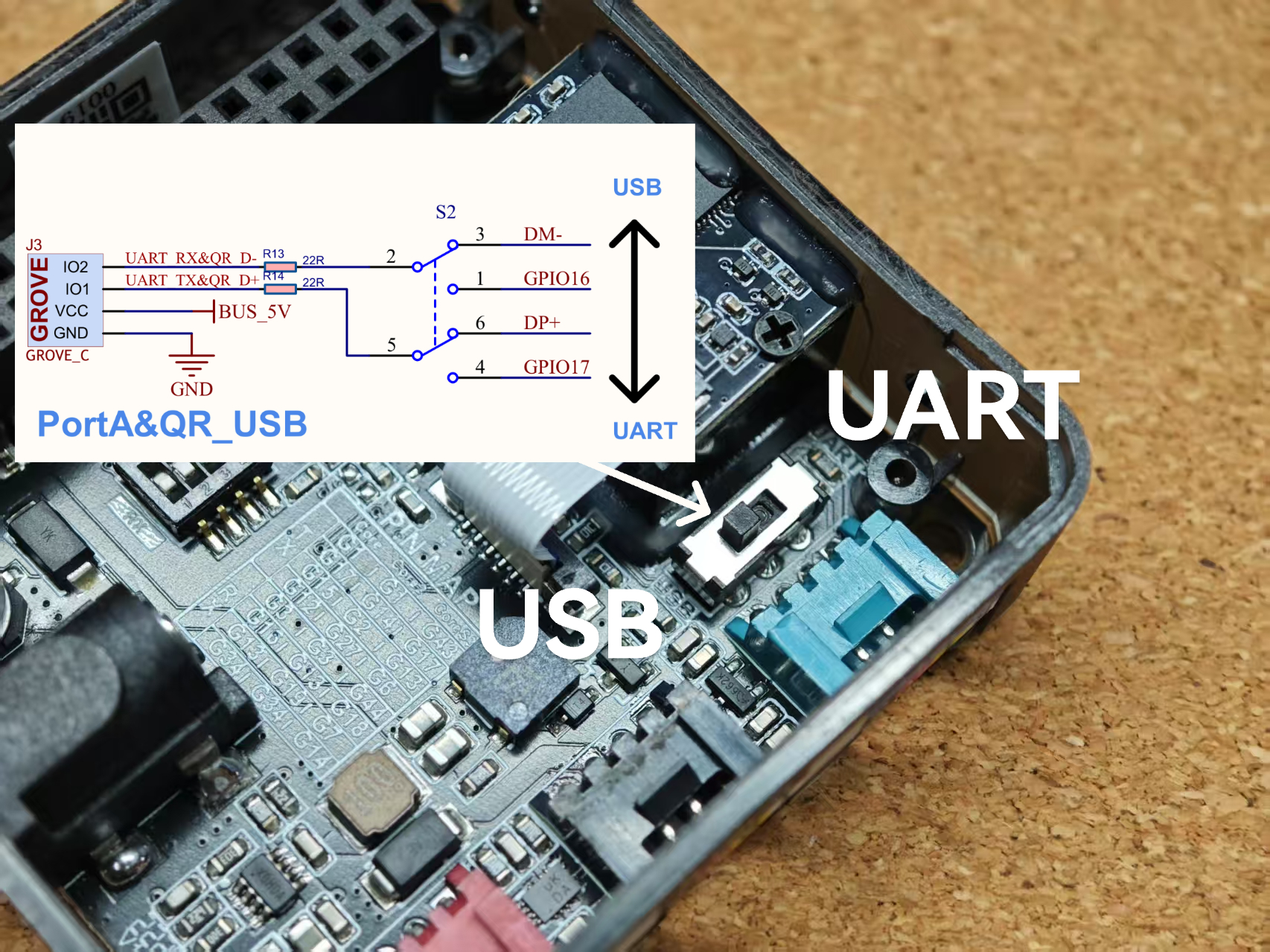
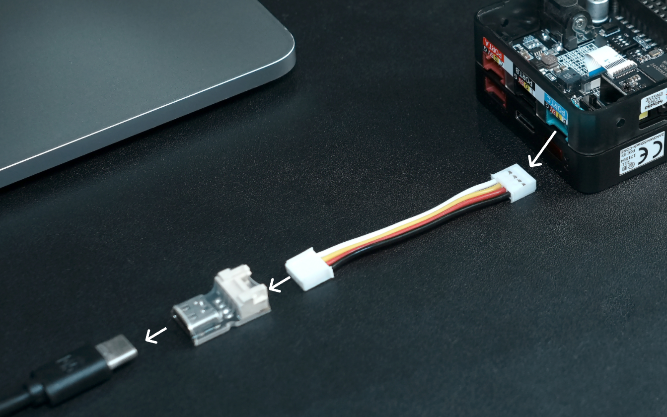
4.1 USB/UART Interface Switching
Before use, flip the on-board interface switch to the USB side. This connects the module’s USB_D+ and USB_D- pins to PORT.C. Then use a Grove to USB-C adapter board to connect PORT.C to a PC. Refer to the example programs below to configure the desired USB mode.

4.2 USB-CDC
Call setModeUsbSerial() to enter USB-CDC mode. After connecting to a PC, a virtual serial port appears. Use a serial monitor or terminal tool to connect, hold Button A to scan, and view results in the terminal. UART commands are also available. To return to UART mode, send the HEX values 21 42 40 00 (serial-port configuration command). The QR module blinks briefly to indicate success, and the USB-CDC interface closes.
/* (code block remains unchanged) */4.3 USB-HID
Call setModeUsbKeyboard() to enter USB-HID mode. The device emulates a USB keyboard. Hold Button A to scan; the decoded result is output as keyboard input.
4.4 USB-HID POS
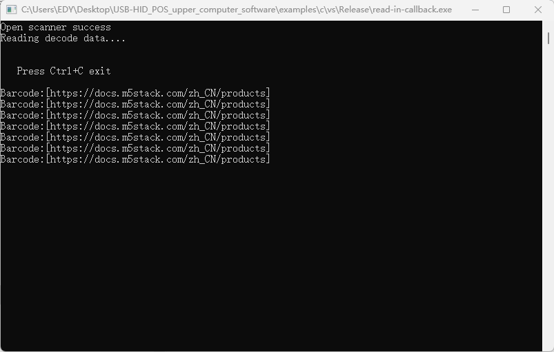
Call setModeUsbPos() to enter USB-HID POS mode. The device emulates a standard POS barcode scanner. This mode requires a host application with the standard protocol. Currently, only a Windows host is provided; other platforms can port the source code.
Run examples\c\vs\Release\read-in-callback.exe in the package and scan a test QR code; the result appears in the host window.
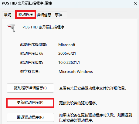
4.5 USB HID-POS Driver Error Solution
If a driver error appears in Device Manager when using USB HID-POS:
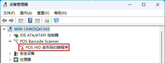
Follow these steps:
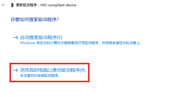
- Double-click the faulty driver, open the “Driver” tab, click “Update Driver,” and choose “Browse my computer for driver software.”
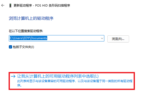
- Select “Let me pick from a list of available drivers on my computer,” choose “HID-compliant device,” and click “Next.” When the final page appears, the driver update is complete.
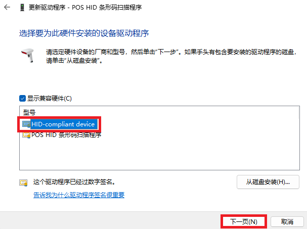
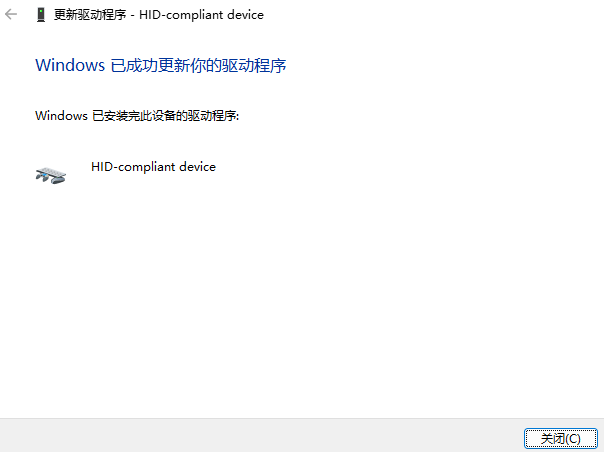
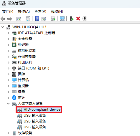
When “HID-compliant device” appears in Device Manager, USB HID-POS works correctly.
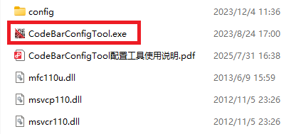
5. PC Configuration Tool
Download and open CodeBarConfigTool.exe; the tool interface is shown below.
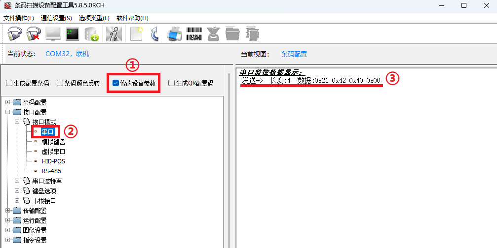
The example below shows how to switch from USB-CDC to UART mode:
First, click icon ①, select the corresponding USB port at ②, and click “Connect” at ③. When ④ shows “Online,” the connection is successful.

Next, tick box ①, locate item ② and double-click it. When the configuration information shown at ③ appears, UART mode is configured successfully.
For detailed instructions, refer to CodeBarConfigTool.pdf in the software package.