Arduino Quick Start
2. Devices & Examples
3. M5Unified
4. M5GFX
5. Extensions
Unit
Atomic
Tab5
IoT
Accessories
Unit Step16 Arduino Tutorial
1. Preparations
- Environment Setup: Refer to the Arduino IDE Getting Started Tutorial to complete IDE installation, and install the corresponding board manager and required libraries based on the actual development board being used.
- Required Libraries:
Note
You need to download the latest library version from GitHub: M5Unit-Step16 - M5Stack GitHub. Do not download from the Arduino Library Manager. (For reference, see this tutorial)
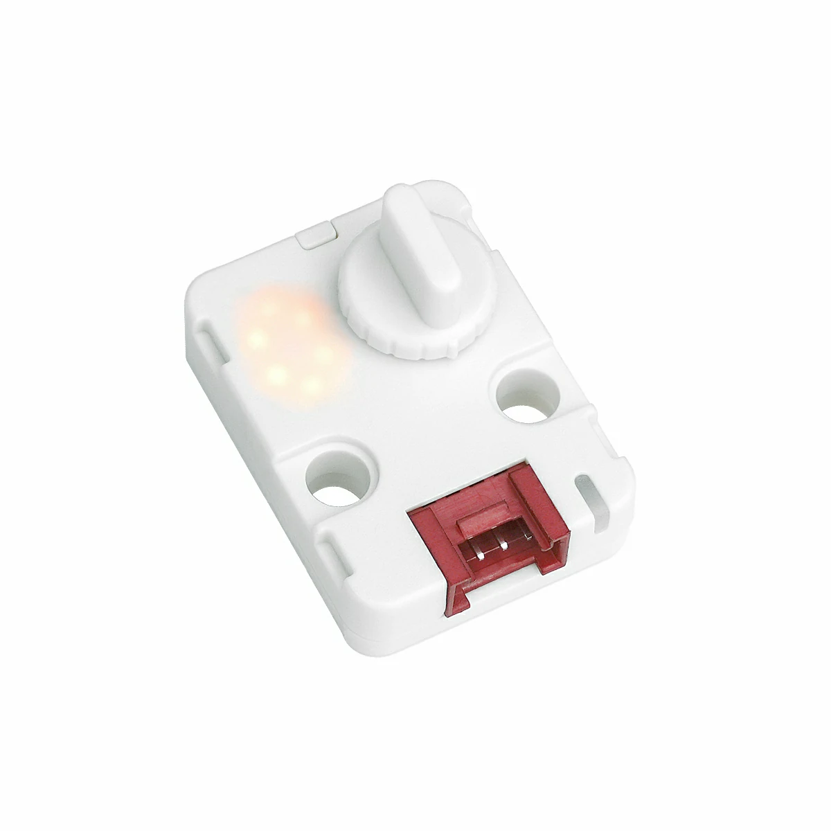
- Required Hardware Products:

2. Important Notes
Pin Compatibility
Since each host device has different pin configurations, M5Stack officially provides a Pin Compatibility Table for user convenience. Please modify the example program according to your actual pin connections.
3. Example Program
- The main controller used in this tutorial is CoreS3 paired with Unit Step16. This 16-step rotary encoder module communicates via I2C. Modify the pin definitions in the program according to your actual circuit connections. The default I2C pins for this device connection are
G1 (SCL)andG2 (SDA).
cpp
1 2 3 4 5 6 7 8 9 10 11 12 13 14 15 16 17 18 19 20 21 22 23 24 25 26 27 28 29 30 31 32 33 34 35 36 37 38 39 40 41 42 43 44 45 46 47 48 49 50 51 52 53 54 55 56 57 58 59 60 61 62 63 64 65 66 67 68 69 70 71 72 73 74 75 76 77 78 79 80 81 82 83 84 85 86 87 88 89 90 91 92 93 94 95 96 97 98 99 100 101 102 103 104 105 106 107 108 109 110 111 112 113 114 115 116 117 118 119 120 121 122 123 124 125 126 127 128 129 130 131 132 133 134 135 136 137 138 139 140 141 142 143 144 145 146
/*
* SPDX-FileCopyrightText: 2025 M5Stack Technology CO LTD
*
* SPDX-License-Identifier: MIT
*/
/*
* @Hardwares: M5Stack PortA device + Unit Step16
* @Dependent Library:
* M5Unit-Step16:https://github.com/m5stack/M5Unit-Step16
* @description: When the knob is rotated, only 0-8 is displayed,
* when raw value reaches 9-F, rotation direction is automatically reversed,
* LED brightness follows display value, never zero (minimum 10%),
* RGB color follows the 0-8 pattern
*/
#include <M5Unified.h>
#include <M5UnitStep16.h>
#define I2C_SDA_PIN (2)
#define I2C_SCL_PIN (1)
#define NUM_DIGITS (9)
#define MAX_DIGIT (8)
#define MIN_DIGIT (0)
#define MIN_BRIGHTNESS (10)
#define MAX_BRIGHTNESS (100)
#define BRIGHTNESS_STEP (10)
#define RGB_BRIGHTNESS (70)
#define LED_ALWAYS_ON (0xFF)
UnitStep16 step16;
uint8_t currentDigit = 0;
uint8_t lastRawValue = 0;
bool isFirstRead = true;
const uint8_t digitBrightness[NUM_DIGITS] = {
MIN_BRIGHTNESS, // 0 - 10%
MIN_BRIGHTNESS + BRIGHTNESS_STEP, // 1 - 20%
MIN_BRIGHTNESS + BRIGHTNESS_STEP * 2, // 2 - 30%
MIN_BRIGHTNESS + BRIGHTNESS_STEP * 3, // 3 - 40%
MIN_BRIGHTNESS + BRIGHTNESS_STEP * 4, // 4 - 50%
MIN_BRIGHTNESS + BRIGHTNESS_STEP * 5, // 5 - 60%
MIN_BRIGHTNESS + BRIGHTNESS_STEP * 6, // 6 - 70%
MIN_BRIGHTNESS + BRIGHTNESS_STEP * 7, // 7 - 80%
MIN_BRIGHTNESS + BRIGHTNESS_STEP * 8 // 8 - 90%
};
struct MyRGBColor {
uint8_t r, g, b;
const char* name;
};
const MyRGBColor digitColors[NUM_DIGITS] = {
{0, 0, 128, "Deep Blue"}, // 0 - cold color
{0, 64, 192, "Blue"}, // 1
{0, 128, 255, "Light Blue"}, // 2
{0, 192, 192, "Cyan"}, // 3
{0, 255, 128, "Cyan Green"}, // 4
{128, 255, 0, "Yellow Green"}, // 5
{192, 192, 0, "Yellow"}, // 6
{255, 128, 0, "Orange"}, // 7
{255, 64, 0, "Orange Red"} // 8 - warm color
};
uint8_t mapRawValueToDigit(uint8_t rawValue);
void updateDisplay(uint8_t digit);
uint8_t mapRawValueToDigit(uint8_t rawValue);
void updateDisplay(uint8_t digit);
void handleValueChange(uint8_t oldVal, uint8_t newVal);
void setup()
{
M5.begin();
Serial.begin(115200);
Wire.begin(I2C_SDA_PIN, I2C_SCL_PIN);
while(!step16.begin()){
delay(1000);
Serial.println("M5Unit-Step16 not found!");
}
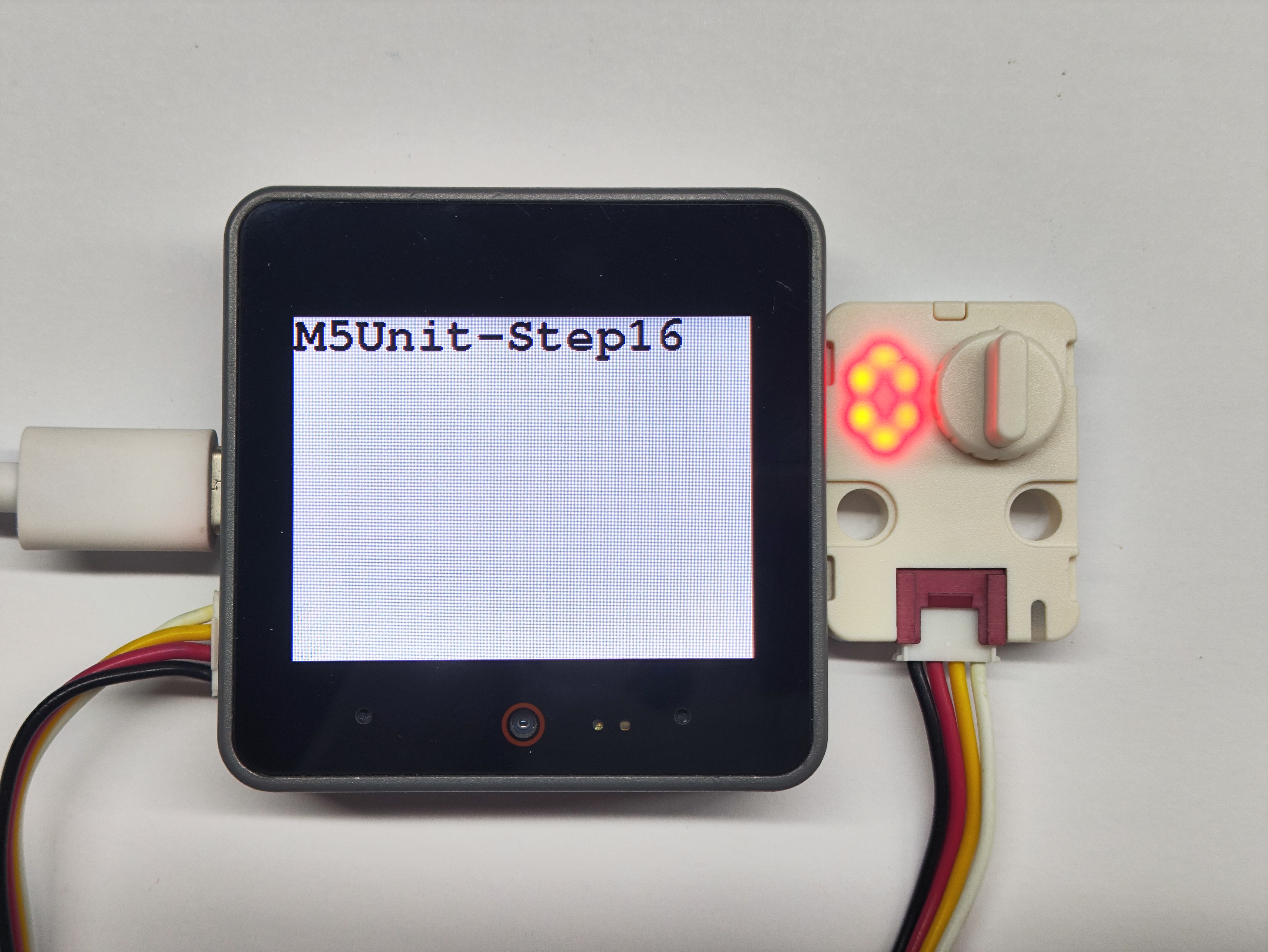
M5.Display.fillRect(0, 0, 320, 240, WHITE);
M5.Display.setTextColor(BLACK);
M5.Display.setFont(&fonts::FreeMonoBold18pt7b);
M5.Display.setCursor(0, 0);
M5.Display.printf("M5Unit-Step16\n");
step16.setRgbConfig(1);
step16.setRgbBrightness(RGB_BRIGHTNESS);
lastRawValue = step16.getValue();
currentDigit = mapRawValueToDigit(lastRawValue);
updateDisplay(currentDigit);
}
void loop()
{
uint8_t rawValue = step16.getValue();
if (rawValue != lastRawValue && !isFirstRead) {
handleValueChange(lastRawValue, rawValue);
lastRawValue = rawValue;
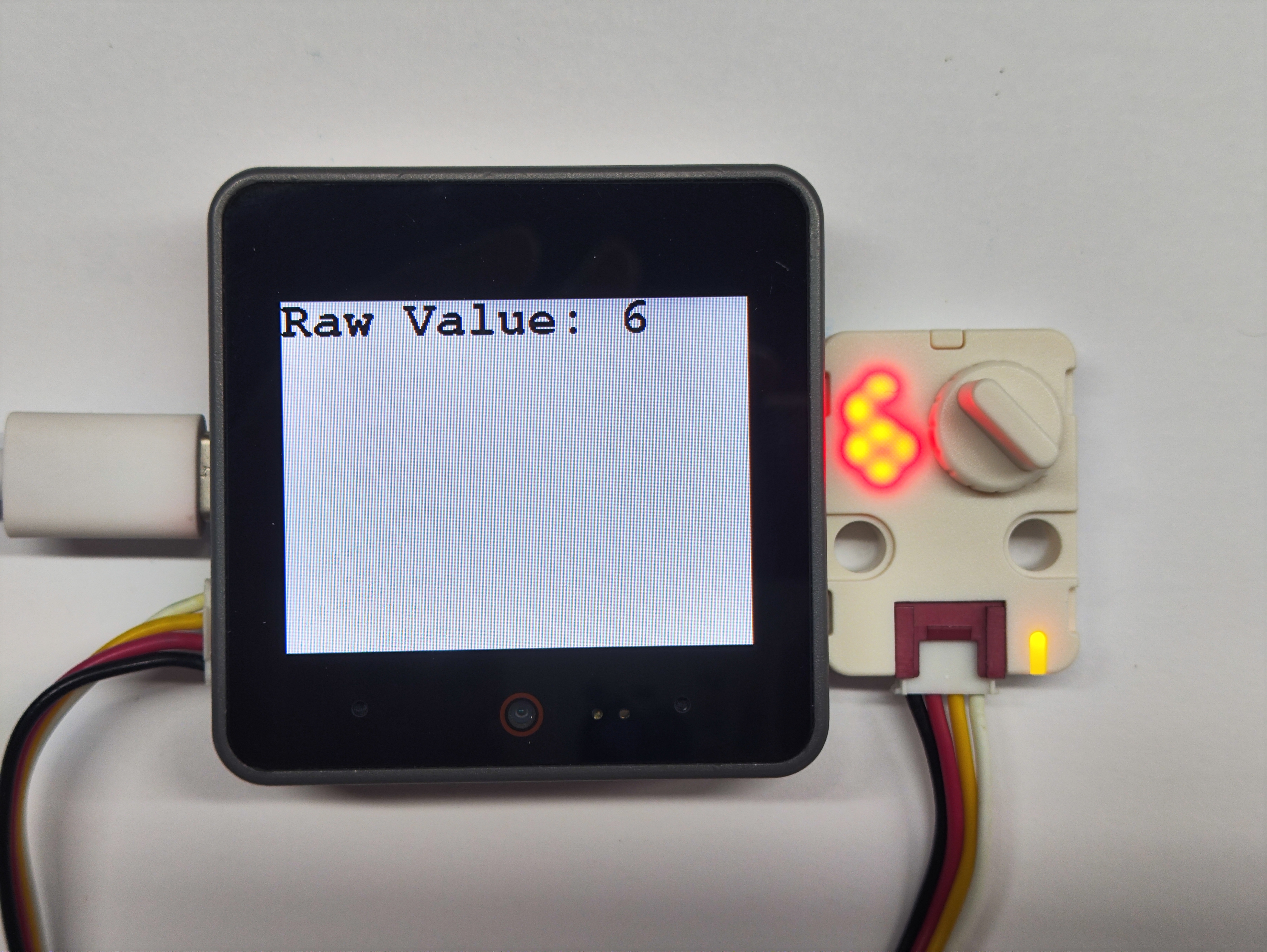
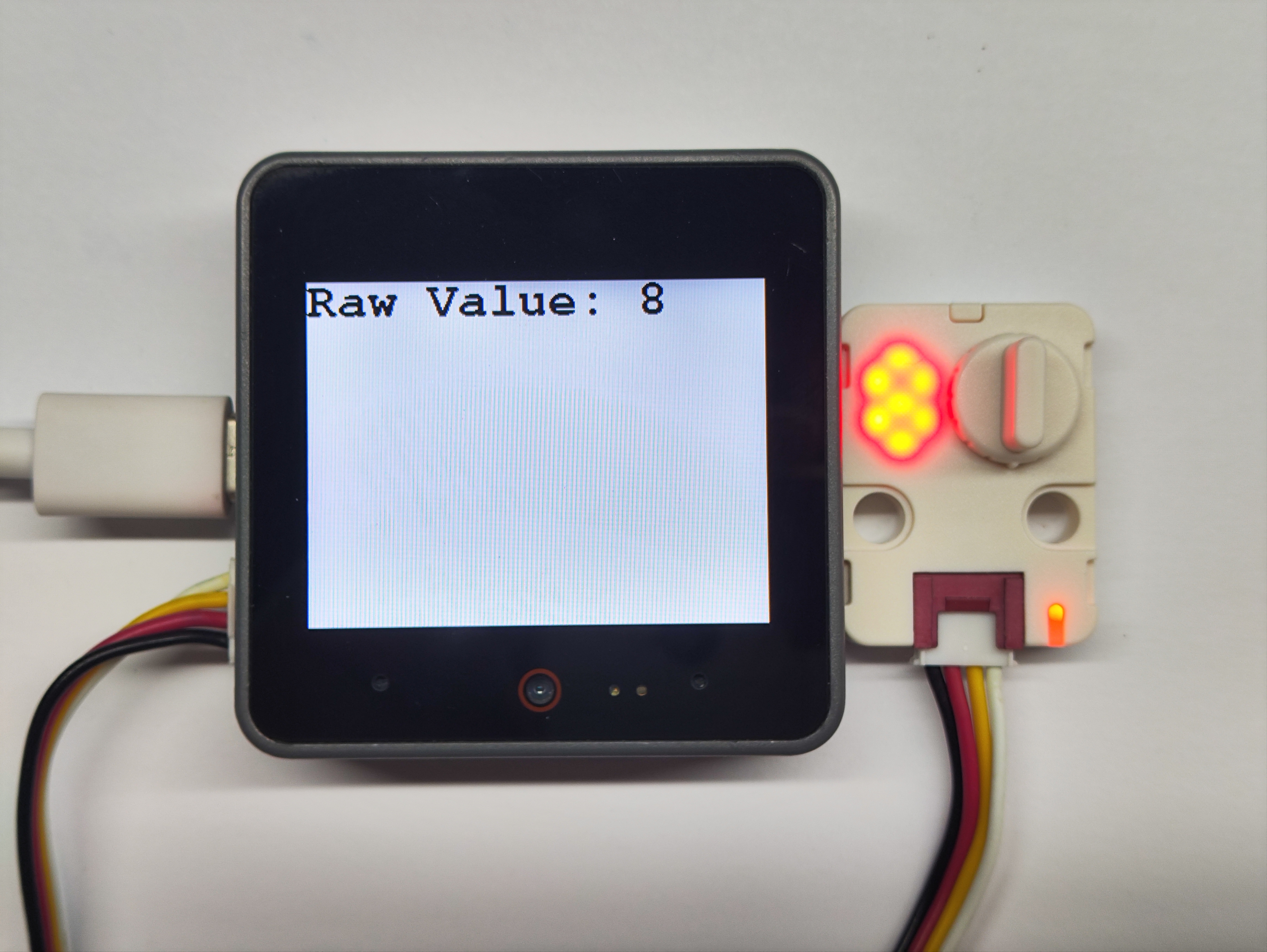
M5.Display.fillRect(0, 0, 320, 240, WHITE);
M5.Display.setCursor(0, 0);
M5.Display.printf("Raw Value: %d\n", rawValue);
}
if (isFirstRead) isFirstRead = false;
delay(50);
}
/**
* @brief Handle value change
* @param oldVal Old raw value
* @param newVal New raw value
*/
void handleValueChange(uint8_t oldVal, uint8_t newVal)
{
if (newVal >= 9 && newVal <= 15) {
uint8_t currentDirection = step16.getSwitchState();
step16.setSwitchState(currentDirection == 0 ? 1 : 0);
}
uint8_t newDigit = mapRawValueToDigit(newVal);
if (newDigit != currentDigit) {
currentDigit = newDigit;
updateDisplay(currentDigit);
}
}
/**
* @brief Map raw value to digit 0-8
* @param rawValue Raw value (0-15)
* @return Mapped digit (0-8)
*/
uint8_t mapRawValueToDigit(uint8_t rawValue)
{
if (rawValue <= 8) {
return rawValue;
} else {
return 17 - rawValue;
}
}
/**
* @brief Update display
* @param digit Digit to display (0-8)
*/
void updateDisplay(uint8_t digit)
{
if (digit > MAX_DIGIT) return;
step16.setLedBrightness(digitBrightness[digit]);
step16.setRgb(digitColors[digit].r, digitColors[digit].g, digitColors[digit].b);
step16.setLedConfig(LED_ALWAYS_ON);
}4. Compile and Upload
Download Mode: The device needs to enter download mode before programming. This process may vary depending on the main controller. For details, refer to the device programming tutorial list at the bottom of the Arduino IDE Getting Started Tutorial page for specific instructions.
For CoreS3: Press and hold the reset button (about 2 seconds) until the internal green LED lights up, then release. The device is now in download mode and ready for programming.
.gif)
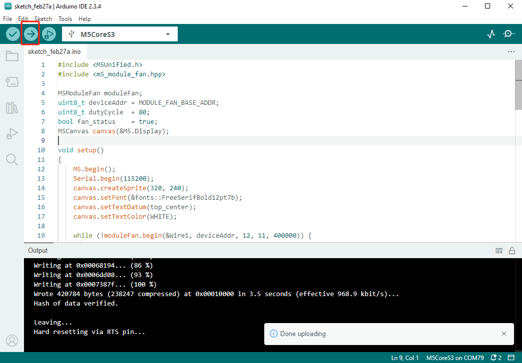
- Select the device port, then click the upload button in the top-left corner of Arduino IDE. Wait for the program to complete compilation and upload to the device.
5. Nixie Tube Display
- The initial state of the program shows 0 on the nixie tube. When rotating the knob, the number on the tube will change accordingly, and the RGB light color will also change.