

Arduino Quick Start
2. Devices & Examples
3. M5Unified
4. M5GFX
5. Extensions
Unit
Atomic
Tab5
IoT
Accessories
Unit AIN4-20mA Arduino Tutorial
1. Preparations
- Environment Setup: Refer to Arduino IDE Getting Started Guide to complete IDE installation, and install corresponding board manager and required driver libraries based on the development board used.
- Required Driver Libraries:
- M5Unified
- M5GFX
- M5Module-4-20mA(This module shares the same driver library with Module13.2 AIN4-20mA)
Note
Download the latest library version from GitHub: M5Module-4-20mA - M5Stack GitHub. Do not download from Arduino Library. (For questions, refer to this tutorial)
- Required Hardware Products:

2. Precautions
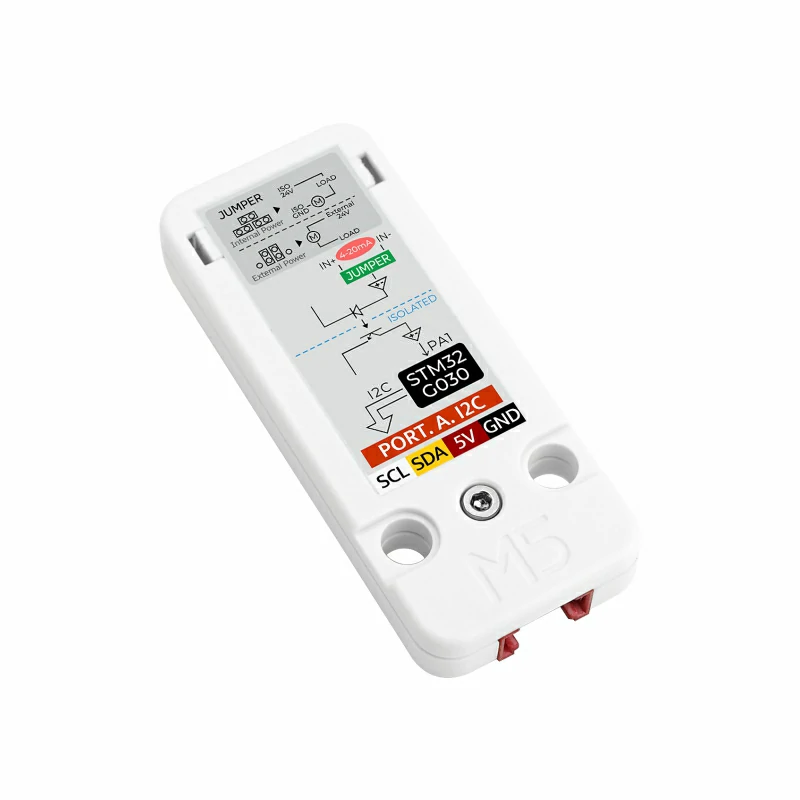
Jumper Cap Connection Guide
The product package includes 3 jumper caps for switching between passive/active current sensors.
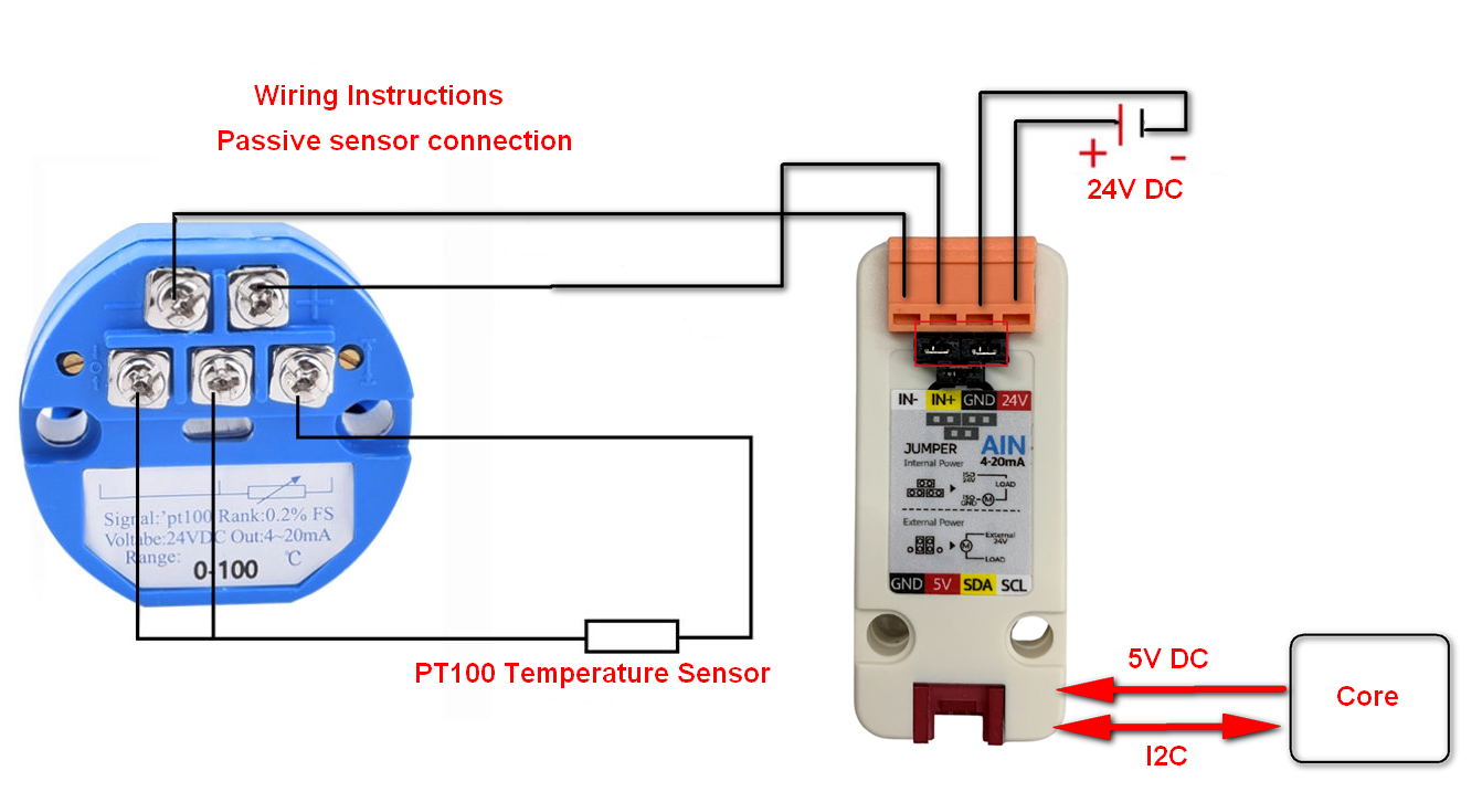
- For passive current sensors: Connect DC 24V power supply, sensor signals to IN+/IN-, and set jumper caps as shown below (note polarity):
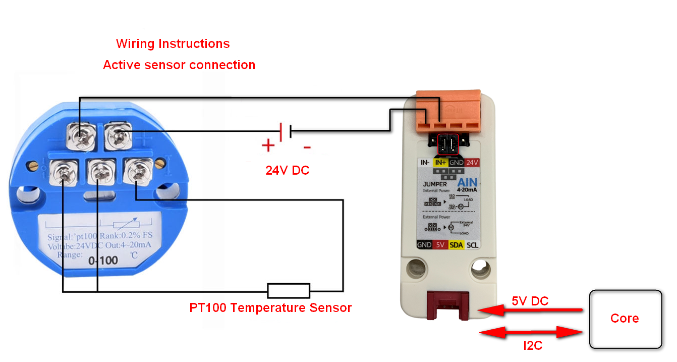
- For active current sensors: Connect sensor signals to IN+/IN-, and set jumper caps as shown below (note polarity):
Pin Compatibility
Since pin configurations vary across host devices, please refer to the Pin Compatibility Table in the product documentation before use, and modify the sample program according to actual pin connections.
3. Sample Program
- The main control device used in this tutorial is CoreS3 paired with Unit AIN4-20mA. This current-type analog acquisition module communicates via I2C. Modify the pin definitions in the program according to the actual circuit connections. After device connection, the corresponding serial IOs are
G1 (SCL)andG2 (SDA).
cpp
1 2 3 4 5 6 7 8 9 10 11 12 13 14 15 16 17 18 19 20 21 22 23 24 25 26 27 28 29 30 31 32
#include <M5Unified.h>
#include "MODULE_4_20MA.h"
#include <M5GFX.h>

MODULE_4_20MA meter;

void show_current_value(void) {
    M5.Display.fillScreen(WHITE);
    M5.Display.setCursor(0, 0);
    M5.Display.println("Unit 4-20mA Demo");
    M5.Display.setCursor(0, 50);
    M5.Display.printf("Current:%.2fmA\r\n", (float)(meter.getCurrentValue(0)) / 100.0);
    M5.Display.printf("ADC_Value:%.2f\r\n", (float)(meter.getADC12BitsValue(0)) / 100.0);
    M5.Display.printf("Cal_Current:%.2fmA", (float)(meter.getCurrentValue(0)));
}

void setup() {
    M5.begin();
    Serial.begin(115200);
    M5.Display.fillScreen(WHITE);
    M5.Display.setTextColor(BLACK);
    M5.Display.setFont(&fonts::FreeMonoBold12pt7b);
    M5.Display.setCursor(0, 0);
    while (!(meter.begin(&Wire, MODULE_4_20MA_ADDR, 2, 1, 100000UL))) {
        M5.Display.println("No Module!");
    }
}

void loop() {
    show_current_value();
    delay(1000);
}4. Compile and Upload
Download Mode: Different devices require entering download mode before program burning. This step may vary depending on the main control device. For details, refer to the device program download tutorial list at the bottom of the Arduino IDE Getting Started Guide page for specific operations.
For CoreS3: Press and hold the reset button (about 2 seconds) until the internal green LED lights up, then release. The device will now enter download mode and wait for burning.
.gif)
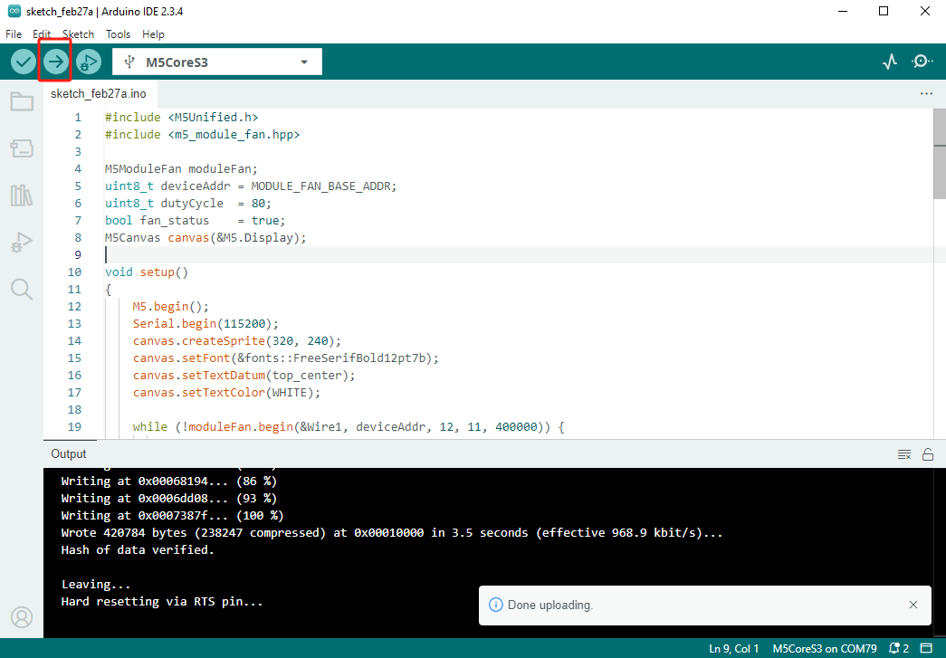
- Select the device port and click the compile/upload button in the top-left corner of Arduino IDE. Wait for the program to complete compilation and upload to the device.
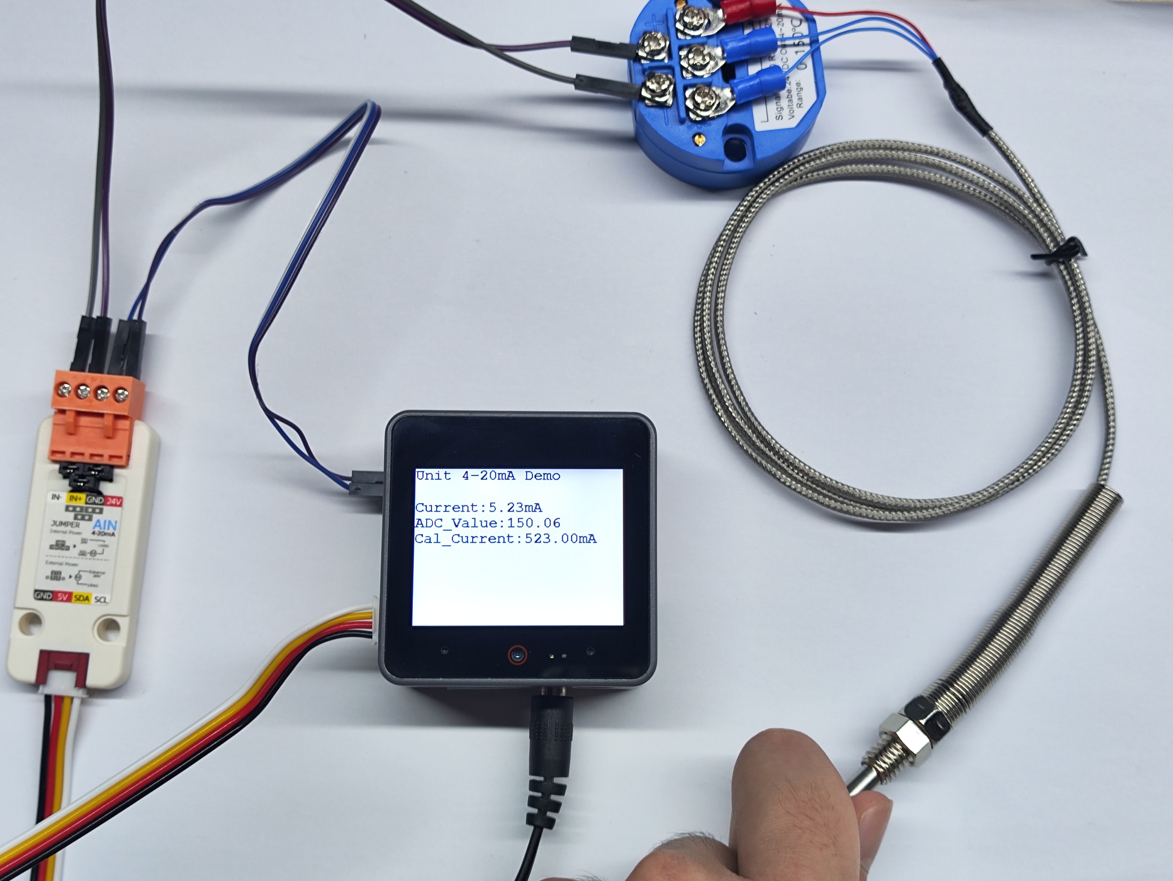
5. Current Acquisition
- This experiment uses a PT100 thermocouple temperature sensor with a passive current-type sensor. After completing hardware wiring, burn the code to see the acquired current analog data.
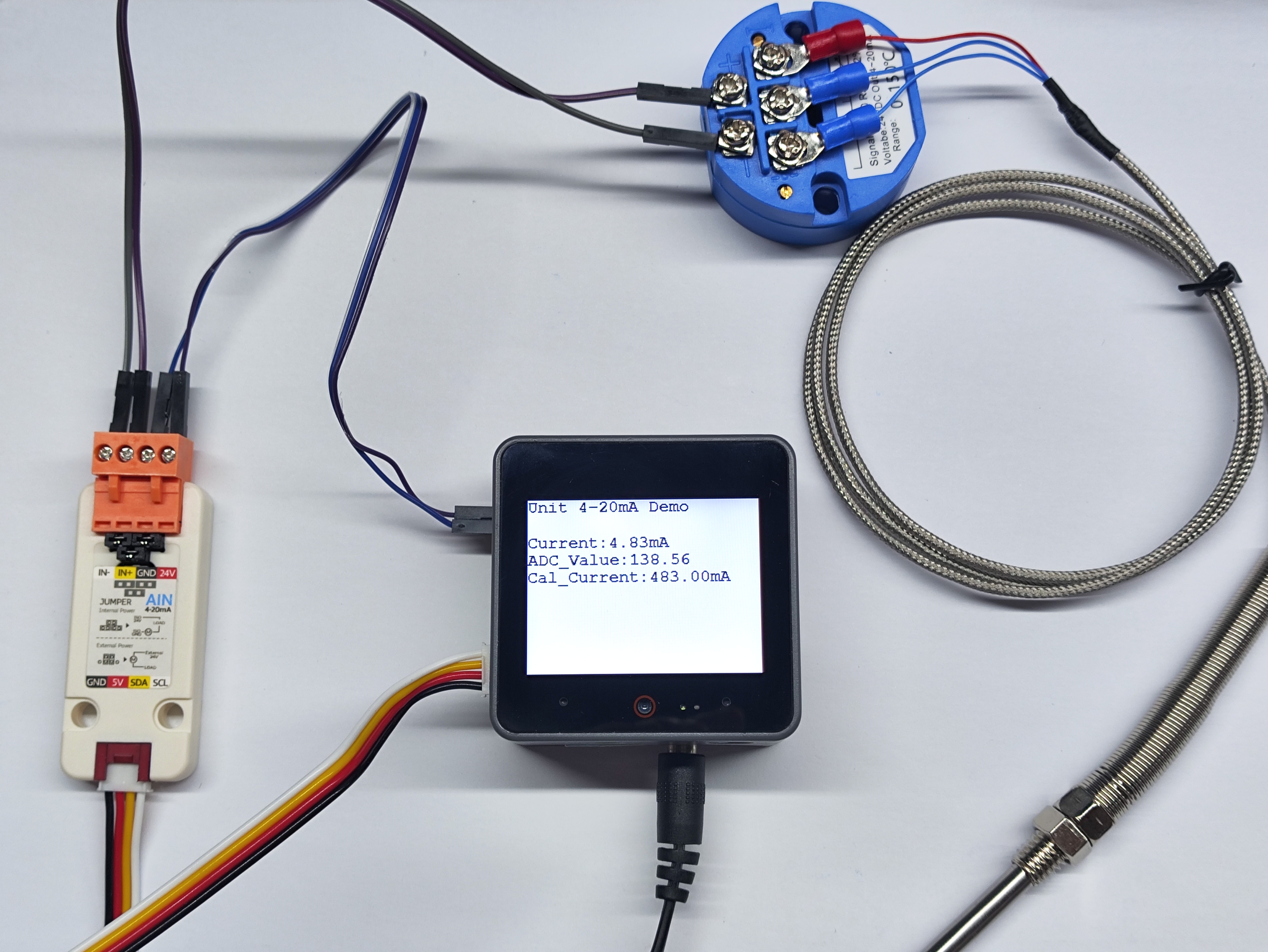
- When the sensor temperature rises, the current value obtained by the current sensor also increases.
Page Tools