


Arduino Quick Start
2. Devices & Examples
3. M5Unified
4. M5GFX
5. Extensions & Examples
Unit
Base
IoT
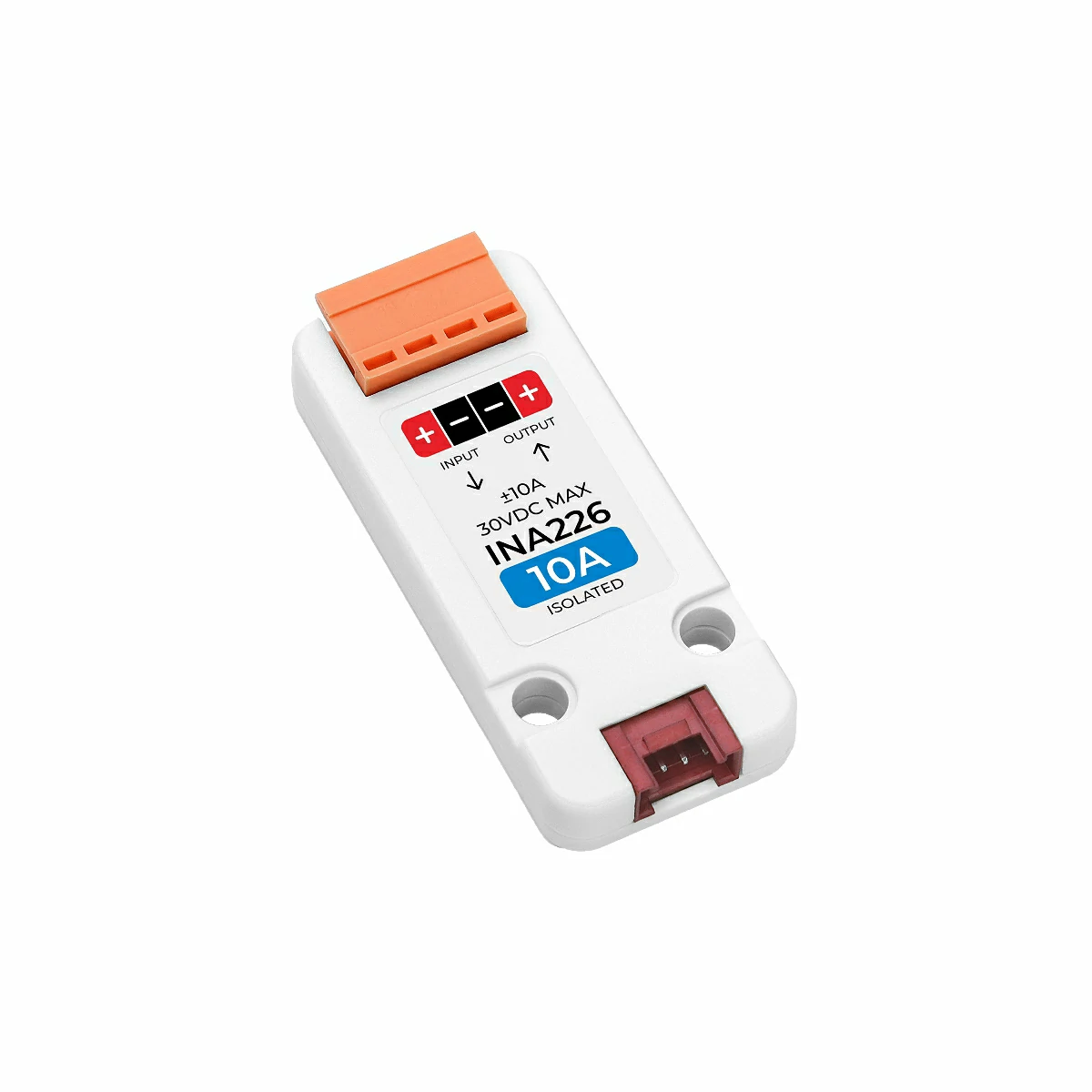
Unit INA226-1A/10A Arduino Tutorial
1. Preparation
- Environment configuration: Refer to Arduino IDE Getting Started Tutorial to complete the IDE installation, install the corresponding board management according to the actual development board used, and the required driver libraries.
- Driver libraries used:
- Hardware products used:
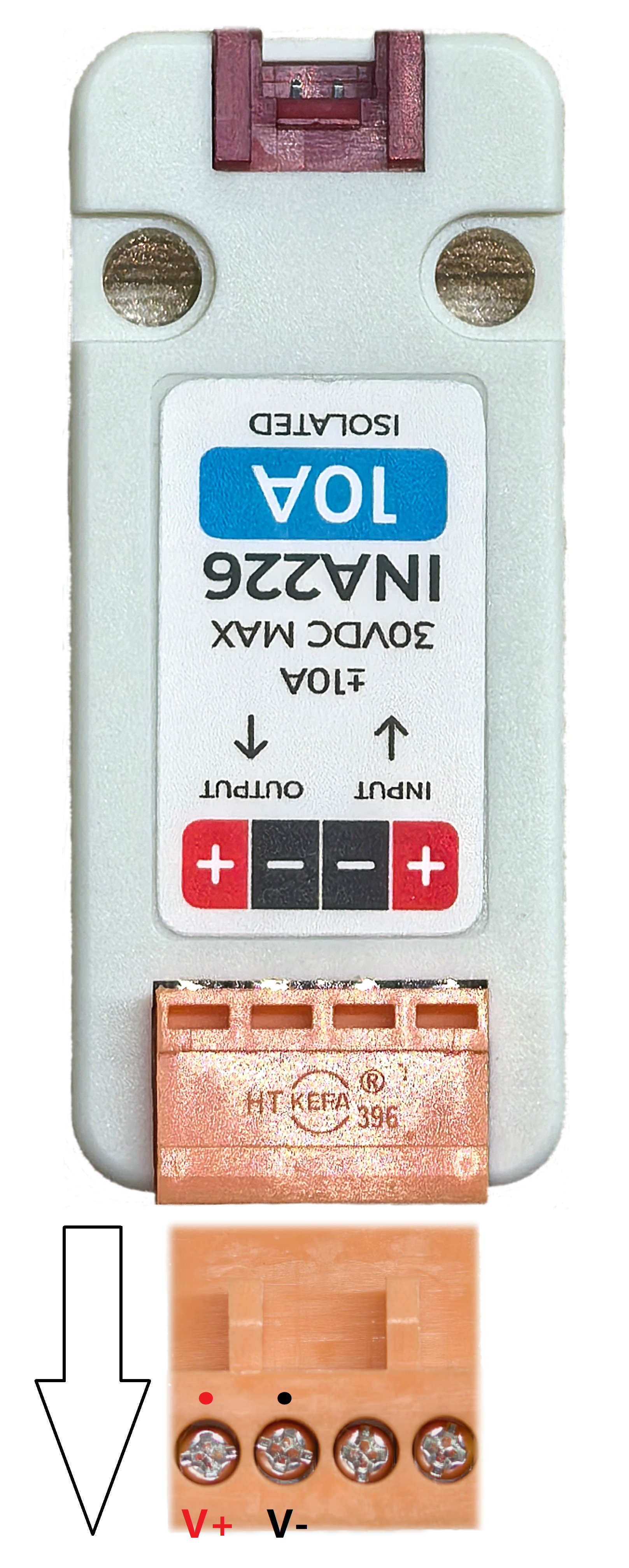
2. Notes
3. Example Program
2.The input power can supply power to the load device through this unit.
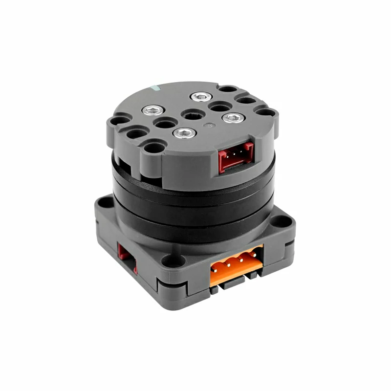
Using Unit Roller485 as an example here, the input power connection is similar. When connecting, please pay attention to matching the correct polarity.
Detection Mode
- Single measurement: Measures instantaneous current, voltage, power, etc., using the
measureSingleshotfunction.
- Single measurement: Measures instantaneous current, voltage, power, etc., using the
- Periodic measurement: Continuously measures current, voltage, power, etc., using the
startPeriodicMeasurementfunction to start, andstopPeriodicMeasurementto stop.
- Periodic measurement: Continuously measures current, voltage, power, etc., using the
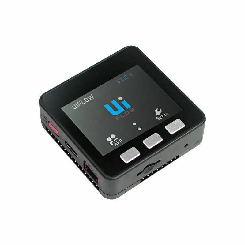
In this tutorial, the host device used is Basic v2.7, paired with Unit INA226-10A (if using Unit INA226-1A, please enable #define USING_UNIT_INA226_1A in the code below) to measure the voltage and current of Unit Roller485.
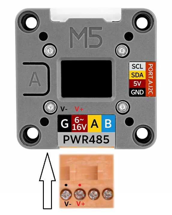
This unit communicates via I2C. Modify the pin definitions in the program according to the actual circuit connections. For the device connections used here, the I2C pins are G22 (SCL) and G21 (SDA).
#include <M5Unified.h>
#include <M5UnitUnified.h>
#include <M5UnitUnifiedMETER.h>
#include <Wire.h>
// *************************************************************
// Choose one define symbol to match the unit you are using
// *************************************************************
#if !defined(USING_UNIT_INA226_1A) && !defined(USING_UNIT_INA226_10A)
// #define USING_UNIT_INA226_1A
#define USING_UNIT_INA226_10A
#endif
namespace {
auto& lcd = M5.Display;
m5::unit::UnitUnified Units;
#if defined(USING_UNIT_INA226_1A)
#pragma message "Using 1A"
m5::unit::UnitINA226_1A unit_ina226;
#elif defined(USING_UNIT_INA226_10A)
#pragma message "Using 10A"
m5::unit::UnitINA226_10A unit_ina226;
#else
#error "Choose unit"
#endif
}  // namespace
void setup()
{
    M5.begin();
    // The screen shall be in landscape mode
    if (lcd.height() > lcd.width()) {
        lcd.setRotation(1);
    }
    auto pin_num_sda = M5.getPin(m5::pin_name_t::port_a_sda);
    auto pin_num_scl = M5.getPin(m5::pin_name_t::port_a_scl);
    M5_LOGI("getPin: SDA:%u SCL:%u", pin_num_sda, pin_num_scl);
    Wire.end();
    Wire.begin(pin_num_sda, pin_num_scl, 400000U);
    if (!Units.add(unit_ina226, Wire) || !Units.begin()) {
        M5_LOGE("Failed to begin");
        lcd.clear(TFT_RED);
        while (true) {
            m5::utility::delay(10000);
        }
    }
    lcd.setFont(&fonts::FreeMonoBoldOblique9pt7b);
    lcd.setTextColor(TFT_BLACK);
    M5_LOGI("M5UnitUnified has been begun");
    M5_LOGI("%s", Units.debugInfo().c_str());
    lcd.clear(TFT_WHITE);
    lcd.setCursor(0, 120);
    lcd.printf("Press BtnA or touch the screen to switch the measurement mode");
}
void loop()
{
    using namespace m5::unit::ina226;
    M5.update();
    auto touch = M5.Touch.getDetail();
    Units.update();
    if (unit_ina226.updated()) {
        lcd.startWrite();
        lcd.fillRect(0, 10, lcd.width(), 24 * 4, TFT_WHITE);
        lcd.setCursor(0, 10);
        lcd.printf(
            " C:%5.2f mA\n"
            "SV:%5.2f mV\n"
            "BV:%5.2f mV\n"
            " P:%5.2f mW",
            unit_ina226.current(), unit_ina226.shuntVoltage(), unit_ina226.voltage(), unit_ina226.power());
        lcd.endWrite();
    }
    if (M5.BtnA.wasClicked() || touch.wasClicked()) {//switch measurement mode
        static bool single{};
        single = !single;
        if (single) {//single measurement
            M5.Speaker.tone(1500, 20);//prompt tone
            Data d{};
            unit_ina226.stopPeriodicMeasurement();
            if (unit_ina226.measureSingleshot(d)) {
                M5.Log.printf("Single:A:%f SV:%f BV:%f W:%f\n", unit_ina226.current(), unit_ina226.shuntVoltage(), unit_ina226.voltage(),
                              unit_ina226.power());
            } else {
                M5_LOGE("Failed to measureSingleshot");
            }
        } else {//periodic measurement
            M5.Speaker.tone(2500, 20);//prompt tone
            M5.Log.printf("Start periodic\n");
            unit_ina226.startPeriodicMeasurement();
        }
    }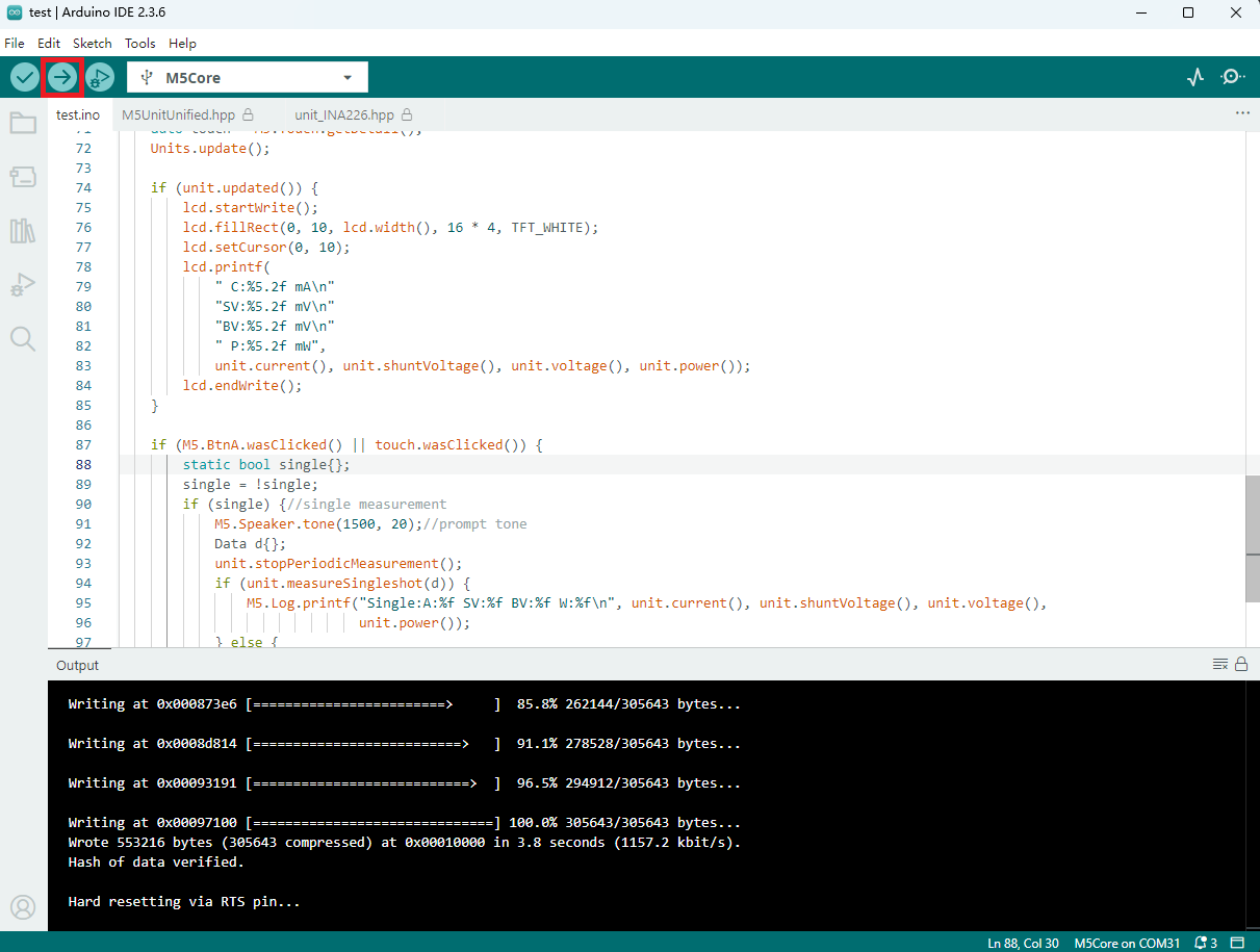
}4. Compile and Upload
- Select the device port (for details, please refer to Program Compilation and Upload), click the compile/upload button on the top left corner of Arduino IDE, and wait for the program to finish compiling and uploading to the device.
5. Voltage and Current Measurement Results
- The voltage, current, and other information of Unit Roller485 measured by Unit INA226-10A are shown in the image below.
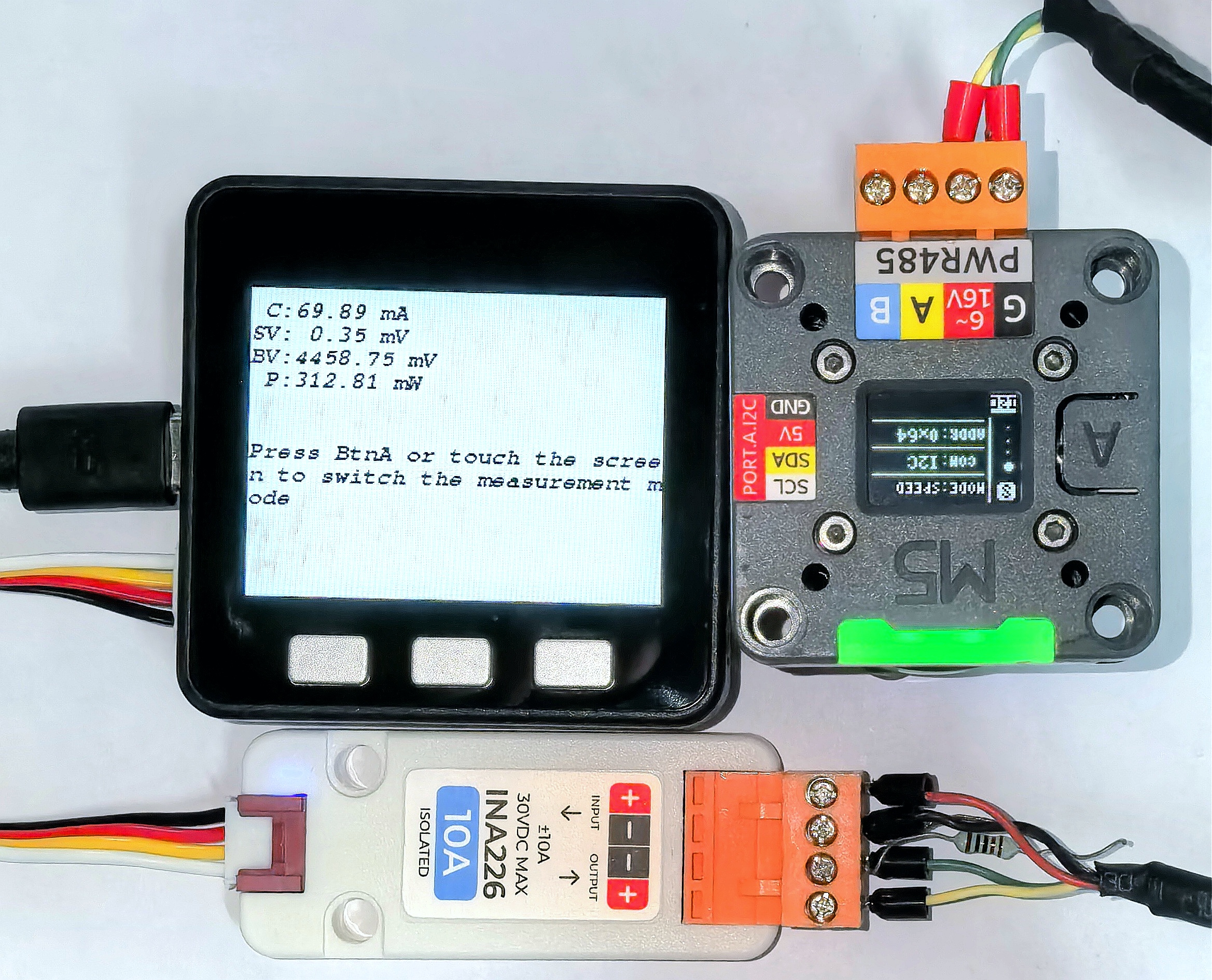
C represents current, SV represents shunt resistor voltage, BV represents bus voltage, P represents power; pressing button A or touching the screen (supported on host devices without physical buttons) can switch the measurement mode between single measurement and periodic measurement.