Arduino Quick Start
2. Devices & Examples
3. M5Unified
4. M5GFX
5. Extensions
Unit
Module
Atomic
Tab5
IoT
Accessories
PaperDIY Power Management
1. Multi-Level Power Switch Design
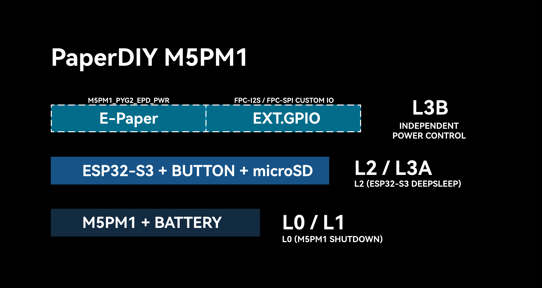
PaperDIY integrates the M5PM1 and its onboard power circuitry to implement multi-level power switching. Each power level controls the power supply for different peripherals and interfaces. You can enable only the levels required by your application and turn off unused peripherals to reduce overall power consumption.
M5PM1 Driver Library
The M5PM1 driver library can configure power outputs, GPIO, charging control, timers, and sleep functions.
L0
At this power level, the battery supplies the M5PM1 and the FPC-I2S interface, while the remaining peripherals can be powered off. As long as the battery is not depleted, this level remains active, and the M5PM1 supports power button power-on and power-off operations.
L1
At this power level, the device is in standby. The battery continues to supply the M5PM1, and the operations available at the L0 level remain supported.
L2 / L3A
This level additionally enables power for the ESP32-S3, microSD, user buttons, and FPC-SPI interface. The M5PM1 DCDC3V3_EN_PP controls the 3V3_L2 power switch. This is the operating power supply while the ESP32-S3 is running, and it can be controlled with the following API.
pm1.setDcdcEnable(true); // L2 ON
pm1.setDcdcEnable(false); // L2 OFF When the ESP32-S3 is sleeping, the power is at the L2 level. When the ESP32-S3 is running, the power is at the L3A level. The ESP32-S3 can put the M5PM1 into sleep and turn off its own power (L2 -> L1/L0).
L3B
This level controls the e-paper power, FPC control signals, and charging status. The M5PM1 GPIO connected to the FPC interface can be assigned custom functions. The M5PM1 API can control the e-paper power, charging, and other custom peripherals.
| M5PM1 | PYG0 | PYG1 | PYG2 | PYG3 | PYG4 |
|---|---|---|---|---|---|
| FPC - I2S | PY_G0 | ||||
| FPC - SPI | PY_G1 | PY_G4 | |||
| E-Paper | EPD_PWR | ||||
| Charge | CHG_STAT |
- PYG0(PY_G0): FPC-I2S interface expansion signal
- PYG1(PY_G1): FPC-SPI interface switch signal
- PYG2(EPD_PWR): E-paper panel and driver power enable
- PYG3(CHG_STAT): Charging status
- PYG4(PY_G4): FPC-SPI interface reset signal
M5PM1 PYG2 is connected to EPD_PWR and controls power for the e-paper panel and its driver circuit. The e-paper boost converter is enabled by ESP32-S3 GPIO46 (BST_EN). The screen can refresh normally only when both are enabled.
pm1.gpioSetFunc(M5PM1_GPIO_NUM_2, M5PM1_GPIO_FUNC_GPIO);
pm1.gpioSetMode(M5PM1_GPIO_NUM_2, M5PM1_GPIO_MODE_OUTPUT);
pm1.gpioSetDrive(M5PM1_GPIO_NUM_2, M5PM1_GPIO_DRIVE_PUSHPULL);
pm1.gpioSetOutput(M5PM1_GPIO_NUM_2, true); // EPD_PWR ONBattery Status
PaperDIY routes the battery voltage to the M5PM1 through BAT_ADC, which can be read with readVbat().
uint16_t batteryMv = 0;
if (pm1.readVbat(&batteryMv) == M5PM1_OK) {
    Serial.printf("VBAT: %u mV\n", batteryMv);
}Charging is enabled through CHG_EN. The charging status is read from CHG_STAT on PYG3, and a low level indicates that charging is in progress.
pm1.setChargeEnable(true);  // 开启充电

pm1.gpioSetFunc(M5PM1_GPIO_NUM_3, M5PM1_GPIO_FUNC_GPIO);
pm1.gpioSetMode(M5PM1_GPIO_NUM_3, M5PM1_GPIO_MODE_INPUT);
pm1.gpioSetPull(M5PM1_GPIO_NUM_3, M5PM1_GPIO_PULL_UP);

uint8_t chgStat = 1;
if (pm1.gpioGetInput(M5PM1_GPIO_NUM_3, &chgStat) == M5PM1_OK) {
    bool charging = (chgStat == 0);  // CHRG 低电平表示正在充电
}2. M5PM1 Sleep
Manual Sleep
The M5PM1 can enter sleep mode under program control to reduce overall power consumption. By default, calling shutdown() turns off 3V3_L2, stops the ESP32-S3, and keeps only the M5PM1's basic power management functions active.
pm1.shutdown();If an external circuit must remain powered during sleep, configure the required power hold conditions before calling shutdown(). Do not cut power to the PaperDIY e-paper display or FPC peripherals before their state has been saved.
I2C Idle Sleep
The M5PM1 can automatically enter low-power mode after the I2C bus has been idle for a configured period:
pm1.setI2cSleepTime(10); // I2C 空闲 10 秒后进入低功耗模式After entering this mode, the first communication between the ESP32-S3 and M5PM1 is used to wake the chip and may not complete a valid read or write. Read or write the target register in the next communication after wake-up.
3. M5PM1 Timer
The M5PM1 supports timers that can perform power-on, power-off, reset, or flag-setting actions when the countdown ends.
m5pm1_err_t timerSet(uint32_t seconds, m5pm1_tim_action_t action);typedef enum {
M5PM1_TIM_ACTION_STOP = 0b000, // 停止,无动作
// Stop, no action
M5PM1_TIM_ACTION_FLAG = 0b001, // 仅设置标志
// Set flag only
M5PM1_TIM_ACTION_REBOOT = 0b010, // 系统复位
// System reboot
M5PM1_TIM_ACTION_POWERON = 0b011, // 开机
// Power on
M5PM1_TIM_ACTION_POWEROFF = 0b100 // 关机
// Power off
} m5pm1_tim_action_t;Timed Power-On / Power-Off Example
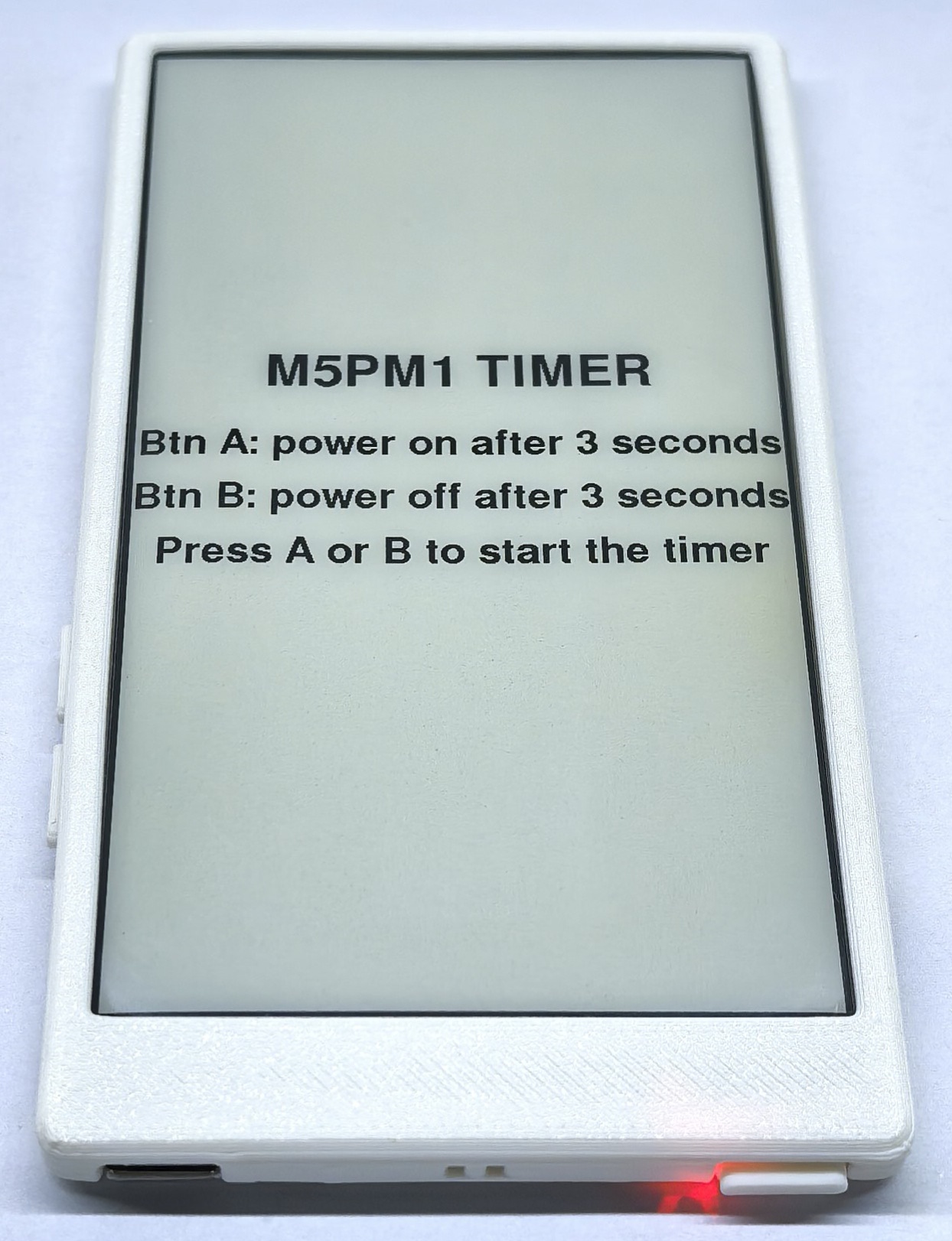
After the device starts, press BtnA to configure a power-on action after 3 seconds, or press BtnB to configure a power-off action after 3 seconds.
#include <M5Unified.h>
#include <M5PM1.h>

M5PM1 pm1;
bool pm1Ready = false;

static void drawMessage(const char* line1, const char* line2)
{
    M5.Display.clear();
    M5.Display.setTextDatum(middle_center);
    M5.Display.setFont(&fonts::FreeSansBold24pt7b);
    M5.Display.drawString(line1, M5.Display.width() / 2, M5.Display.height() / 2 - 30);
    M5.Display.setFont(&fonts::FreeSansBold18pt7b);
    M5.Display.drawString(line2, M5.Display.width() / 2, M5.Display.height() / 2 + 35);
}

static void drawTimerHome()
{
    M5.Display.clear();
    M5.Display.setTextDatum(middle_center);
    M5.Display.setFont(&fonts::FreeSansBold24pt7b);
    M5.Display.drawString("M5PM1 TIMER", M5.Display.width() / 2, M5.Display.height() / 2 - 110);
    M5.Display.setFont(&fonts::FreeSansBold18pt7b);
    M5.Display.drawString("Btn A: power on after 3 seconds", M5.Display.width() / 2, M5.Display.height() / 2 - 35);
    M5.Display.drawString("Btn B: power off after 3 seconds", M5.Display.width() / 2, M5.Display.height() / 2 + 20);
    M5.Display.drawString("Press A or B to start the timer", M5.Display.width() / 2, M5.Display.height() / 2 + 75);
}

void setup()
{
    auto cfg = M5.config();
    cfg.clear_display = false;
    M5.begin(cfg);
    Serial.begin(115200);

    M5.Display.setEpdMode(epd_mode_t::epd_text);
    const m5pm1_err_t err =
        pm1.begin(&M5.In_I2C, M5PM1_DEFAULT_ADDR, M5PM1_I2C_FREQ_100K);
    pm1Ready = (err == M5PM1_OK);

    if (!pm1Ready) {
        Serial.printf("M5PM1 init failed: %d\n", err);
        drawMessage("M5PM1 ERROR", "Check I2C");
        return;
    }

    Serial.println("BtnA: power on after 3s");
    Serial.println("BtnB: power off after 3s");
    drawTimerHome();
}

void loop()
{
    M5.update();
    if (!pm1Ready) {
        delay(1000);
        return;
    }

    if (M5.BtnA.wasPressed()) {
        drawMessage("Power OFF", "Power ON after 3s");
        delay(500);
        if (pm1.timerSet(3, M5PM1_TIM_ACTION_POWERON) == M5PM1_OK) {
            Serial.println("Power-on timer configured");
            pm1.shutdown();
        } else {
            Serial.println("Power-on timer configuration failed");
            drawMessage("Timer ERROR", "Power-on failed");
        }
    }

    if (M5.BtnB.wasPressed()) {
        drawMessage("Power OFF", "After 3 seconds");
        if (pm1.timerSet(3, M5PM1_TIM_ACTION_POWEROFF) == M5PM1_OK) {
            Serial.println("Power-off timer configured");
        } else {
            Serial.println("Power-off timer configuration failed");
            drawMessage("Timer ERROR", "Power-off failed");
        }
    }

    delay(20);
}