


Arduino 上手教程
2. 设备开发 & 案例程序
3. M5Unified
4. M5GFX
5. 拓展模块
Unit
Atomic
Base
Tab5
IoT
Unit INA226-1A/10A Arduino 使用教程
1. 准备工作
- 环境配置: 参考 Arduino IDE 上手教程完成 IDE 安装,并根据实际使用的开发板安装对应的板管理,与需要的驱动库。
- 使用到的驱动库:
注意
需要在 GitHub 上下载最新的库版本,库地址: M5Unit-METER - M5Stack GitHub,请勿在 Arduino Library 中下载。(如有疑问,请参考此教程)
- 使用到的硬件产品:
2. 注意事项
引脚兼容性
由于每款主机的引脚配置不同,为了让用户更方便地使用,M5Stack 官方提供了引脚兼容性表,方便用户查看,请根据实际引脚连接情况修改案例程序。
3. 案例程序
注意
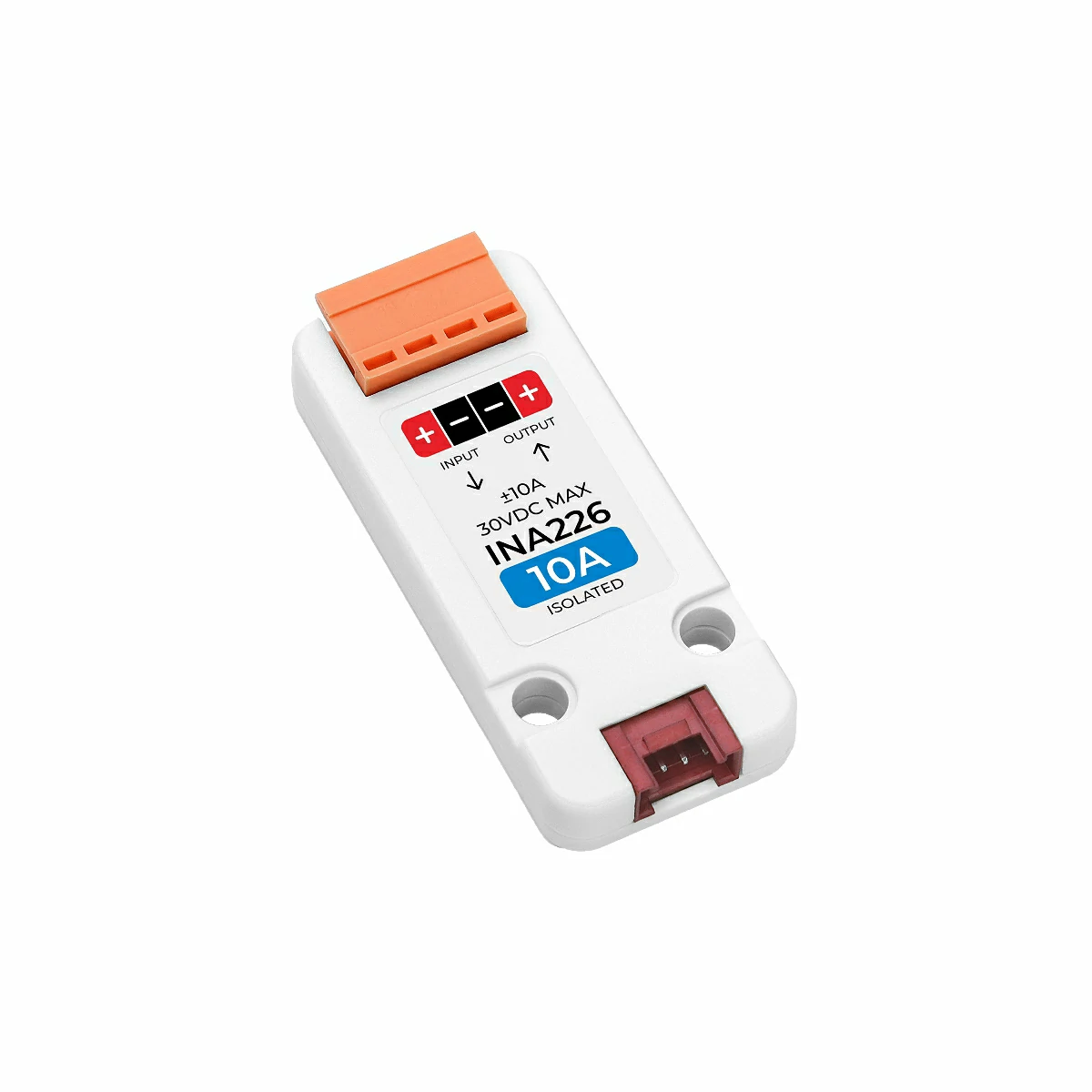
1. 请确保在使用本电流电压检测单元时,端口连接的电压正负极请严格按照单元上的贴纸所示,否则会损坏单元。INPUT 端具有自恢复保险丝,默认接入输入电源,OUTPUT 端接入负载(若反之,下方例程测量出的电流为负值)。
2. 输入电源可通过本单元向负载设备供电。
2. 输入电源可通过本单元向负载设备供电。
检测模式
- 1. 单次测量:单次测量当前电流、电压、功率等数据,使用
measureSingleshot函数设置。 - 2. 周期测量:周期性持续测量当前电流、电压、功率等数据,使用
startPeriodicMeasurement函数设置,stopPeriodicMeasurement函数停止。
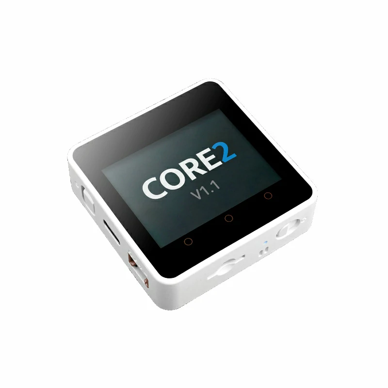
本教程中使用的主控设备为 Core2 v1.1 ,搭配 Unit INA226-10A(若搭配 Unit INA226-1A 请使用下方代码中的 #define USING_UNIT_INA226_1A)测量直流电机的电压及电流等。本电流电压检测单元采用 I2C 的方式通讯,根据实际的电路连接修改程序中的引脚定义,设备连接后对应的 I2C 引脚为 G33 (SCL),G32 (SDA)。
cpp
1 2 3 4 5 6 7 8 9 10 11 12 13 14 15 16 17 18 19 20 21 22 23 24 25 26 27 28 29 30 31 32 33 34 35 36 37 38 39 40 41 42 43 44 45 46 47 48 49 50 51 52 53 54 55 56 57 58 59 60 61 62 63 64 65 66 67 68 69 70 71 72 73 74 75 76 77 78 79 80 81 82 83 84 85 86 87 88 89 90 91 92 93 94 95 96 97 98 99 100
#include <M5Unified.h>
#include <M5UnitUnified.h>
#include <M5UnitUnifiedMETER.h>
#include <Wire.h>

// *************************************************************
// Choose one define symbol to match the unit you are using
// *************************************************************
#if !defined(USING_UNIT_INA226_1A) && !defined(USING_UNIT_INA226_10A)
// #define USING_UNIT_INA226_1A
#define USING_UNIT_INA226_10A
#endif

namespace {
auto& lcd = M5.Display;
m5::unit::UnitUnified Units;
#if defined(USING_UNIT_INA226_1A)
#pragma message "Using 1A"
m5::unit::UnitINA226_1A unit_ina226;
#elif defined(USING_UNIT_INA226_10A)
#pragma message "Using 10A"
m5::unit::UnitINA226_10A unit_ina226;
#else
#error "Choose unit"
#endif
}  // namespace

void setup()
{
    M5.begin();

    // The screen shall be in landscape mode
    if (lcd.height() > lcd.width()) {
        lcd.setRotation(1);
    }

    auto pin_num_sda = M5.getPin(m5::pin_name_t::port_a_sda);
    auto pin_num_scl = M5.getPin(m5::pin_name_t::port_a_scl);
    M5_LOGI("getPin: SDA:%u SCL:%u", pin_num_sda, pin_num_scl);

    Wire.end();
    Wire.begin(pin_num_sda, pin_num_scl, 400000U);
    if (!Units.add(unit_ina226, Wire) || !Units.begin()) {
        M5_LOGE("Failed to begin");
        lcd.clear(TFT_RED);
        while (true) {
            m5::utility::delay(10000);
        }
    }
    lcd.setFont(&fonts::FreeMonoBoldOblique9pt7b);
    lcd.setTextColor(TFT_BLACK);

    M5_LOGI("M5UnitUnified has been begun");
    M5_LOGI("%s", Units.debugInfo().c_str());
    lcd.clear(TFT_WHITE);
    lcd.setCursor(0, 120);
    lcd.printf("Press BtnA or touch the screen to switch the measurement mode");
}

void loop()
{
    using namespace m5::unit::ina226;

    M5.update();
    auto touch = M5.Touch.getDetail();
    Units.update();

    if (unit_ina226.updated()) {
        lcd.startWrite();
        lcd.fillRect(0, 10, lcd.width(), 24 * 4, TFT_WHITE);
        lcd.setCursor(0, 10);
        lcd.printf(
            " C:%5.2f mA\n"
            "SV:%5.2f mV\n"
            "BV:%5.2f mV\n"
            " P:%5.2f mW",
            unit_ina226.current(), unit_ina226.shuntVoltage(), unit_ina226.voltage(), unit_ina226.power());
        lcd.endWrite();
    }

    if (M5.BtnA.wasClicked() || touch.wasClicked()) {//switch measurement mode
        static bool single{};
        single = !single;
        if (single) {//single measurement
            M5.Speaker.tone(1500, 20);//prompt tone
            Data d{};
            unit_ina226.stopPeriodicMeasurement();
            if (unit_ina226.measureSingleshot(d)) {
                M5.Log.printf("Single:A:%f SV:%f BV:%f W:%f\n", unit_ina226.current(), unit_ina226.shuntVoltage(), unit_ina226.voltage(),
                              unit_ina226.power());
            } else {
                M5_LOGE("Failed to measureSingleshot");
            }
        } else {//periodic measurement
            M5.Speaker.tone(2500, 20);//prompt tone
            M5.Log.printf("Start periodic\n");
            unit_ina226.startPeriodicMeasurement();
        }
    }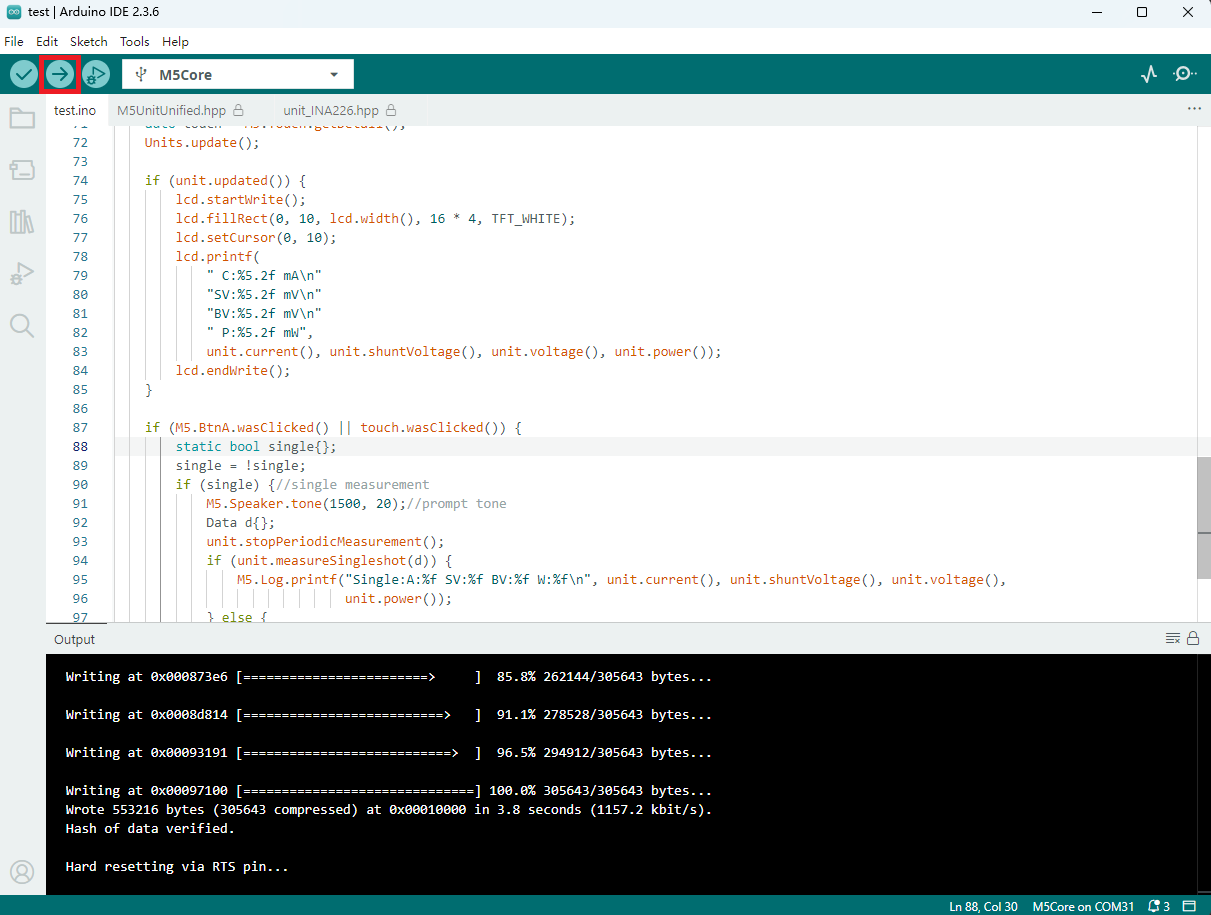
}4. 编译上传
- 选中设备端口(详情请参考 程序编译与烧录),点击 Arduino IDE 左上角编译上传按钮,等待程序完成编译并上传至设备。
5. 电压电流测量结果
- Unit INA226-10A 测量的直流电机电压电流等信息如下图中所示。
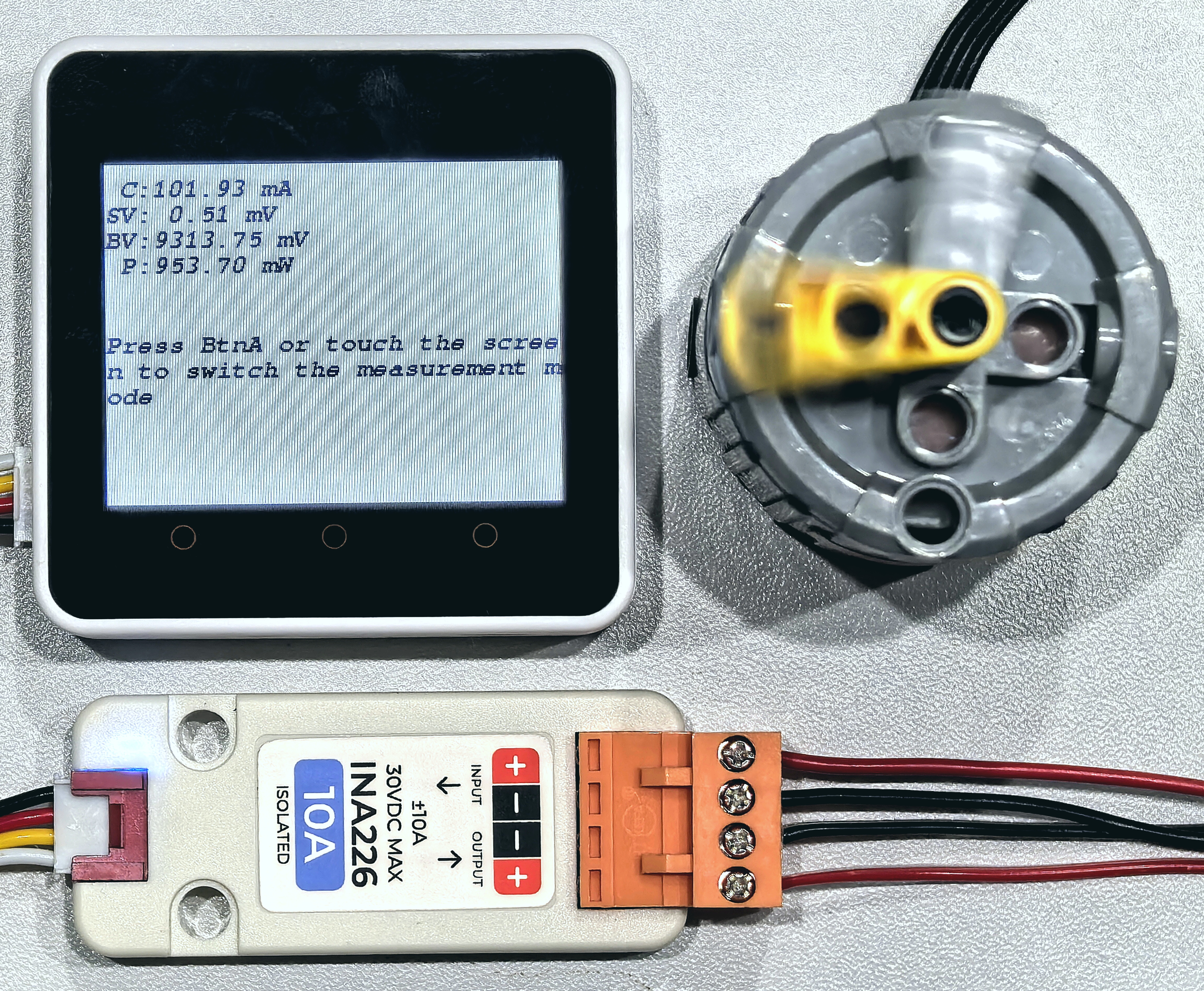
其中 C 表示电流,SV 表示分流电阻电压,BV 表示总线电压,P 表示功率;按动按键 A 或触摸屏幕(支持无实体按键主控设备)可切换测量模式为单次测量或周期测量。