


Arduino Quick Start
2. Devices & Examples
3. M5Unified
4. M5GFX
5. Extensions
Unit
Atomic
Tab5
IoT
Accessories
Atomic Stepmotor Base Arduino Tutorial
1. Preparation
Environment setup: Refer to Arduino IDE Getting Started Tutorial to complete the IDE installation, and install the corresponding board manager and required driver libraries according to the actual development board used.
Required driver libraries:
Hardware used:
2. Basics of Stepper Motor Control
A stepper motor converts electrical pulses into discrete angular movements. Each pulse advances the motor shaft by a fixed angle. Because of this behavior, stepper motors are well suited for applications that require precise position control such as 3D printers, CNC machines and robotics.
1. Structure:
- Stator: made up of multiple windings that create magnetic fields when energized.
- Rotor: typically a toothed iron core that reacts to the stator's magnetic field and rotates.
2. Working principle:
- By energizing the A and B phase windings in a specific sequence, a rotating magnetic field is produced and the rotor follows. One control pulse switches the winding state and advances the rotor by one step. Pulse frequency controls speed; the number of pulses determines the total angular displacement.
3. Key parameters:
- Phases: number of winding phases (common types are 2-phase, 3-phase, 4-phase, 5-phase).
- Number of full steps: base number of steps per revolution determined by the motor's construction. A typical 2‑phase motor uses 200 steps/rev (i.e., 200 full-step pulses = 360°).
- Step angle: the rotation angle per full step. Step angle = 360° / number_of_full_steps. For a 200-step motor this equals 1.8°.
- Microstepping: dividing a full step into smaller steps by controlling coil currents; this improves positioning resolution and smoothness. Common subdivisions are 1/2, 1/4, 1/8, 1/16, etc.
- Speed: typically given in RPM. Speed depends on pulse frequency and load. RPM = (pulse_frequency / number_of_full_steps) × 60.
- Holding torque: maximum torque the motor can resist while stationary. Typical 2‑phase motors range from 0.1 to 5 N·m depending on the model.
3. Example
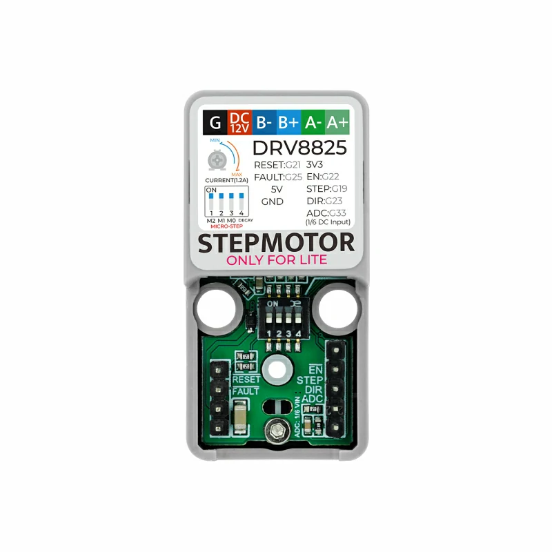
- This example uses an AtomS3R paired with the Atomic Stepmotor Base. The driver is controlled using step/dir/enable signals. Adjust the pin definitions below to match your wiring. On the AtomS3R the example uses
G5 (EN),G6 (STEP), andG7 (DIR).
3.1 DIP switch (microstep) settings
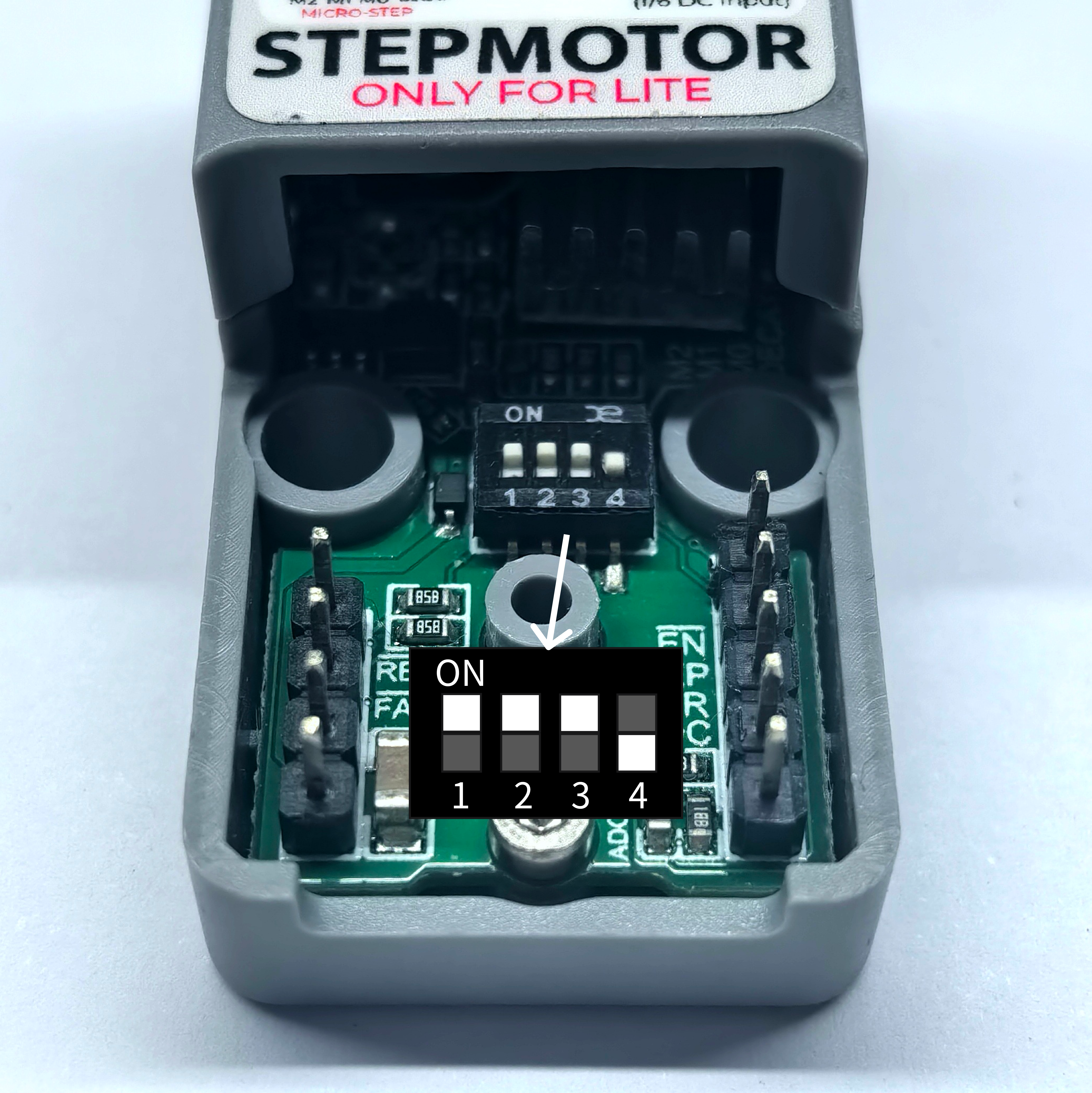
The Atomic Stepmotor Base provides a DIP switch for selecting microstepping. The four switches M2, M1, M0 and DECAY correspond to the DRV8825 pins MODE2, MODE1, MODE0 and DECAY. M2/M1/M0 select the microstep mode; DECAY selects current decay behavior. See the DRV8825 datasheet for details.
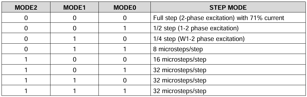
In the sketch below, change the step_division variable to match the DIP switch microstepping setting. The example images use 1/32 microstepping.
3.2 Example code
#include "M5Unified.h"
#include "M5GFX.h"

// Stepper motor configuration parameters
int step_division = 32;           // Motor microstepping division factor
int number_of_steps = 200;       // Number of steps per full revolution of the motor
int en_pin = 5;                  // Motor driver enable pin
int step_pin = 6;                // Motor step control pin
int dir_pin = 7;                 // Motor direction control pin

// Timing variables for step control
unsigned long step_interval = 10000;  // Microsecond interval between step pulses
unsigned long last_step_time = 0;     // Timestamp of the last step pulse
unsigned long target_step_time1 = 0;  // Target time for step pin HIGH state
unsigned long target_step_time2 = 0;  // Target time for step pin LOW state

void motor_setSpeed(float rpm);               // Set motor rotation speed (revolutions per minute)
void motor_powerEnable(bool ena);             // Enable/disable motor driver
void motor_setDirection(long steps_to_move);  // Set rotation direction based on step count
void motor_move();                            // Generate a single step pulse
void motor_moveInterval(unsigned long target_delay);  // Control step pulse timing
void motor_dynamicMove(int s1, int s2);       // Step with dynamic acceleration/deceleration
void motor_step(long steps_to_move);          // Move specified steps without acceleration
void motor_step_accdec(long steps_to_move, long steps_acc, long steps_dec);  // Move with acceleration/deceleration

void setup() {
  M5.begin();
  M5.Lcd.setFont(&fonts::FreeMonoBoldOblique9pt7b);  // Set display font
  M5.Lcd.drawCenterString("Motor", 64, 64);          // Display title at center

  pinMode(en_pin, OUTPUT);
  pinMode(dir_pin, OUTPUT);
  pinMode(step_pin, OUTPUT);

  motor_setSpeed(0);       // Set initial speed to 0
  motor_powerEnable(true); // Enable motor driver
  delay(1600);             // Short delay for initialization
}

void loop() {
  M5.update();

  if (M5.BtnA.wasPressed()) {
    motor_setSpeed(300);   // Set motor speed to 300 RPM
    motor_step(1200);      // Rotate 1200 steps clockwise
    motor_step(-1200);     // Rotate 1200 steps counter-clockwise
  }
}

// ---- Function Definitions ----

/**
 * Set motor rotation speed in revolutions per minute (RPM)
 * Calculates step interval based on RPM, steps per revolution, and microstepping
 * @param rpm Target rotation speed in revolutions per minute
 */
void motor_setSpeed(float rpm) {
  // Calculate microsecond interval between steps:
  // 60,000,000 microseconds/minute ÷ (steps/rev × RPM × microsteps)
  step_interval = 60000000L / (number_of_steps * rpm * step_division);
}

/**
 * Enable or disable the motor driver
 * @param ena True to enable motor (driver active), false to disable
 */
void motor_powerEnable(bool ena) {
  digitalWrite(en_pin, ena ? LOW : HIGH);  // Typically, LOW enables most drivers
}

/**
 * Set motor rotation direction based on step count sign
 * @param steps_to_move Positive for clockwise, negative for counter-clockwise
 */
void motor_setDirection(long steps_to_move) {
  if (steps_to_move < 0) {
    digitalWrite(dir_pin, HIGH);  // Set direction pin for counter-clockwise
  } else {
    digitalWrite(dir_pin, LOW);   // Set direction pin for clockwise
  }
}

/**
 * Generate a single step pulse (HIGH then LOW) with proper timing
 */
void motor_move() {
  digitalWrite(step_pin, HIGH);    // Set step pin HIGH to trigger step
  motor_moveInterval(step_interval);  // Maintain HIGH state and then transition to LOW
}

/**
 * Control timing for step pin state transitions
 * Ensures proper duration for HIGH and LOW states of the step pulse
 * @param target_delay Total duration of one step cycle (HIGH + LOW) in microseconds
 */
void motor_moveInterval(unsigned long target_delay) {
  // Calculate target times for state transitions
  target_step_time1 = last_step_time + (target_delay / 2);  // Midpoint (HIGH to LOW)
  target_step_time2 = last_step_time + target_delay;        // End of cycle (LOW to next step)

  // Wait for HIGH state duration
  if (target_step_time1 >= last_step_time) {
    while (micros() < target_step_time1) {}  // Handle normal time progression
  } else {
    while ((long)(micros()) < (long)target_step_time1) {}  // Handle micros() rollover
  }

  digitalWrite(step_pin, LOW);  // Set step pin LOW after half the interval

  // Wait for remaining LOW state duration
  if (target_step_time2 >= last_step_time) {
    while (micros() < target_step_time2) {}  // Handle normal time progression
  } else {
    while ((long)(micros()) < (long)target_step_time2) {}  // Handle micros() rollover
  }

  last_step_time = micros();  // Update last step timestamp
}

/**
 * Generate a step with dynamic speed adjustment for acceleration/deceleration
 * @param s1 Current step in acceleration/deceleration phase
 * @param s2 Total steps in acceleration/deceleration phase
 */
void motor_dynamicMove(int s1, int s2) {
  digitalWrite(step_pin, HIGH);  // Start step pulse

  // Calculate speed ratio using polynomial for smooth acceleration/deceleration
  double r1 = (double)s1 / (double)s2;
  double r2 = 0.1 + 0.2*r1 + 2.2*r1*r1 - 1.5*r1*r1*r1;

  // Adjust step interval based on calculated ratio
  motor_moveInterval((unsigned long)(step_interval / r2));
}

/**
 * Move motor specified number of steps without acceleration
 * Converts input steps to microstepped steps using step_division
 * @param steps_to_move Number of steps to move (positive = clockwise, negative = counter-clockwise)
 */
void motor_step(long steps_to_move) {
  steps_to_move *= step_division;  // Convert to microstepped steps
  motor_setDirection(steps_to_move);  // Set rotation direction
  last_step_time = micros();        // Initialize step timestamp

  // Generate each step pulse
  for (long i = abs(steps_to_move); i > 0; i--) {
    motor_move();
  }
}

/**
 * Move motor with acceleration, constant speed, and deceleration phases
 * @param steps_to_move Total steps to move (signed for direction)
 * @param steps_acc Number of steps used for acceleration phase
 * @param steps_dec Number of steps used for deceleration phase
 */
void motor_step_accdec(long steps_to_move, long steps_acc, long steps_dec) {
  // Convert all step counts to microstepped values
  steps_to_move *= step_division;
  steps_acc *= step_division;
  steps_dec *= step_division;

  motor_setDirection(steps_to_move);  // Set rotation direction
  last_step_time = micros();          // Initialize step timestamp

  // Acceleration phase: gradually increase speed
  if (steps_acc > 0) {
    for (long i = 1; i <= steps_acc; i++) {
      motor_dynamicMove(i, steps_acc);
    }
  }

  // Constant speed phase: maintain steady speed
  long constant_steps = abs(steps_to_move) - abs(steps_acc) - abs(steps_dec);
  for (long i = constant_steps; i > 0; i--) {
    motor_move();
  }

  // Deceleration phase: gradually decrease speed
  if (steps_dec > 0) {
    for (long i = (steps_dec - 1); i >= 0; i--) {
      motor_dynamicMove(i, steps_dec);
    }
  }
}4. Compile and Upload
- 1. Download Mode: Before flashing programs to different devices, download mode is required. This step may vary depending on the main control device used. For details, refer to the device program download tutorial list at the bottom of the Arduino IDE Getting Started Tutorial page to view the specific operation method.
- For AtomS3R, press and hold the reset button (for about 2 seconds) until the internal green LED lights up, then release. At this point, the device has entered download mode and is ready for flashing.
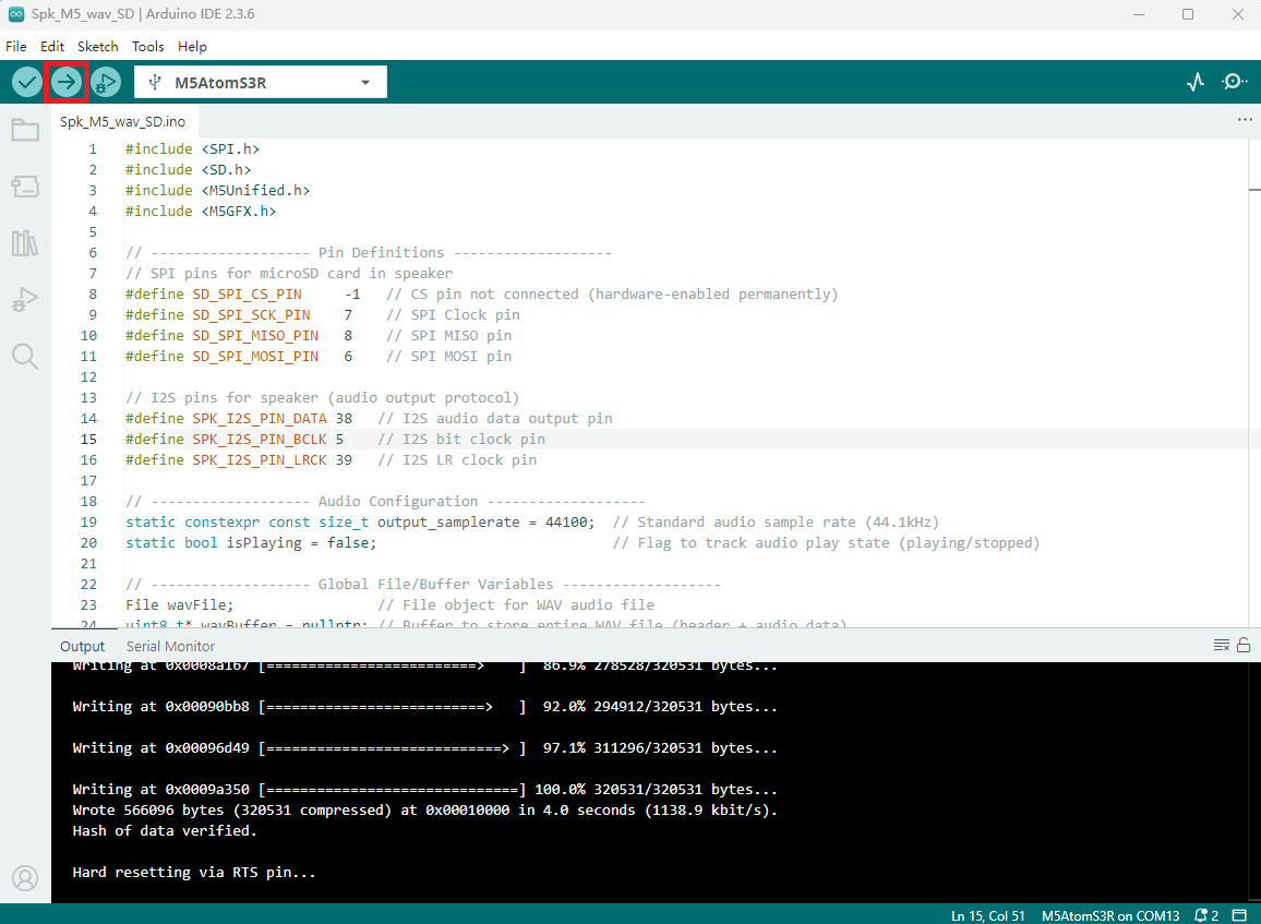
- 2. Select the device port, click the compile/upload button in the upper left corner of the Arduino IDE, and wait for the program to finish compiling and uploading to the device.
5. Stepping Motor Operation
- After powering the device, tap the screen once. The stepper motor will rotate forward for 6 turns (1200 steps) and then reverse for 6 turns (1200 steps). See the demonstration below.