


Arduino 上手教程
2. 设备开发 & 案例程序
3. M5Unified
4. M5GFX
5. 拓展模块
Unit
Atomic
Tab5
IoT
Atomic PWM Base Arduino 使用教程
1. 准备工作
环境配置: 参考 Arduino IDE 上手教程完成 IDE 安装,并根据实际使用的开发板安装对应的板管理,与需要的驱动库。
使用到的驱动库:
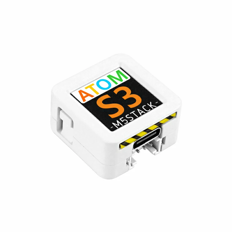
使用到的硬件产品:

2. 案例程序
- 本教程中使用的主控设备为 AtomS3 ,搭配 Atomic PWM Base,PWM 信号输出引脚为
G5(SIGNAL)。
cpp
1 2 3 4 5 6 7 8 9 10 11 12 13 14 15 16 17 18 19 20 21 22 23 24 25 26 27 28 29
#include "M5Unified.h"

#define SIGNAL 5 // PWM signal output pin

int freq        = 10000; // 10kHz
int resolution  = 10;    // Duty cycle resolution in bits (10-bit = 0 to 1023)

void setup() {
    M5.begin();

    M5.Display.setTextColor(GREEN);
    M5.Display.setTextDatum(middle_center);
    M5.Display.setFont(&fonts::Orbitron_Light_24);
    M5.Display.drawString("PWM", M5.Display.width() / 2, M5.Display.height() / 2);

    ledcAttach(SIGNAL, freq, resolution);// Bind the pin, frequency, and resolution
}

void loop() {
    for (int i = 0; i < 500; i++) {
        ledcWrite(SIGNAL, i);// Update the PWM duty cycle
        delay(2);
    }

    for (int i = 500; i > 0; i--) {
        ledcWrite(SIGNAL, i);
        delay(2);
    }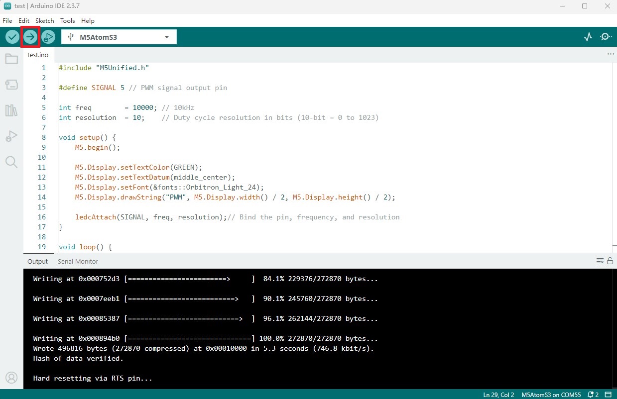
}3. 编译上传
- 1. AtomS3 长按复位按键 (大约 2 秒) 直到内部绿色 LED 灯亮起,便可松开,此时设备已进入下载模式,等待烧录。
说明
不同设备进行程序烧录前需要进入下载模式,不同的主控设备该步骤可能有所不同。详情可参考Arduino IDE上手教程页面底部的设备程序下载教程列表,查看具体的操作方式。
- 2. 选中设备端口,点击 Arduino IDE 左上角编译上传按钮,等待程序完成编译并上传至设备。
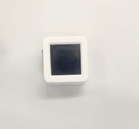
4. PWM 信号输出控制灯带亮度
- 设备上电后会开始输出 PWM 信号,此时灯带会逐渐变亮,然后逐渐变暗,循环往复。