Arduino Quick Start
2. Devices & Examples
3. M5Unified
4. M5GFX
5. Extensions
Unit
Atomic
Tab5
IoT
Accessories
Voice Pyramid Arduino Tutorial
1. Preparation
Environment setup: Refer to Arduino IDE Quick Start to complete IDE installation, and install the corresponding board package for the development board in use along with the required driver libraries.
Required libraries:
Required hardware products:

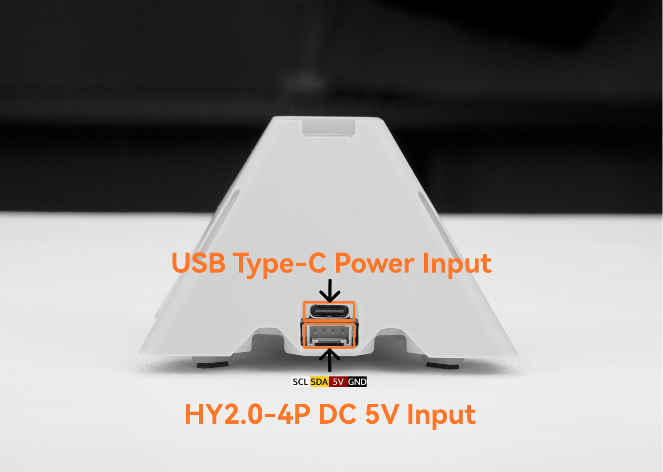
This tutorial demonstrates how to use the AtomS3R together with the Voice Pyramid. Pin pairing can be referenced in the compatibility diagram below.
2. Voice Pyramid Communication Overview
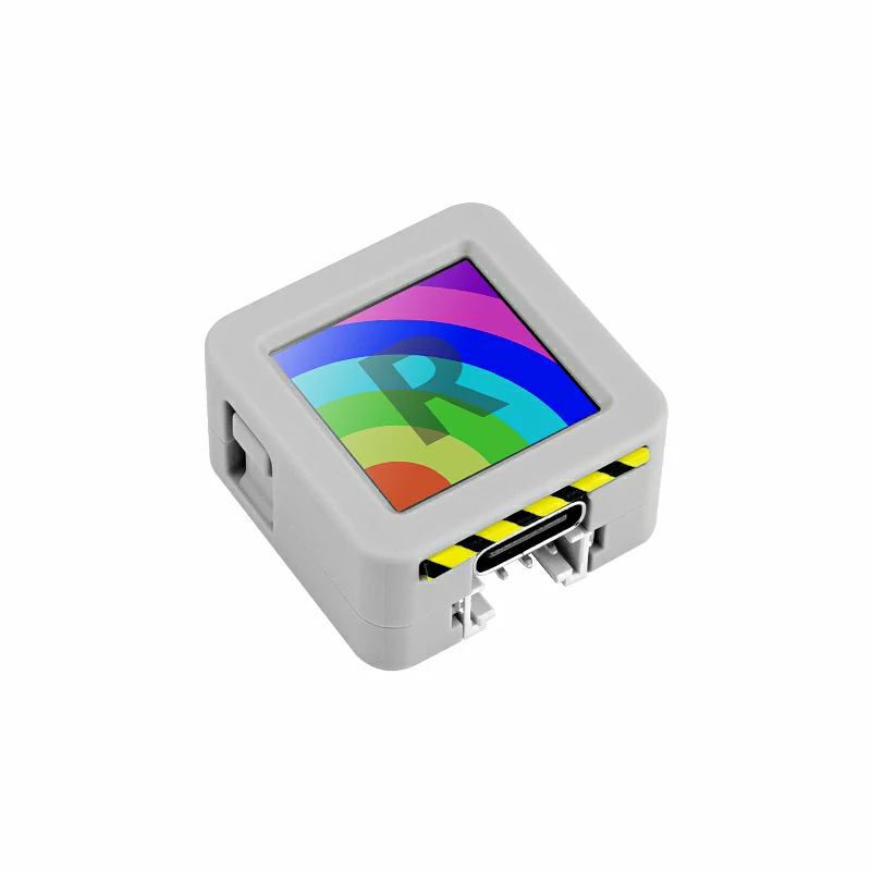
Voice Pyramid is a professional development base designed for smart voice applications, specifically built for the M5Stack Atom series controllers. By vertically inserting an Atom controller into the reserved header pins, developers can quickly build voice-enabled devices with powerful audio interaction capabilities. The ATOM module (based on ESP32 or ESP32-S3) serves as the main controller, handling audio processing, wireless communication (Wi-Fi/Bluetooth), and IoT connectivity, making it suitable for various voice interaction scenarios such as voice assistants, smart control hubs, and IoT voice terminals.
The device features a high-quality audio system with an ES8388 audio codec and an ES7210 dual-microphone front-end with MEMS microphones for clear voice capture and noise suppression. A built-in 2W speaker powered by the AW87559 Class-D amplifier provides powerful audio output. For interaction, an STM32G030F6P6 microcontroller manages capacitive touch inputs and RGB LEDs, offering responsive touch control and dynamic visual feedback. The system also integrates a Si5351 programmable clock generator to ensure stable audio performance for voice applications.
Touch:Four capacitive touch pads enable intuitive user interaction and quick control of device functions.Microphone:Dual MEMS microphones support clear voice capture and are suitable for voice recognition and voice command applications.RGB LED:Integrated programmable RGB LEDs provide visual feedback, status indication, and dynamic lighting effects.Speaker:A built-in 2W speaker delivers clear audio playback for voice responses, notifications, and multimedia output.
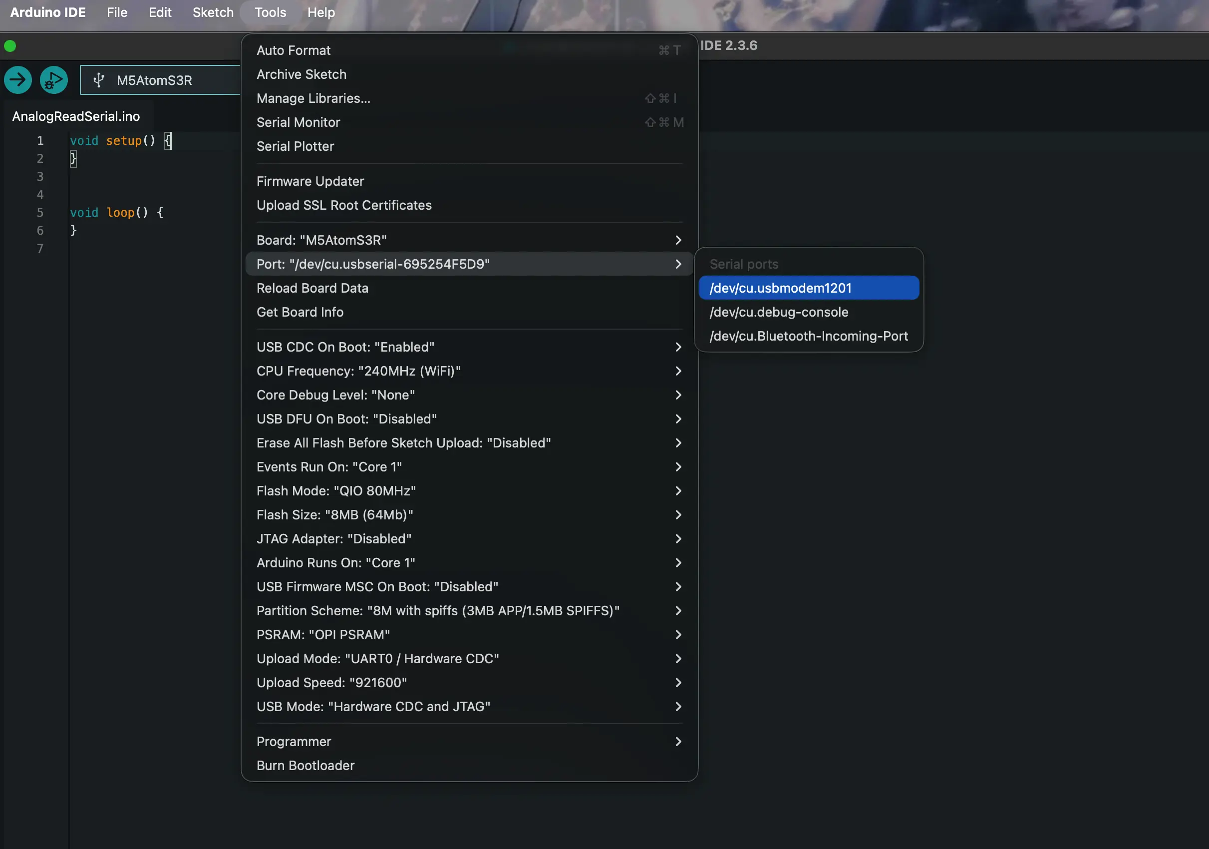
3. Port Selection
Press and hold the button on the right side of the AtomS3R, then connect the USB cable to the device.
4. Example Program
The following examples demonstrate the core hardware features and basic usage of the Voice Pyramid. These examples cover RGB LED control, audio recording and playback, touch interaction, and microphone audio capture, helping users quickly understand how to interact with the device and access its main peripherals through simple Arduino programs. By uploading these example programs, developers can learn how to control the RGB LEDs, detect touch input, record and play audio through the microphone and speaker, and monitor device status through the Serial Monitor.
RGB LED
#include "M5Unified.h"
#include <M5EchoPyramid.h>

M5EchoPyramid ep;

int brightness = 0;
int step = 5;
bool rising = true;

int leds[4] = {0, 3, 7, 10};

void setup()
{
    M5.begin();
    Serial.begin(115200);

    Wire1.end();
    ep.begin(&Wire1, 38, 39, 6, 8, 5, 7, 44100);

    ep.ctrl().setBrightness(1, 100);
    ep.ctrl().setBrightness(2, 100);

    Serial.println("LED demo start");
}

void loop()
{
    if (rising)
    {
        brightness += step;
        if (brightness >= 255)
        {
            brightness = 255;
            rising = false;
        }
    }
    else
    {
        brightness -= step;
        if (brightness <= 10)
        {
            brightness = 10;
            rising = true;
        }
    }
    for (int i = 0; i < 4; i++)
    {
        ep.ctrl().setRGB(1, leds[i], brightness, 0, 255 - brightness);
        ep.ctrl().setRGB(2, leds[i], brightness, 0, 255 - brightness);
    }

    delay(40);
}Copy the program above into Arduino IDE, click the Upload button, and wait until the compilation and upload process are completed. After the program starts running on the device, four LEDs on the Voice Pyramid (positions 0, 3, 7, and 10) on both LED rings will begin displaying a smooth breathing color effect. The LED brightness will gradually increase and decrease, while the color transitions between red and blue, creating a purple gradient during the transition. This animation loops continuously, demonstrating how to control the RGB LEDs on the Voice Pyramid.
Speaker
#include "M5Unified.h"
#include <M5EchoPyramid.h>

#define SAMPLE_RATE 44100
#define RECORD_SECONDS 5
#define FRAME_SIZE 256
#define TOTAL_SAMPLES (SAMPLE_RATE * RECORD_SECONDS)

M5EchoPyramid ep;

int16_t *recordBuffer = nullptr;
bool recordingBusy = false;

void recordAndPlay5s()
{
    if (recordingBusy) return;
    recordingBusy = true;

    Serial.println("Start 5s Recording...");

    int16_t mic[FRAME_SIZE];
    int16_t ref[FRAME_SIZE];
    int written = 0;

    while (written < TOTAL_SAMPLES) {
        ep.read(mic, ref, FRAME_SIZE);
        memcpy(recordBuffer + written, mic, FRAME_SIZE * sizeof(int16_t));
        written += FRAME_SIZE;
    }

    Serial.println("Recording Done.");
    delay(200);

    Serial.println("Start Playback...");

    int played = 0;
    while (played < TOTAL_SAMPLES) {
        ep.write(recordBuffer + played, FRAME_SIZE);
        played += FRAME_SIZE;
    }

    Serial.println("Playback Done.");

    recordingBusy = false;
}

void setup()
{
    M5.begin();
    Serial.begin(115200);
    delay(2000);

    Wire1.end();
    ep.begin(&Wire1, 38, 39, 6, 8, 5, 7, SAMPLE_RATE);

    ep.codec().setVolume(50);
    ep.codec().mute(false);

    recordBuffer = (int16_t *)malloc(TOTAL_SAMPLES * sizeof(int16_t));
    if (!recordBuffer) {
        Serial.println("Memory allocation failed!");
        while (1) {
            delay(1000);
        }
    }

    Serial.println("System Ready. Press touch1 to record & play 5s audio.");
}

void loop()
{
    if (ep.ctrl().isPressed(1)) {
        recordAndPlay5s();

        while (ep.ctrl().isPressed(1)) {
            delay(10);
        }
    }

    delay(10);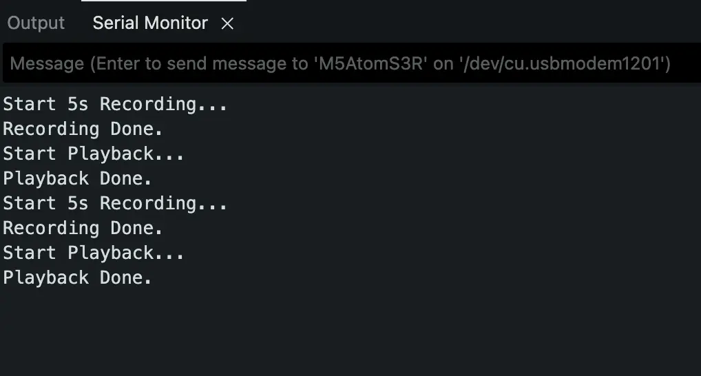
}Copy the program above into Arduino IDE, click the Upload button, and wait until the compilation and upload process are completed. After the device starts running, press Touch Button 1 on the Voice Pyramid to begin recording. The device will capture 5 seconds of audio from the built-in microphone and store the raw PCM data in memory. Once the recording is finished, the device will automatically play back the recorded audio through the speaker. Messages such as “Start 5s Recording…”, “Recording Done.”, “Start Playback…”, and “Playback Done.” will be displayed in the Serial Monitor, demonstrating how to record and immediately play back audio using the Voice Pyramid.
Touch
#include "M5Unified.h"
#include <M5EchoPyramid.h>

#define INITIAL_BRIGHTNESS 50
#define INITIAL_VOLUME     50
#define STEP               5

M5EchoPyramid ep;

int brightnessLevel = INITIAL_BRIGHTNESS;
int volumeLevel     = INITIAL_VOLUME;

bool brightnessGestureActive = false;
bool volumeGestureActive     = false;

void applyBrightness()
{
    ep.ctrl().setBrightness(1, brightnessLevel);
    ep.ctrl().setBrightness(2, brightnessLevel);
}

void fillLedsColor(uint8_t r, uint8_t g, uint8_t b)
{
    for (int i = 0; i < 14; ++i) {
        ep.ctrl().setRGB(1, i, r, g, b);
        ep.ctrl().setRGB(2, i, r, g, b);
    }
}

void applyVolume()
{
    ep.codec().setVolume(volumeLevel);
}

void setup()
{
    M5.begin();
    Serial.begin(115200);
    delay(2000);

    Wire1.end();
    ep.begin(&Wire1, 38, 39, 6, 8, 5, 7, 44100);
    ep.codec().mute(false);

    fillLedsColor(255, 255, 255);
    applyBrightness();
    applyVolume();
}

void loop()
{
    bool t1 = ep.ctrl().isPressed(1);
    bool t2 = ep.ctrl().isPressed(2);
    bool t3 = ep.ctrl().isPressed(3);
    bool t4 = ep.ctrl().isPressed(4);

    if (!brightnessGestureActive) {
        if (t1 && !t2) {
            brightnessGestureActive = true;
            brightnessLevel += STEP;
            if (brightnessLevel > 100) brightnessLevel = 100;
            applyBrightness();
            Serial.printf("Brightness: %d%%\n", brightnessLevel);
        } else if (t2 && !t1) {
            brightnessGestureActive = true;
            brightnessLevel -= STEP;
            if (brightnessLevel < 0) brightnessLevel = 0;
            applyBrightness();
            Serial.printf("Brightness: %d%%\n", brightnessLevel);
        }
    } else {
        if (!t1 && !t2) {
            brightnessGestureActive = false;
        }
    }

    if (!volumeGestureActive) {
        if (t4 && !t3) {
            volumeGestureActive = true;
            volumeLevel += STEP;
            if (volumeLevel > 100) volumeLevel = 100;
            applyVolume();
            Serial.printf("Volume: %d%%\n", volumeLevel);
        } else if (t3 && !t4) {
            volumeGestureActive = true;
            volumeLevel -= STEP;
            if (volumeLevel < 0) volumeLevel = 0;
            applyVolume();
            Serial.printf("Volume: %d%%\n", volumeLevel);
        }
    } else {
        if (!t3 && !t4) {
            volumeGestureActive = false;
        }
    }

    delay(10);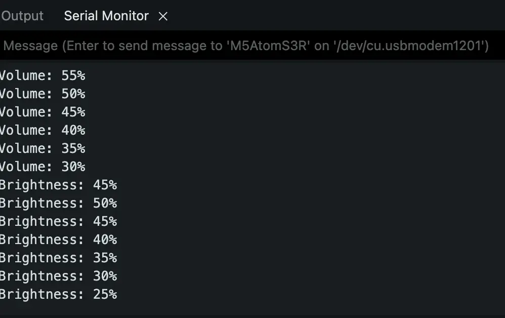
}Copy the program above into Arduino IDE, click the Upload button, and wait until the compilation and upload process are complete. After the firmware is running on the Voice Pyramid, the four touch pads can be used to control LED brightness and speaker volume.
Touch1 ~ Touch2:
These two touch pads control the LED brightness of the device.
- Touch1: Increase brightness by 5% each press.
- Touch2: Decrease brightness by 5% each press. The brightness value ranges from 0% to 100%, and the updated value will be printed in the Serial Monitor.
Touch3 ~ Touch4:
These two touch pads control the speaker volume.
- Touch4: Increase volume by 5% each press.
- Touch3: Decrease volume by 5% each press. The volume level also ranges from 0% to 100%, and the current value will be displayed in the Serial Monitor.
Microphone
#include "M5Unified.h"
#include <M5EchoPyramid.h>
#define SAMPLE_RATE 44100
#define RECORD_SECONDS 5
#define FRAME_SIZE 256
#define TOTAL_SAMPLES (SAMPLE_RATE * RECORD_SECONDS)
M5EchoPyramid ep;
int16_t *recordBuffer = nullptr;
bool recordingBusy = false;
void record5s()
{
if (recordingBusy) return;
recordingBusy = true;
Serial.println("Start 5s Recording...");
int16_t mic[FRAME_SIZE];
int16_t ref[FRAME_SIZE];
int written = 0;
while (written < TOTAL_SAMPLES) {
ep.read(mic, ref, FRAME_SIZE);
memcpy(recordBuffer + written, mic, FRAME_SIZE * sizeof(int16_t));
written += FRAME_SIZE;
}
Serial.println("Recording Done.");
const int channels = 1;
const int bitsPerSample = 16;
const int totalSamples = TOTAL_SAMPLES;
const size_t totalBytes = totalSamples * sizeof(int16_t);
const float durationSeconds = (float)totalSamples / SAMPLE_RATE;
const int totalFrames = totalSamples / FRAME_SIZE;
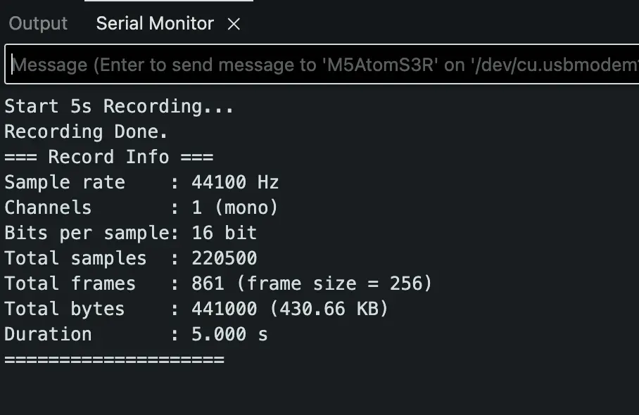
Serial.println("=== Record Info ===");
Serial.printf("Sample rate : %d Hz\n", SAMPLE_RATE);
Serial.printf("Channels : %d (mono)\n", channels);
Serial.printf("Bits per sample: %d bit\n", bitsPerSample);
Serial.printf("Total samples : %d\n", totalSamples);
Serial.printf("Total frames : %d (frame size = %d)\n", totalFrames, FRAME_SIZE);
Serial.printf("Total bytes : %u (%.2f KB)\n", (unsigned int)totalBytes, totalBytes / 1024.0f);
Serial.printf("Duration : %.3f s\n", durationSeconds);
Serial.println("====================");
recordingBusy = false;
}
void setup()
{
M5.begin();
Serial.begin(115200);
delay(2000);
Wire1.end();
ep.begin(&Wire1, 38, 39, 6, 8, 5, 7, SAMPLE_RATE);
ep.codec().setVolume(50);
ep.codec().mute(false);
recordBuffer = (int16_t *)malloc(TOTAL_SAMPLES * sizeof(int16_t));
if (!recordBuffer) {
Serial.println("Memory allocation failed!");
while (1) {
delay(1000);
}
}
Serial.println("System Ready. Press touch1 to record 5s audio.");
}
void loop()
{
if (ep.ctrl().isPressed(1)) {
record5s();
while (ep.ctrl().isPressed(1)) {
delay(10);
}
}
delay(10);
}Copy the program above into Arduino IDE, click the Upload button, and wait until the compilation and upload process are completed. After the device starts running, press Touch Button 1 on the Voice Pyramid to start recording audio. The device will record 5 seconds of sound from the built-in microphone, store the raw PCM data in memory, and print the recording information to the Serial Monitor, including the sample rate (44.1 kHz), channel configuration (mono), bit depth (16-bit), total samples, frame count, data size, and recording duration. This example demonstrates how to capture microphone audio data and analyze the recording parameters using the Voice Pyramid audio interface.
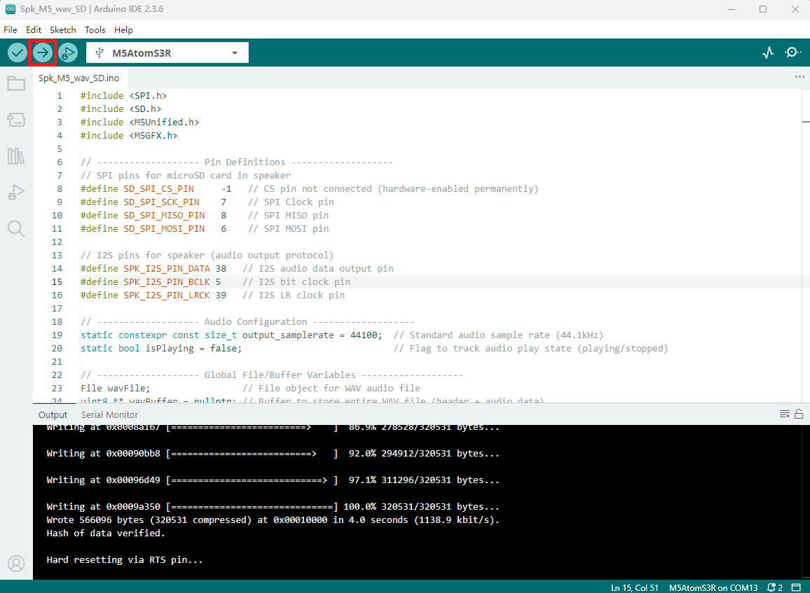
5. Compile and Upload
- 1.Download Mode: Before flashing programs to different devices, download mode is required. This step may vary depending on the main control device used. For details, refer to the device program download tutorial list at the bottom of the Arduino IDE Getting Started Tutorial page to view the specific operation method.
- For AtomS3R, press and hold the reset button (for about 2 seconds) until the internal green LED lights up, then release. At this point, the device has entered download mode and is ready for flashing.
- 2.Select the device port, click the compile/upload button in the upper left corner of the Arduino IDE, and wait for the program to finish compiling and uploading to the device.