

Arduino Quick Start
2. Devices & Examples
3. M5Unified
4. M5GFX
5. Extensions
Unit
Atomic
Tab5
IoT
Accessories
Hat Mini JoyC Arduino Tutorial
1. Preparation
Environment Setup: Refer to the Arduino IDE Quick Start Tutorial to complete the IDE installation, and install the corresponding board manager and required driver libraries according to the development board you are using.
Required Libraries:
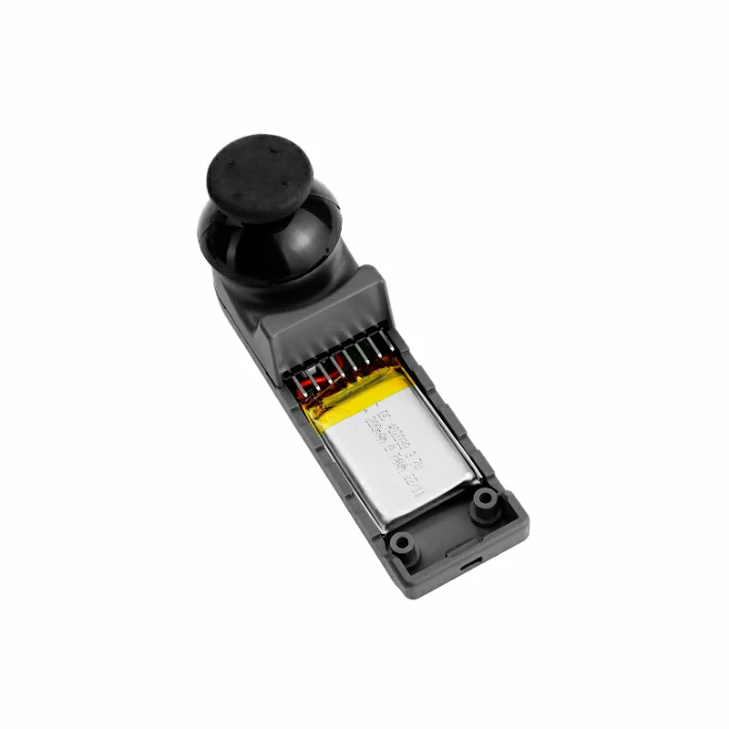
Hardware Used:
2. Precautions
Pin Compatibility
Due to different pin configurations of each host device, please refer to the pin compatibility table in the product documentation before use, and modify the example program according to the actual pin connections.
3. Example Program
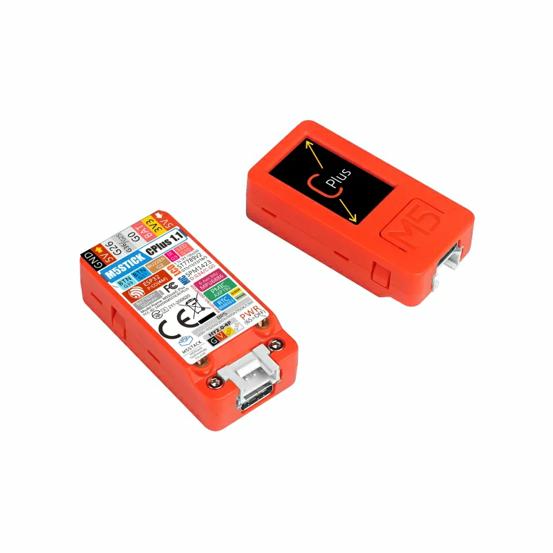
- In this tutorial, the main control device used is StickC Plus, paired with the Hat Mini JoyC module. This joystick module communicates via I2C. Modify the pin definitions in the program according to the actual circuit connections. After stacking the devices, the corresponding I2C IO pins are
G26 (SCL)andG0 (SDA).
cpp
1 2 3 4 5 6 7 8 9 10 11 12 13 14 15 16 17 18 19 20 21 22 23 24 25 26 27 28 29 30 31 32 33 34 35 36 37 38 39 40 41 42 43 44 45 46 47 48 49 50 51 52 53 54 55 56 57 58 59 60 61 62 63 64 65 66 67 68 69 70 71 72 73 74 75
#include "M5Unified.h"
#include "M5HatMiniJoyC.h"

// MiniJoyC I2C pins
#define MiniJoyC_SDA 0
#define MiniJoyC_SCL 26

M5HatMiniJoyC joyc;

// Wait until MiniJoyC is ready
static void waitMiniJoyCReady() {
  while (!joyc.begin(&Wire, MiniJoyC_ADDR, MiniJoyC_SDA, MiniJoyC_SCL, 100000UL)) {
    delay(100);
  }
}

void setup() {
  M5.begin();
  waitMiniJoyCReady();

  M5.Display.setRotation(0);
  M5.Display.setFont(&fonts::FreeMonoBold9pt7b);
  M5.Display.fillScreen(BLACK);
}

void loop() {
  M5.update();

  // Read raw ADC values (0~4095)
  int16_t adc_x = joyc.getADCValue(ADC_X);
  int16_t adc_y = joyc.getADCValue(ADC_Y);

  // Read normalized position (-128~127)
  int8_t pos_x = joyc.getPOSValue(POS_X, _8bit);
  int8_t pos_y = joyc.getPOSValue(POS_Y, _8bit);

  // Display values
  M5.Display.fillScreen(BLACK);
  M5.Display.setTextColor(WHITE, BLACK);

  M5.Display.setCursor(0, 20);
  M5.Display.printf("ADC X:%4d", adc_x);
  M5.Display.setCursor(0, 50);
  M5.Display.printf("ADC Y:%4d", adc_y);

  M5.Display.drawLine(0, 80, 135, 80, ORANGE);

  M5.Display.setCursor(0, 100);
  M5.Display.printf("POS X:%4d", pos_x);
  M5.Display.setCursor(0, 130);
  M5.Display.printf("POS Y:%4d", pos_y);

  M5.Display.drawLine(0, 160, 135, 160, ORANGE);

  M5.Display.setCursor(0, 180);
  M5.Display.printf("BtnVal: %d", joyc.getButtonStatus());

  // Map joystick to RGB888
  uint8_t r = constrain(map(-pos_y, -128, 127, 0, 255), 0, 255);
  uint8_t g = constrain(map( pos_y, -128, 127, 0, 255), 0, 255);
  uint8_t b = constrain(map( pos_x, -128, 127, 0, 255), 0, 255);

  // Center dead zone → white
  if (abs(pos_x) < 8 && abs(pos_y) < 8) {
    r = g = b = 255;
  }

  // Combine to RGB888 (0xRRGGBB)
  uint32_t rgb888 = (r << 16) | (g << 8) | b;

  // Set MiniJoyC LED color
  joyc.setLEDColor(rgb888);

  delay(30);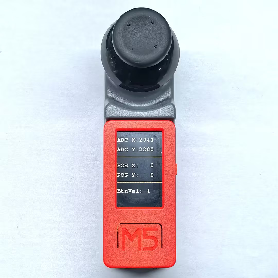
}4. Control Effect
- After the device is powered on, moving the joystick will change the values displayed on the screen, and the RGB LED on the back will change color according to the joystick position. Pressing the joystick button toggles the button state display.
Page Tools