

Arduino Quick Start
2. Devices & Examples
3. M5Unified
4. M5GFX
5. Extensions
Unit
Atomic
Tab5
IoT
Accessories
Unit ChainBus Arduino Tutorial
1. Preparation
- Environment setup: Refer to the Arduino IDE Getting Started Guide to complete IDE installation, and install the corresponding board package and required libraries according to your development board.
- Required libraries:
- Required hardware:


2. Notes
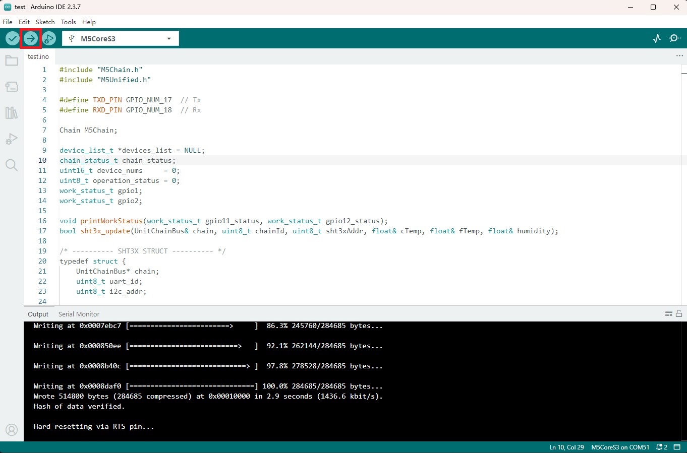
3. Compile & Upload
- 1. Enter download mode: Press and hold the reset button on CoreS3-SE (approximately 2 seconds) until the internal green LED lights up, then release it. The device is now in download mode, waiting for programming.

2. Select the device port and click the compile and upload button in the upper left corner of Arduino IDE. Wait for the program to complete compilation and upload to the device.
4. Example
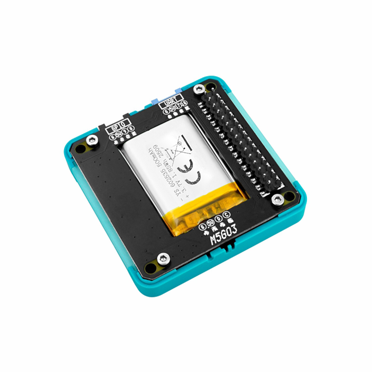
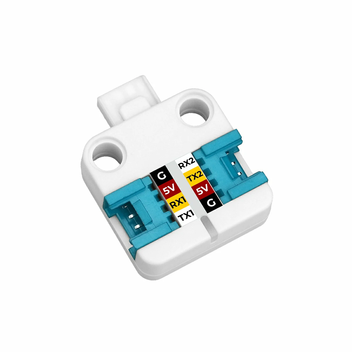
- The main controller used in this tutorial is CoreS3-SE, powered by the Base M5GO Bottom3, using PORT.C. It works with Unit ChainBus and other modules to achieve the demo effects. This module communicates via UART. Modify the pin definitions in the program according to your actual circuit connections. After connection, the corresponding UART IOs are
G17 (RX),G18 (TX).
4.1 I2C Mode
#include "M5Chain.h"
#include "M5Unified.h"

#define TXD_PIN GPIO_NUM_17  // Tx
#define RXD_PIN GPIO_NUM_18  // Rx

Chain M5Chain;

device_list_t *devices_list = NULL;
chain_status_t chain_status;
uint16_t device_nums     = 0;
uint8_t operation_status = 0;
work_status_t gpio1;
work_status_t gpio2;

void printWorkStatus(String gpio_num, work_status_t gpio_status);
bool sht3x_update(UnitChainBus& chain, uint8_t chainId, uint8_t sht3xAddr, float& cTemp, float& fTemp, float& humidity);

/* ---------- SHT3X STRUCT ---------- */
typedef struct {
    UnitChainBus* chain;
    uint8_t uart_id;
    uint8_t i2c_addr;

    float cTemp;
    float fTemp;
    float humidity;

    bool update()
    {
        if (chain == nullptr) return false;
        return sht3x_update(*chain, uart_id, i2c_addr,
                                     cTemp, fTemp, humidity);
    }
} SHT3X_t;

SHT3X_t sht3x;

void setup()
{
    M5.begin();
    M5.Display.clear();
    M5.Display.setFont(&FreeMonoBold12pt7b);
    M5.Display.setTextDatum(middle_center);
    M5.Display.drawCenterString("Unit ChainBus Test", 160, 120);

    Serial.begin(115200);
    Serial.println("Unit ChainBus Test");
    M5Chain.begin(&Serial2, 115200, RXD_PIN, TXD_PIN);

    // Check whether any Unit Chain device is connected
    if (M5Chain.isDeviceConnected()) {
        Serial.println("devices is connected");
        chain_status = M5Chain.getDeviceNum(&device_nums);
        if (chain_status == CHAIN_OK) {
            devices_list          = (device_list_t *)malloc(sizeof(device_list_t));
            devices_list->count   = device_nums;
            devices_list->devices = (device_info_t *)malloc(sizeof(device_info_t) * device_nums);
            // Get detailed device list
            if (M5Chain.getDeviceList(devices_list)) {
                Serial.println("devices list get success");
            } else {
                Serial.println("devices list get failed");
            }
        } else {
            Serial.printf("error status:%d \r\n", chain_status);
            Serial.printf("devices num get failed.\r\n");
        }
    } else {
        Serial.println("devices is not connected.");
    }

    if (devices_list->devices[0].device_type == UNIT_CHAIN_BUS_TYPE_CODE) {
        Serial.println("ID[1] is Unit ChainBus\n");
        chain_status = M5Chain.setChainBusI2cMode(devices_list->devices[0].id, CHAIN_I2C_HIGH_SPEED_400KHZ, &operation_status);// set i2c mode
        if (chain_status == CHAIN_OK && operation_status == 1) {
            Serial.printf("Unit ChainBus ID[%d] set i2c mode success \r\n", devices_list->devices[0].id);
            M5Chain.getChainBusWorkMode(devices_list->devices[0].id, &gpio1, &gpio2);// Read Unit ChainBus GPIO working status
            printWorkStatus("GPIO_1", (work_status_t)gpio1);
            printWorkStatus("GPIO_2", (work_status_t)gpio2);
        } else {
            Serial.printf("Unit ChainBus ID[%d] set i2c mode fail, chain_status:%d  operation_status:%d \r\n", devices_list->devices[0].id, chain_status, operation_status);
        }
        delay(500);

        // Bind SHT3X to this ChainBus
        sht3x.chain    = &M5Chain;
        sht3x.uart_id  = devices_list->devices[0].id;
        sht3x.i2c_addr = 0x44;  // SHT3X I2C address, can get from getChainBusI2cScanAddr

        Serial.printf("\nUnit ENV-III SHT3X bind to ChainBus ID[%d]\r\n", sht3x.uart_id);
    } else {
        Serial.println("ID[1] is NOT Unit ChainBus\n");
        return;
    }

    delay(5);
}

void loop()
{
    if (sht3x.update()) {
        Serial.println("-----SHT3X-----");
        Serial.print("Temperature: ");
        Serial.print(sht3x.cTemp);
        Serial.println(" 'C");
        Serial.print("Humidity: ");
        Serial.print(sht3x.humidity);
        Serial.println("% rH");
        Serial.println("--------------\r\n");

        M5.Display.fillRect(0, 0, 320, 240, TFT_BLACK);
        M5.Display.setCursor(0, 20);
        M5.Display.println("-----SHT3X-----");
        M5.Display.print("Temperature: ");
        M5.Display.print(sht3x.cTemp);
        M5.Display.println(" 'C");
        M5.Display.print("Humidity: ");
        M5.Display.print(sht3x.humidity);
        M5.Display.println("% rH");
        M5.Display.println("---------------\r\n");
    }

    delay(1000);
}

void printWorkStatus(String gpio_num, work_status_t gpio_status)
{
    Serial.print("  >>> " + gpio_num + ": ");
    switch (gpio_status) {
        case CHAIN_NOT_WORK_STATUS:
            Serial.println("Not configured working status");
            break;
        case CHAIN_OUTPUT_WORK_STATUS:
            Serial.println("Output status");
            break;
        case CHAIN_INPUT_WORK_STATUS:
            Serial.println("Input status");
            break;
        case CHAIN_NVIC_WORK_STATUS:
            Serial.println("External interrupt working status");
            break;
        case CHAIN_ADC_WORK_STATUS:
            Serial.println("ADC working status");
            break;
        case CHAIN_I2C_WORK_STATUS:
            Serial.println("I2C working status");
            break;
        default:
            Serial.println("Unrecognized work status");
            break;
    }
}

// Perform one complete SHT3X measurement cycle via Unit ChainBus I2C
bool sht3x_update(UnitChainBus& chain,
                         uint8_t chainId,
                         uint8_t sht3xAddr,
                         float& cTemp,
                         float& fTemp,
                         float& humidity)
{
    uint8_t opStatus = 0;
    chain_status_t status;

    // 1. Send measurement command (high repeatability, clock stretching disabled)
    uint8_t cmd[2] = {0x2C, 0x06};
    status = chain.chainBusI2cWrite(
        chainId,
        sht3xAddr,
        2,
        cmd,
        &opStatus,
        1000
    );

    if (status != CHAIN_OK || opStatus != CHAIN_BUS_OPERATION_SUCCESS) {
        return false;
    }

    // 2. Wait for the measurement to complete
    delay(100);

    // 3. Read 6 bytes of measurement data
    uint8_t data[6] = {0};
    status = chain.chainBusI2cRead(
        chainId,
        sht3xAddr,
        6,
        data,
        &opStatus,
        1000
    );

    if (status != CHAIN_OK || opStatus != CHAIN_BUS_OPERATION_SUCCESS) {
        return false;
    }

    // 4. Convert raw data to temperature and humidity
    cTemp = ((((data[0] * 256.0) + data[1]) * 175.0) / 65535.0) - 45.0;
    fTemp = (cTemp * 1.8) + 32.0;
    humidity = ((((data[3] * 256.0) + data[4]) * 100.0) / 65535.0);

    return true;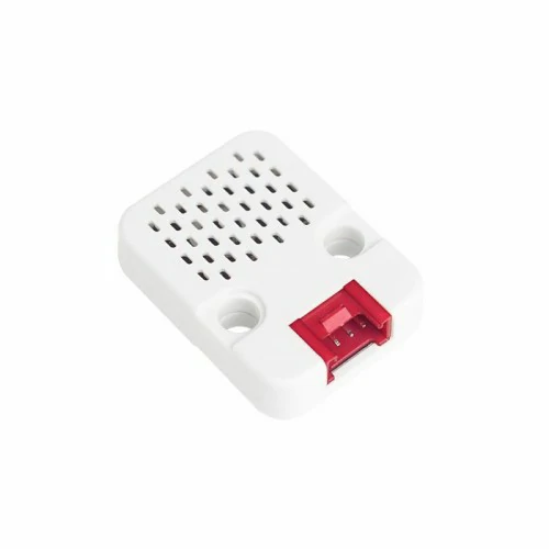
}After power-on, the serial monitor will output information about the connected devices, and read temperature and humidity data from the SHT3X sensor on Unit ENV-III via the Unit ChainBus interface.
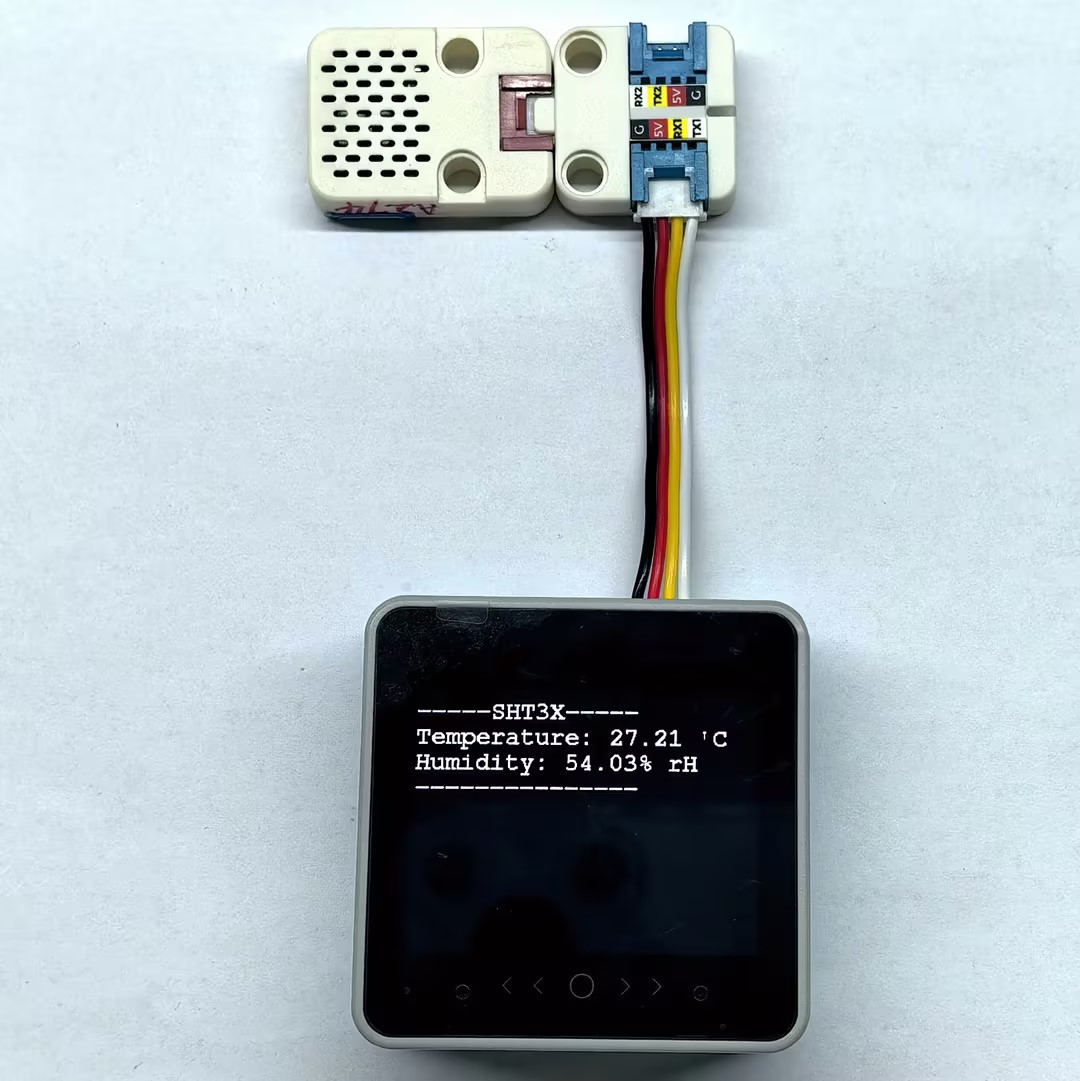
Example serial monitor output:
Unit ChainBus Test
devices is connected
devices list get success
ID[1] is Unit ChainBus

Unit ChainBus ID[1] set i2c mode success
  >>> GPIO_1: I2C working status
  >>> GPIO_2: I2C working status

Unit ENV-III SHT3X bind to ChainBus ID[1]
-----SHT3X-----
Temperature: 27.19 'C
Humidity: 52.88% rH
--------------4.2 Input Mode
#include "M5Chain.h"
#include "M5Unified.h"

#define TXD_PIN GPIO_NUM_17  // Tx
#define RXD_PIN GPIO_NUM_18  // Rx

Chain M5Chain;

device_list_t *devices_list = NULL;
chain_status_t chain_status;
uint16_t device_nums     = 0;
uint8_t operation_status = 0;
work_status_t gpio1;
work_status_t gpio2;

void printWorkStatus(String gpio_num, work_status_t gpio_status);

void setup()
{
    M5.begin();
    M5.Display.clear();
    M5.Display.setFont(&FreeMonoBold12pt7b);
    M5.Display.setTextDatum(middle_center);
    M5.Display.drawCenterString("Unit ChainBus Test", 160, 120);

    Serial.begin(115200);
    Serial.println("Unit ChainBus Test");
    M5Chain.begin(&Serial2, 115200, RXD_PIN, TXD_PIN);

    // Check whether any Unit Chain device is connected
    if (M5Chain.isDeviceConnected()) {
        Serial.println("devices is connected");
        chain_status = M5Chain.getDeviceNum(&device_nums);
        if (chain_status == CHAIN_OK) {
            devices_list          = (device_list_t *)malloc(sizeof(device_list_t));
            devices_list->count   = device_nums;
            devices_list->devices = (device_info_t *)malloc(sizeof(device_info_t) * device_nums);
            // Get detailed device list
            if (M5Chain.getDeviceList(devices_list)) {
                Serial.println("devices list get success");
            } else {
                Serial.println("devices list get failed");
            }
        } else {
            Serial.printf("error status:%d \r\n", chain_status);
            Serial.printf("devices num get failed.\r\n");
        }
    } else {
        Serial.println("devices is not connected.");
    }

    if (devices_list->devices[0].device_type == UNIT_CHAIN_BUS_TYPE_CODE) {
        Serial.println("ID[1] is Unit ChainBus\n");
        chain_status = M5Chain.setChainBusInputMode(devices_list->devices[0].id, CHAIN_GPIO_PIN_1, CHAIN_GPIO_PULL_UP, &operation_status, 3000);// set GPIO1 input mode
        if (chain_status == CHAIN_OK && operation_status == 1) {
            Serial.printf("Unit ChainBus ID[%d] set GPIO1 input mode success \r\n", devices_list->devices[0].id);
            M5Chain.getChainBusWorkMode(devices_list->devices[0].id, &gpio1, &gpio2);// Read Unit ChainBus GPIO working status
            printWorkStatus("GPIO_1", (work_status_t)gpio1);
            printWorkStatus("GPIO_2", (work_status_t)gpio2);
        } else {
            Serial.printf("Unit ChainBus ID[%d] set GPIO1 input mode fail, chain_status:%d  operation_status:%d \r\n", devices_list->devices[0].id, chain_status, operation_status);
        }
        delay(500);
    } else {
        Serial.println("ID[1] is NOT Unit ChainBus\n");
        return;
    }

    delay(5);
}

uint8_t last_button_status = true;

void loop()
{
    uint8_t button_status;
    // Read GPIO1 input level from Unit ChainBus
    chain_status = M5Chain.getChainBusInputLevel(devices_list->devices[0].id, CHAIN_GPIO_PIN_1, &button_status, &operation_status);
    if (chain_status == CHAIN_OK && operation_status == 1) {
        if (button_status != last_button_status) {
            Serial.printf("button status: %d \r\n", button_status);
            last_button_status = button_status;
        }
    } else {
        Serial.printf("get button status failed, chain_status:%d  operation_status:%d \r\n", chain_status,
                      operation_status);
    }

    delay(20);
}

void printWorkStatus(String gpio_num, work_status_t gpio_status)
{
    Serial.print("  >>> " + gpio_num + ": ");
    switch (gpio_status) {
        case CHAIN_NOT_WORK_STATUS:
            Serial.println("Not configured working status");
            break;
        case CHAIN_OUTPUT_WORK_STATUS:
            Serial.println("Output status");
            break;
        case CHAIN_INPUT_WORK_STATUS:
            Serial.println("Input status");
            break;
        case CHAIN_NVIC_WORK_STATUS:
            Serial.println("External interrupt working status");
            break;
        case CHAIN_ADC_WORK_STATUS:
            Serial.println("ADC working status");
            break;
        case CHAIN_I2C_WORK_STATUS:
            Serial.println("I2C working status");
            break;
        default:
            Serial.println("Unrecognized work status");
            break;
    }
}After power-on, the serial monitor will output information about the connected devices, and read the blue button state changes on Unit Dual Button via the Unit ChainBus interface.
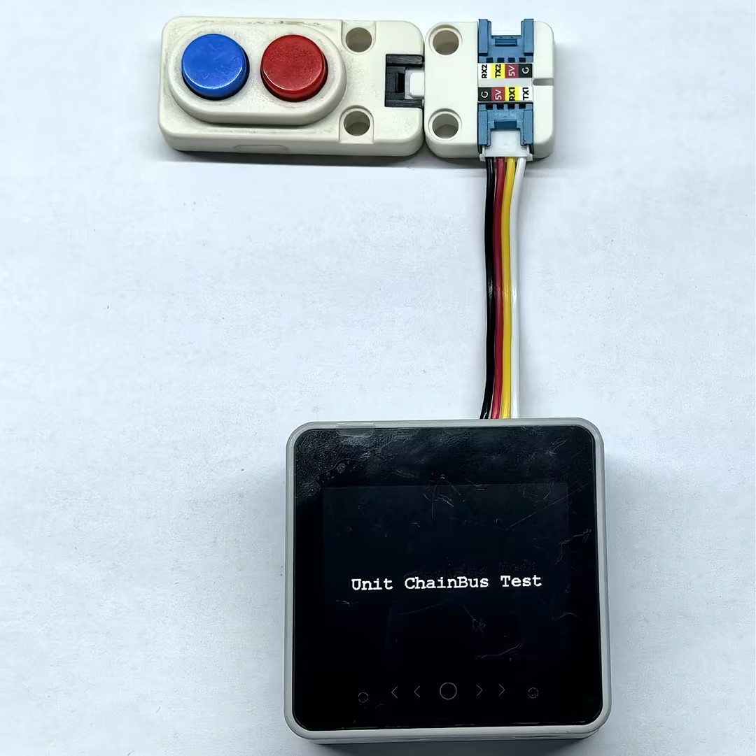
Example serial monitor output:
Unit ChainBus Test
devices is connected
devices list get success
ID[1] is Unit ChainBus

Unit ChainBus ID[1] set GPIO1 input mode success
  >>> GPIO_1: Input status
  >>> GPIO_2: Not configured working status
button status: 0
button status: 14.3 Output Mode
The program below controls both GPIO1 and GPIO2 on Unit ChainBus. GPIO1 toggles between high and low every 500 ms, while GPIO2 is held low. You can connect an LED for observation.
#include "M5Chain.h"
#include "M5Unified.h"

#define TXD_PIN GPIO_NUM_17  // Tx
#define RXD_PIN GPIO_NUM_18  // Rx

Chain M5Chain;

device_list_t *devices_list = NULL;
chain_status_t chain_status;
uint16_t device_nums     = 0;
uint8_t operation_status = 0;
work_status_t gpio1;
work_status_t gpio2;

void printWorkStatus(String gpio_num, work_status_t gpio_status);

void setup()
{
    M5.begin();
    M5.Display.clear();
    M5.Display.setFont(&FreeMonoBold12pt7b);
    M5.Display.setTextDatum(middle_center);
    M5.Display.drawCenterString("Unit ChainBus Test", 160, 120);

    Serial.begin(115200);
    Serial.println("Unit ChainBus Test");
    M5Chain.begin(&Serial2, 115200, RXD_PIN, TXD_PIN);

    if (M5Chain.isDeviceConnected()) {
        Serial.println("devices is connected");
        chain_status = M5Chain.getDeviceNum(&device_nums);
        if (chain_status == CHAIN_OK) {
            devices_list          = (device_list_t *)malloc(sizeof(device_list_t));
            devices_list->count   = device_nums;
            devices_list->devices = (device_info_t *)malloc(sizeof(device_info_t) * device_nums);
            if (M5Chain.getDeviceList(devices_list)) {
                Serial.println("devices list get success");
            } else {
                Serial.println("devices list get failed");
            }
        } else {
            Serial.printf("error status:%d \r\n", chain_status);
            Serial.printf("devices num get failed.\r\n");
        }
    } else {
        Serial.println("devices is not connected.");
    }

    if (devices_list->devices[0].device_type == UNIT_CHAIN_BUS_TYPE_CODE) {
        Serial.println("ID[1] is Unit ChainBus\n");
        chain_status = M5Chain.setChainBusOutputMode(devices_list->devices[0].id, CHAIN_GPIO_PIN_1, CHAIN_GPIO_OUTPUT_PUSHPULL, CHAIN_GPIO_PULL_DOWN, &operation_status, 3000);// set output mode
        chain_status = (chain_status_t)(chain_status &
                    M5Chain.setChainBusOutputMode(devices_list->devices[0].id, CHAIN_GPIO_PIN_2, CHAIN_GPIO_OUTPUT_PUSHPULL, CHAIN_GPIO_PULL_DOWN, &operation_status, 3000));// set output mode
        if (chain_status == CHAIN_OK && operation_status == 1) {
            Serial.printf("Unit ChainBus ID[%d] set output mode success \r\n", devices_list->devices[0].id);
            M5Chain.getChainBusWorkMode(devices_list->devices[0].id, &gpio1, &gpio2);// Read Unit ChainBus GPIO working status
            printWorkStatus("GPIO_1", (work_status_t)gpio1);
            printWorkStatus("GPIO_2", (work_status_t)gpio2);
            M5Chain.setChainBusOutputLevel(devices_list->devices[0].id, CHAIN_GPIO_PIN_2, CHAIN_GPIO_RESET, &operation_status);// set GPIO2 output level - low
        } else {
            Serial.printf("Unit ChainBus ID[%d] set output mode fail, chain_status:%d  operation_status:%d \r\n", devices_list->devices[0].id, chain_status, operation_status);
        }
        delay(500);
    } else {
        Serial.println("ID[1] is NOT Unit ChainBus\n");
        return;
    }

    delay(5);
}

bool flag = false;

void loop()
{
    // change GPIO1 output level
    flag = !flag;
    chain_status = M5Chain.setChainBusOutputLevel(devices_list->devices[0].id, CHAIN_GPIO_PIN_1, flag ? CHAIN_GPIO_SET : CHAIN_GPIO_RESET, &operation_status);
    if (chain_status == CHAIN_OK && operation_status == 1) {
        if (flag) {
            Serial.println("set gpio1 high level");
        } else {
            Serial.println("set gpio1 low level");
        }
    } else {
        Serial.printf("set gpio1 level failed, chain_status:%d  operation_status:%d \r\n", chain_status, operation_status);
    }

    delay(500);
}

void printWorkStatus(String gpio_num, work_status_t gpio_status)
{
    Serial.print("  >>> " + gpio_num + ": ");
    switch (gpio_status) {
        case CHAIN_NOT_WORK_STATUS:
            Serial.println("Not configured working status");
            break;
        case CHAIN_OUTPUT_WORK_STATUS:
            Serial.println("Output status");
            break;
        case CHAIN_INPUT_WORK_STATUS:
            Serial.println("Input status");
            break;
        case CHAIN_NVIC_WORK_STATUS:
            Serial.println("External interrupt working status");
            break;
        case CHAIN_ADC_WORK_STATUS:
            Serial.println("ADC working status");
            break;
        case CHAIN_I2C_WORK_STATUS:
            Serial.println("I2C working status");
            break;
        default:
            Serial.println("Unrecognized work status");
            break;
    }
}After power-on, the serial monitor will output information about the connected devices, and control the LED connected to Unit ChainBus to blink.
Example serial monitor output:
Unit ChainBus Test
devices is connected
devices list get success
ID[1] is Unit ChainBus

Unit ChainBus ID[1] set output mode success
  >>> GPIO_1: Output status
  >>> GPIO_2: Output status
set gpio1 high level
set gpio1 low level
set gpio1 high level
set gpio1 low level4.4 Interrupt Mode
#include "M5Chain.h"
#include "M5Unified.h"

#define TXD_PIN GPIO_NUM_17  // Tx
#define RXD_PIN GPIO_NUM_18  // Rx

Chain M5Chain;

device_list_t *devices_list = NULL;
chain_status_t chain_status;
uint16_t device_nums     = 0;
uint8_t operation_status = 0;
work_status_t gpio1;
work_status_t gpio2;

void printWorkStatus(String gpio_num, work_status_t gpio_status);

void setup()
{
    M5.begin();
    M5.Display.clear();
    M5.Display.setFont(&FreeMonoBold12pt7b);
    M5.Display.setTextDatum(middle_center);
    M5.Display.drawCenterString("Unit ChainBus Nvic Test", 160, 120);

    Serial.begin(115200);
    Serial.println("Unit ChainBus Nvic Test");
    M5Chain.begin(&Serial2, 115200, RXD_PIN, TXD_PIN);

    if (M5Chain.isDeviceConnected()) {
        Serial.println("devices is connected");
        chain_status = M5Chain.getDeviceNum(&device_nums);
        if (chain_status == CHAIN_OK) {
            devices_list          = (device_list_t *)malloc(sizeof(device_list_t));
            devices_list->count   = device_nums;
            devices_list->devices = (device_info_t *)malloc(sizeof(device_info_t) * device_nums);
            if (M5Chain.getDeviceList(devices_list)) {
                Serial.println("devices list get success");
            } else {
                Serial.println("devices list get failed");
            }
        } else {
            Serial.printf("error status:%d \r\n", chain_status);
            Serial.printf("devices num get failed.\r\n");
        }
    } else {
        Serial.println("devices is not connected.");
    }

    if (devices_list->devices[0].device_type == UNIT_CHAIN_BUS_TYPE_CODE) {
        Serial.println("ID[1] is Unit ChainBus\n");
        // Configure GPIO1 as NVIC (external interrupt) mode, rising edge trigger
        chain_status = M5Chain.setChainBusNvicMode(devices_list->devices[0].id, CHAIN_GPIO_PIN_1, CHAIN_GPIO_PULL_UP,
                                                    CHAIN_GPIO_MODE_IT_RISING, &operation_status);
        if (chain_status == CHAIN_OK && operation_status == 1) {
            Serial.printf("ChainBus ID[%d] set gpio1 nvic mode RISING success \r\n", devices_list->devices[0].id);
        } else {
            Serial.printf("ChainBus ID[%d] set gpio1 nvic mode RISING fail, chain_status:%d  operation_status:%d \r\n",
                            devices_list->devices[0].id, chain_status, operation_status);
        }

        // Configure GPIO2 as NVIC (external interrupt) mode, rising and falling edge trigger
        chain_status = M5Chain.setChainBusNvicMode(devices_list->devices[0].id, CHAIN_GPIO_PIN_2, CHAIN_GPIO_PULL_UP,
                                                    CHAIN_GPIO_MODE_IT_RISING_FALLING, &operation_status);
        if (chain_status == CHAIN_OK && operation_status == 1) {
            Serial.printf("ChainBus ID[%d] set gpio2 nvic mode RISING_FALLING success \r\n", devices_list->devices[0].id);
        } else {
            Serial.printf("ChainBus ID[%d] set gpio2 mode RISING_FALLING fail, chain_status:%d  operation_status:%d \r\n",
                            devices_list->devices[0].id, chain_status, operation_status);
        }
        M5Chain.getChainBusWorkMode(devices_list->devices[0].id, &gpio1, &gpio2);
        printWorkStatus("GPIO_1", (work_status_t)gpio1);
            printWorkStatus("GPIO_2", (work_status_t)gpio2);
        delay(500);
    } else {
        Serial.println("ID[1] is NOT Unit ChainBus\n");
        return;
    }

    delay(5);
}

void loop()
{
    if (devices_list) {
        if (devices_list->devices[0].device_type == UNIT_CHAIN_BUS_TYPE_CODE) {
            // Check whether GPIO1 or GPIO2 is configured as NVIC mode
            if (gpio1 == CHAIN_NVIC_WORK_STATUS || gpio2 == CHAIN_NVIC_WORK_STATUS) {
                uint16_t nvic_status = 0;
                while (M5Chain.getChainBusNvicTriggerStatus(devices_list->devices[0].id, &nvic_status)) {
                    Serial.println("**********************************");
                    Serial.printf("ChainBus ID[%d] nvic status: 0x%04x \r\n", devices_list->devices[0].id, nvic_status);
                }
            }
        } else {
            Serial.printf("ChainBus ID[%d] get work mode fail, chain_status:%d  operation_status:%d \r\n",
                          devices_list->devices[0].id, chain_status, operation_status);
        }
    }

    delay(40);
}

void printWorkStatus(String gpio_num, work_status_t gpio_status)
{
    Serial.print("  >>> " + gpio_num + ": ");
    switch (gpio_status) {
        case CHAIN_NOT_WORK_STATUS:
            Serial.println("Not configured working status");
            break;
        case CHAIN_OUTPUT_WORK_STATUS:
            Serial.println("Output status");
            break;
        case CHAIN_INPUT_WORK_STATUS:
            Serial.println("Input status");
            break;
        case CHAIN_NVIC_WORK_STATUS:
            Serial.println("External interrupt working status");
            break;
        case CHAIN_ADC_WORK_STATUS:
            Serial.println("ADC working status");
            break;
        case CHAIN_I2C_WORK_STATUS:
            Serial.println("I2C working status");
            break;
        default:
            Serial.println("Unrecognized work status");
            break;
    }
}After power-on, the serial monitor will output information about the connected devices and read the interrupt trigger status of the Unit Dual Button connected to Unit ChainBus. Pressing the blue button triggers a rising-edge interrupt, and the serial port returns the corresponding message once; pressing the red button triggers both rising- and falling-edge interrupts, and the serial port returns the corresponding message twice. In the returned hexadecimal value, the low byte indicates the pin level state before the interrupt was triggered, and the high byte indicates the GPIO number that triggered the interrupt.

Example serial monitor output:
Unit ChainBus Nvic Test
devices is connected
devices list get success
ID[1] is Unit ChainBus

ChainBus ID[1] set gpio1 nvic mode RISING success
ChainBus ID[1] set gpio2 nvic mode RISING_FALLING success
  >>> GPIO_1: External interrupt working status
  >>> GPIO_2: External interrupt working status
**********************************
ChainBus ID[1] nvic status: 0x0100
**********************************
ChainBus ID[1] nvic status: 0x0201
**********************************
ChainBus ID[1] nvic status: 0x02004.5 ADC Mode
#include "M5Chain.h"
#include "M5Unified.h"

#define TXD_PIN GPIO_NUM_17  // Tx
#define RXD_PIN GPIO_NUM_18  // Rx

Chain M5Chain;

device_list_t *devices_list = NULL;
chain_status_t chain_status;
uint16_t device_nums     = 0;
uint8_t operation_status = 0;
work_status_t gpio1;
work_status_t gpio2;

void printWorkStatus(String gpio_num, work_status_t gpio_status);

void setup()
{
    M5.begin();
    M5.Display.clear();
    M5.Display.setFont(&FreeMonoBold12pt7b);
    M5.Display.setTextDatum(middle_center);
    M5.Display.drawCenterString("Unit ChainBus Test", 160, 120);

    Serial.begin(115200);
    Serial.println("Unit ChainBus Test");
    M5Chain.begin(&Serial2, 115200, RXD_PIN, TXD_PIN);

    if (M5Chain.isDeviceConnected()) {
        Serial.println("devices is connected");
        chain_status = M5Chain.getDeviceNum(&device_nums);
        if (chain_status == CHAIN_OK) {
            devices_list          = (device_list_t *)malloc(sizeof(device_list_t));
            devices_list->count   = device_nums;
            devices_list->devices = (device_info_t *)malloc(sizeof(device_info_t) * device_nums);
            if (M5Chain.getDeviceList(devices_list)) {
                Serial.println("devices list get success");
            } else {
                Serial.println("devices list get failed");
            }
        } else {
            Serial.printf("error status:%d \r\n", chain_status);
            Serial.printf("devices num get failed.\r\n");
        }
    } else {
        Serial.println("devices is not connected.");
    }

    if (devices_list->devices[0].device_type == UNIT_CHAIN_BUS_TYPE_CODE) {
        Serial.println("ID[1] is Unit ChainBus\n");

        // Configure GPIO1 as ADC input mode
        chain_status = M5Chain.setChainBusAdcMode(devices_list->devices[0].id, CHAIN_GPIO_PIN_1, &operation_status, 3000);
        if (chain_status == CHAIN_OK && operation_status == 1) {
            Serial.printf("ChainBus ID[%d] set GPIO1 adc mode success \r\n", devices_list->devices[0].id);
        } else {
            Serial.printf("ChainBus ID[%d] set GPIO1 adc mode fail, chain_status:%d  operation_status:%d \r\n",
                            devices_list->devices[0].id, chain_status, operation_status);
        }

        M5Chain.getChainBusWorkMode(devices_list->devices[0].id, &gpio1, &gpio2);
        printWorkStatus("GPIO_1", (work_status_t)gpio1);
            printWorkStatus("GPIO_2", (work_status_t)gpio2);
        delay(500);
    } else {
        Serial.println("ID[1] is NOT Unit ChainBus\n");
        return;
    }

    delay(5);
}

uint16_t last_adc_value = 0;

void loop()
{
    uint16_t adc_value;
    chain_status = M5Chain.getChainBusAdcValue(devices_list->devices[0].id, CHAIN_GPIO_PIN_1, &adc_value, &operation_status);
    if (chain_status == CHAIN_OK && operation_status == 1) {
        if (abs(adc_value - last_adc_value) > 4) {// Print ADC value only when the change exceeds the threshold
            Serial.printf("\nADC value: %d \r\n", adc_value);
            last_adc_value = adc_value;
        }
    } else {
        Serial.printf("get ADC value failed, chain_status:%d  operation_status:%d \r\n", chain_status, operation_status);
    }

    delay(100);
}

void printWorkStatus(String gpio_num, work_status_t gpio_status)
{
    Serial.print("  >>> " + gpio_num + ": ");
    switch (gpio_status) {
        case CHAIN_NOT_WORK_STATUS:
            Serial.println("Not configured working status");
            break;
        case CHAIN_OUTPUT_WORK_STATUS:
            Serial.println("Output status");
            break;
        case CHAIN_INPUT_WORK_STATUS:
            Serial.println("Input status");
            break;
        case CHAIN_NVIC_WORK_STATUS:
            Serial.println("External interrupt working status");
            break;
        case CHAIN_ADC_WORK_STATUS:
            Serial.println("ADC working status");
            break;
        case CHAIN_I2C_WORK_STATUS:
            Serial.println("I2C working status");
            break;
        default:
            Serial.println("Unrecognized work status");
            break;
    }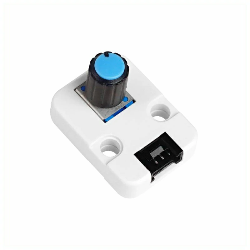
}After power-on, the serial monitor will output information about the connected devices, and read the ADC value from Unit Angle via the Unit ChainBus interface.
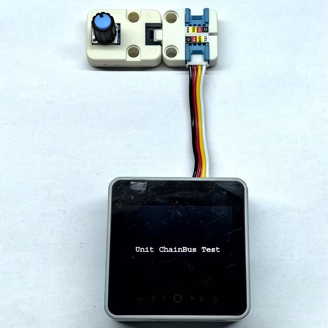
Example serial monitor output:
Unit ChainBus Test
devices is connected
devices list get success
ID[1] is Unit ChainBus

ChainBus ID[1] set GPIO1 adc mode success
  >>> GPIO_1: ADC working status
  >>> GPIO_2: Not configured working status

ADC value: 4095