Arduino Quick Start
2. Devices & Examples
3. M5Unified
4. M5GFX
5. Extensions
Unit
Atomic
Tab5
IoT
Accessories
Unit Heart Arduino Arduino Tutorial
1. Preparation
Environment setup: Refer to the Arduino IDE Getting Started Guide to install the IDE, and install the appropriate board manager and required libraries for the target development board.
Required libraries:
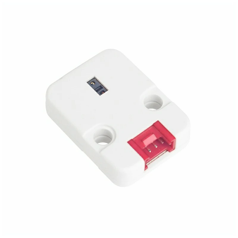
Hardware used:
2. Notes
Pin Compatibility
Each host device has different pin assignments. Please refer to the Pin Compatibility Table in the product documentation and modify the example code according to your actual wiring.
3. Example
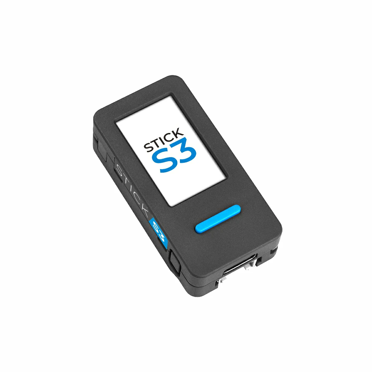
- This guide uses StickS3 as the controller with the Unit Heart module. The heart rate module communicates via I2C. Adjust the pin definitions in the code according to your wiring; when stacked, the I2C pins are
G9 (SCL)andG10 (SDA).
cpp
1 2 3 4 5 6 7 8 9 10 11 12 13 14 15 16 17 18 19 20 21 22 23 24 25 26 27 28 29 30 31 32 33 34 35 36 37 38 39 40 41 42 43 44 45 46 47
#include "M5Unified.h"
#include "MAX30100.h"
#define SAMPLING_RATE MAX30100_SAMPRATE_100HZ
#define IR_LED_CURRENT MAX30100_LED_CURR_24MA
#define RED_LED_CURRENT MAX30100_LED_CURR_27_1MA
#define PULSE_WIDTH MAX30100_SPC_PW_1600US_16BITS
#define HIGHRES_MODE true
MAX30100 sensor; // Instantiate a MAX30100 sensor class
void setup()
{
M5.begin();
M5.Power.begin(); // Init power
Serial.print("Initializing MAX30100..");
while (!sensor.begin()) { // Initialize the sensor
M5.Lcd.setCursor(50, 100);
M5.Lcd.println("Sensor not found");
delay(1000);
}
M5.Lcd.setRotation(3);
M5.Lcd.fillScreen(BLACK);
M5.Lcd.setFont(&fonts::FreeMonoBold12pt7b);
M5.Lcd.setTextSize(1.5);
// Set up the wanted parameters
sensor.setMode(MAX30100_MODE_SPO2_HR);
sensor.setLedsCurrent(IR_LED_CURRENT, RED_LED_CURRENT);
sensor.setLedsPulseWidth(PULSE_WIDTH);
sensor.setSamplingRate(SAMPLING_RATE);
sensor.setHighresModeEnabled(HIGHRES_MODE);
}
void loop()
{
uint16_t ir, red;
sensor.update(); // Update sensor data
if (sensor.getRawValues(&ir, &red)) { // if get data
M5.Lcd.setCursor(5, 20);
M5.Lcd.printf("IR: %d", ir);
M5.Lcd.setCursor(5, 70);
M5.Lcd.printf("RED: %d", red);
}
delay(100); // Appropriate delay
M5.Lcd.fillScreen(BLACK);
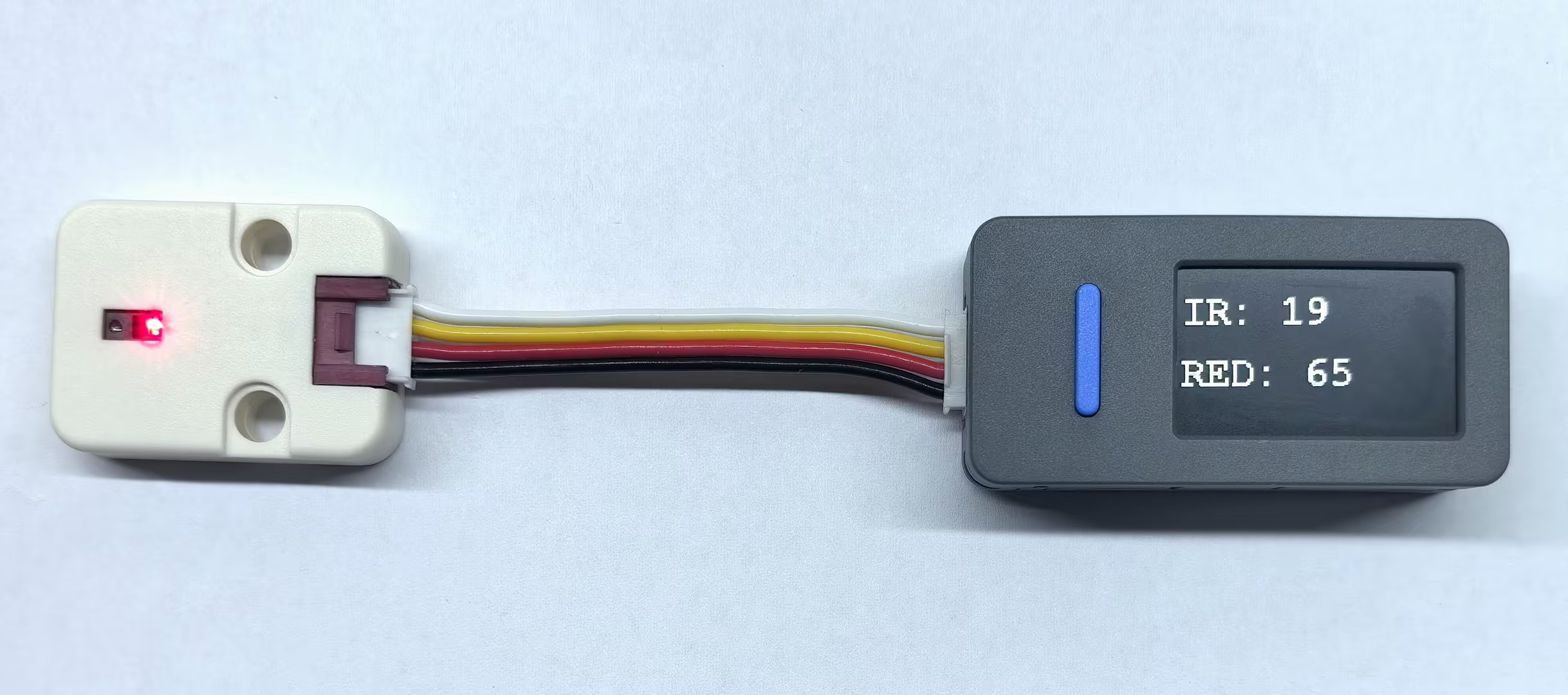
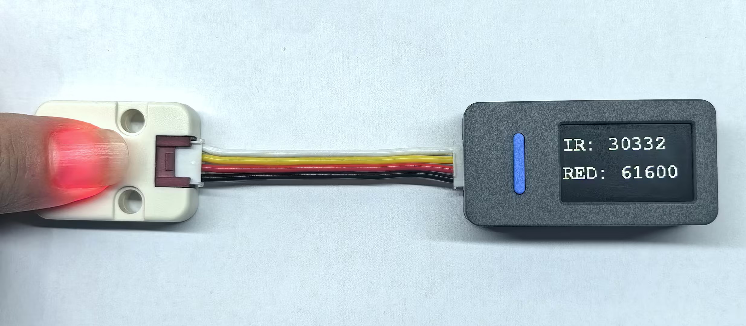
}4. Heart Rate Raw Data Detection
- After powering up, the screen displays the raw infrared and red light data from the MAX30100 sensor. Place your finger on the sensor area of the heart rate module and observe the value changes on the screen, which fluctuate with blood flow.