

Arduino Quick Start
2. Devices & Examples
3. M5Unified
4. M5GFX
5. Extensions
Unit
Module
Atomic
Tab5
IoT
Accessories
Atomic PWM Base Arduino Tutorial
1. Preparation
Environment Configuration: Refer to the Arduino IDE Quick Start Tutorial to install the IDE, add the board manager entries for your board, and install any required drivers and libraries.
Required driver libraries:
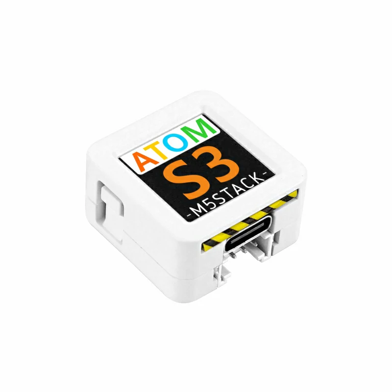
Hardware used:

2. Example
- In this tutorial the main controller is the AtomS3 paired with the Atomic PWM Base. The PWM output pin is
G5 (SIGNAL).
cpp
1 2 3 4 5 6 7 8 9 10 11 12 13 14 15 16 17 18 19 20 21 22 23 24 25 26 27 28 29
#include "M5Unified.h"

#define SIGNAL 5 // PWM signal output pin

int freq        = 10000; // 10kHz
int resolution  = 10;    // Duty cycle resolution in bits (10-bit = 0 to 1023)

void setup() {
    M5.begin();

    M5.Display.setTextColor(GREEN);
    M5.Display.setTextDatum(middle_center);
    M5.Display.setFont(&fonts::Orbitron_Light_24);
    M5.Display.drawString("PWM", M5.Display.width() / 2, M5.Display.height() / 2);

    ledcAttach(SIGNAL, freq, resolution);// Bind the pin, frequency, and resolution
}

void loop() {
    for (int i = 0; i < 500; i++) {
        ledcWrite(SIGNAL, i);// Update the PWM duty cycle
        delay(2);
    }

    for (int i = 500; i > 0; i--) {
        ledcWrite(SIGNAL, i);
        delay(2);
    }
}3. Compile and Upload
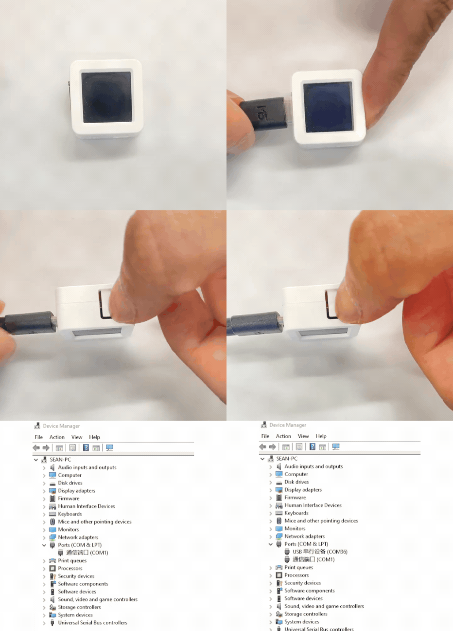
- 1. To enter download mode on AtomS3: press and hold the reset button for about 2 seconds until the internal green LED lights, then release — the device will enter download mode and is ready for flashing. The green LED turns off after the button is released, confirming that the device is in download mode.
Note
Different devices require different steps to enter download mode before flashing. See the device-specific download instructions at the bottom of the Arduino IDE Quick Start Tutorial page for details.
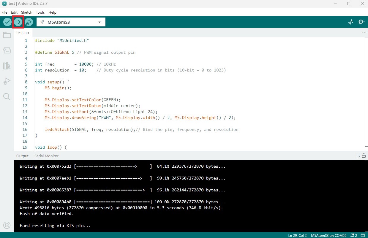
- 2. Select the device port, then click the compile & upload button in the Arduino IDE (top-left). Wait for the sketch to finish compiling and uploading to the device.
4. PWM output to control LED strip brightness
- After power-up the device will start outputting the PWM signal. The LED strip will gradually brighten, then dim, and repeat the cycle.
Page Tools