

Arduino 上手教程
2. 设备开发 & 案例程序
3. M5Unified
4. M5GFX
5. 拓展模块
Unit
Atomic
Tab5
IoT
Unit Glass2 Arduino 使用教程
1.准备工作
- 环境配置:参考 Arduino IDE 上手教程 完成 IDE 安装,并根据实际使用的开发板安装对应的板管理与需要的驱动库。
- 使用到的驱动库:
- 使用到的硬件产品:
2.案例程序
编译要求
M5Stack 板管理版本 >= 3.2.2
M5Unified 库版本 >= 0.2.7
M5GFX 库版本 >= 0.2.9
M5Unified 库版本 >= 0.2.7
M5GFX 库版本 >= 0.2.9
cpp
1 2 3 4 5 6 7 8 9 10 11 12 13 14 15 16 17 18 19 20 21 22 23 24 25 26 27 28 29 30 31 32 33 34 35 36 37 38
#include <M5UnitGLASS2.h>
#include <M5Unified.h>

#define M5UNITGLASS2_ADDR 0x3C  // For Unit Glass2, 0x3C is default, and 0x3D is modified.

int index_unit_glass2;

void setup() {
  auto cfg = M5.config();
  cfg.external_display.unit_glass2 = true;
  M5.begin(cfg);

  index_unit_glass2 = M5.getDisplayIndex(m5::board_t::board_M5UnitGLASS2);
  M5.Displays(index_unit_glass2).setTextSize(2);
  M5.Displays(index_unit_glass2).clear();
}

void loop() {
  M5.Displays(index_unit_glass2).setCursor(0, 0);
  M5.Displays(index_unit_glass2).print("This is \nUnit \nGlass2");
  delay(1000);
  M5.Displays(index_unit_glass2).clear();

  M5.Displays(index_unit_glass2).drawRect(0, 0, 128, 64, 0xFFFF);  // x, y, w, h, color
  delay(500);
  M5.Displays(index_unit_glass2).drawCircle(20, 20, 15, 0xFFFF);  // x, y, r, color
  delay(500);
  M5.Displays(index_unit_glass2).fillArc(50, 45, 17, 20, 100, 330, 0xFFFF);  // x, y, r0, r1, angle0, angle1, color
  delay(500);
  M5.Displays(index_unit_glass2).fillRect(45, 10, 25, 10, 0xFFFF);  // x, y, w, h, color
  delay(500);
  M5.Displays(index_unit_glass2).fillTriangle(90, 10, 80, 40, 110, 55, 0xFFFF);  // x0, y0, x1, y1, x2, y2, color
  delay(500);
  M5.Displays(index_unit_glass2).drawLine(110, 0, 128, 64, 0xFFFF);  // x0, y0, x1, y1, color
  delay(1000);

  M5.Displays(index_unit_glass2).clear();
}运行效果:
3.I2C地址修改
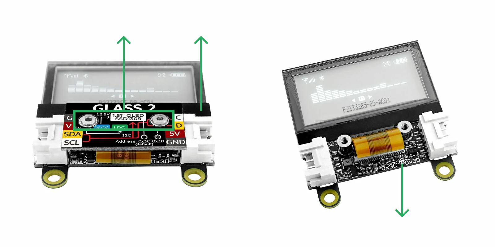
如上图所示,用六角扳手取下两颗螺丝,向上取下盖板,推开屏幕排线,露出圆圈里的两个半圆形焊盘。在圆圈内点锡使两个焊盘导通,即可将 I2C 地址修改为 0x3D;移除点锡即可恢复为 0x3C。
I2C 地址若修改为 0x3D,需要在程序中添加宏定义 #define M5UNITGLASS2_ADDR 0x3D。两个 HY2.0-4P Grove 接口是连通的,可互换使用,用于连接其他 I2C 设备。
4.API
Page Tools