

Arduino入門
2. デバイス&サンプル
3. M5Unified
4. M5GFX
5. 拡張モジュール&サンプル
Unit
Atomic
Tab5
IoT
アクセサリー
Atomic HDriver Base Arduino 使用チュートリアル
1. 準備作業
環境構築:Arduino IDE の導入と各ボードに対応したボードマネージャや必要なドライバ/ライブラリのインストールについては、Arduino IDE クイックスタート を参照してください。
使用するドライバライブラリ:
使用するハードウェア製品:

2. サンプルプログラム
- 本チュートリアルでは AtomS3 をメインコントローラとして Atomic HDriver Base を使用します。信号の出力ピンは
G6 (IN1)とG7 (IN2)です。
cpp
1 2 3 4 5 6 7 8 9 10 11 12 13 14 15 16 17 18 19 20 21 22 23 24 25 26 27 28 29 30 31 32 33 34 35 36 37 38 39 40 41 42 43 44 45 46 47 48 49 50
#include "M5Unified.h"

const int IN1_PIN       = 6;
const int IN2_PIN       = 7;
const int VIN_PIN       = 8;
const int FAULT_PIN     = 5;

int freq          = 10000;
int resolution    = 10;
bool direction    = true;

void setup() {
    M5.begin();

    M5.Display.setTextColor(GREEN);
    M5.Display.setTextDatum(middle_center);
    M5.Display.setFont(&fonts::Orbitron_Light_24);
    M5.Display.drawString("H-Driver", M5.Display.width() / 2, M5.Display.height() / 2);

    ledcAttach(IN1_PIN, freq, resolution);
    ledcAttach(IN2_PIN, freq, resolution);
    pinMode(VIN_PIN, INPUT);
    pinMode(FAULT_PIN, INPUT);
    ledcWrite(IN1_PIN, 0);
    ledcWrite(IN2_PIN, 0);
}

void loop() {
    if (M5.BtnA.pressedFor(1000)) {
        ledcWrite(IN1_PIN, 0);
        ledcWrite(IN2_PIN, 0);
    }

    if (M5.BtnA.wasPressed()) {
        if (direction) {
            ledcWrite(IN1_PIN, 300);
            ledcWrite(IN2_PIN, 0);
        } else {
            ledcWrite(IN1_PIN, 0);
            ledcWrite(IN2_PIN, 300);
        }
        direction = !direction;
    }

    M5.update();
    if (digitalRead(FAULT_PIN) == 0) {
        M5.Display.clear();
        M5.Display.drawString("FAULT!", M5.Display.width() / 2, M5.Display.height() / 2);
    }
}3. コンパイルとアップロード
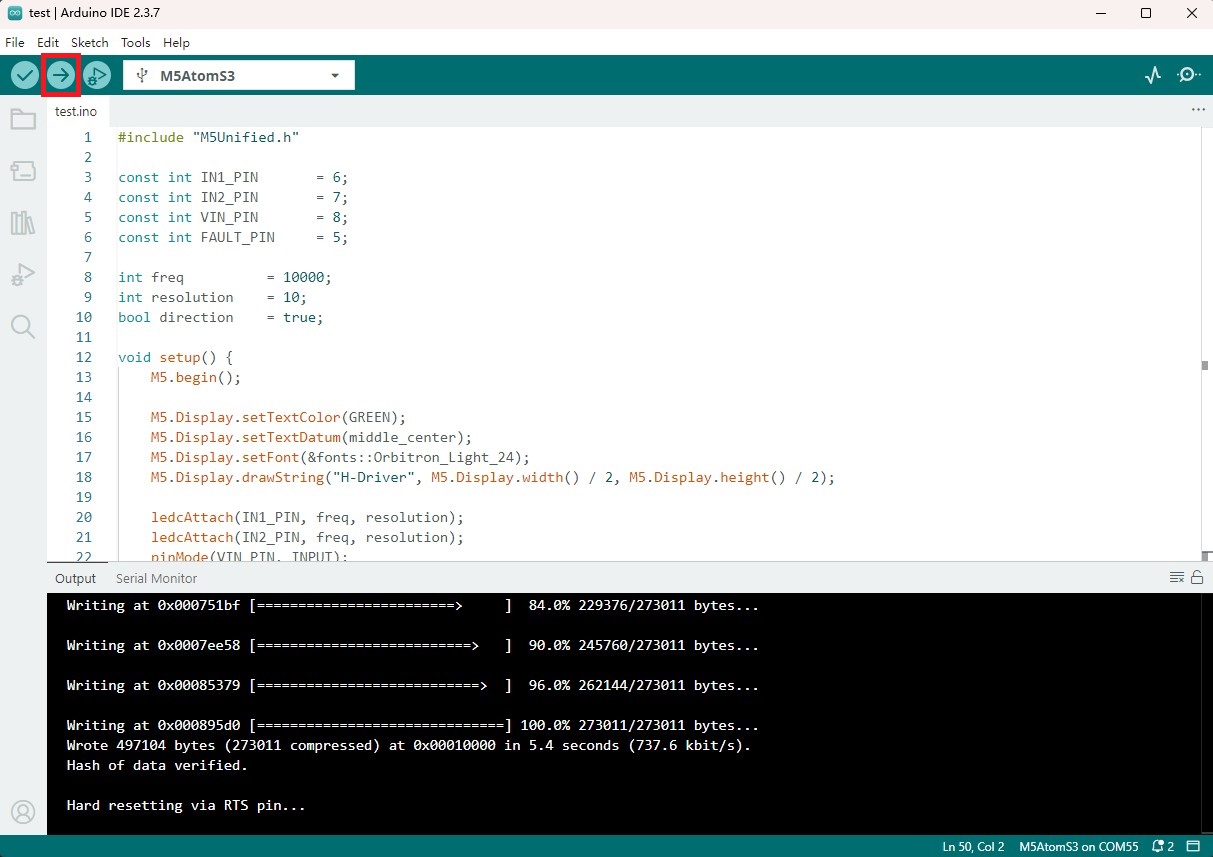
- 1. AtomS3 をダウンロードモードにするには、リセットボタンを約2秒間長押しし、内部の緑色LEDが点灯したら離します。これでデバイスはダウンロードモードに入り、書き込み待ちになります。
説明
書き込み前にダウンロードモードに入る手順はデバイスによって異なります。詳しくは Arduino IDE クイックスタート ページ下部のデバイス別書き込み手順を参照してください。
- 2. デバイスのシリアルポートを選択し、Arduino IDE の左上にあるコンパイル&アップロードボタンをクリックします。スケッチのコンパイルと書き込みが完了するまで待ちます。
4. 直流電機制御
- 通電後、デバイス画面のボタンを押すと直流モーターが正転開始します。もう一度ボタンを押すとモーターが逆転します。ボタンを1秒長押しするとモーターが停止します。(下記のビデオで使用されているのは N20 直流振動モーターです)
Page Tools