Arduino 上手教程
2. 设备开发 & 案例程序
3. M5Unified
4. M5GFX
5. 拓展模块
Unit
Base
IoT
Unit RF433 Arduino 使用教程
1. 准备工作
环境配置: 参考 Arduino IDE 上手教程完成 IDE 安装,并根据实际使用的开发板安装对应的板管理,与需要的驱动库。
使用到的驱动库:
注意
需要在 GitHub 上下载最新的库版本,库地址: RF433any - GitHub,请勿在 Arduino Library 中下载。(如有疑问,请参考此教程)
- 使用到的硬件产品:

2. 注意事项
一组收发装置
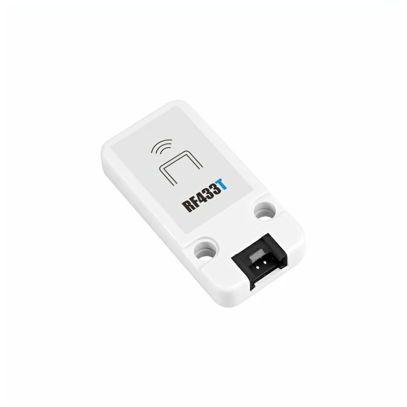
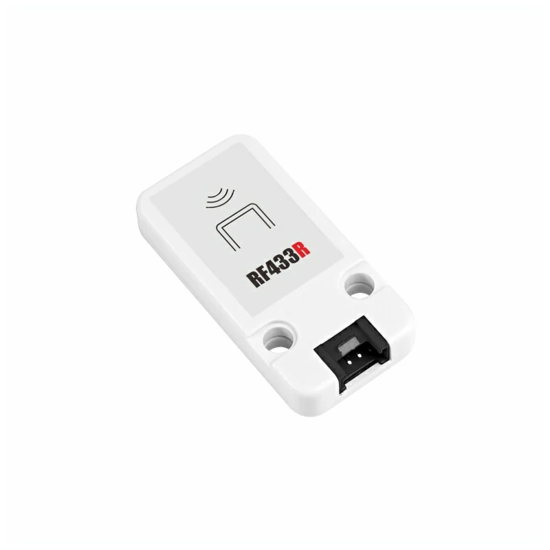
本套 RF433 装置是成对使用的,需要一个 Unit RF433T 作为发送模块,一个 Unit RF433R 作为接收模块。
引脚兼容性
由于每款主机的引脚配置不同,使用前请参考产品文档中的 RF433T 引脚兼容表 和 RF433R 引脚兼容表,并根据实际引脚连接情况修改案例程序。
3. 案例程序
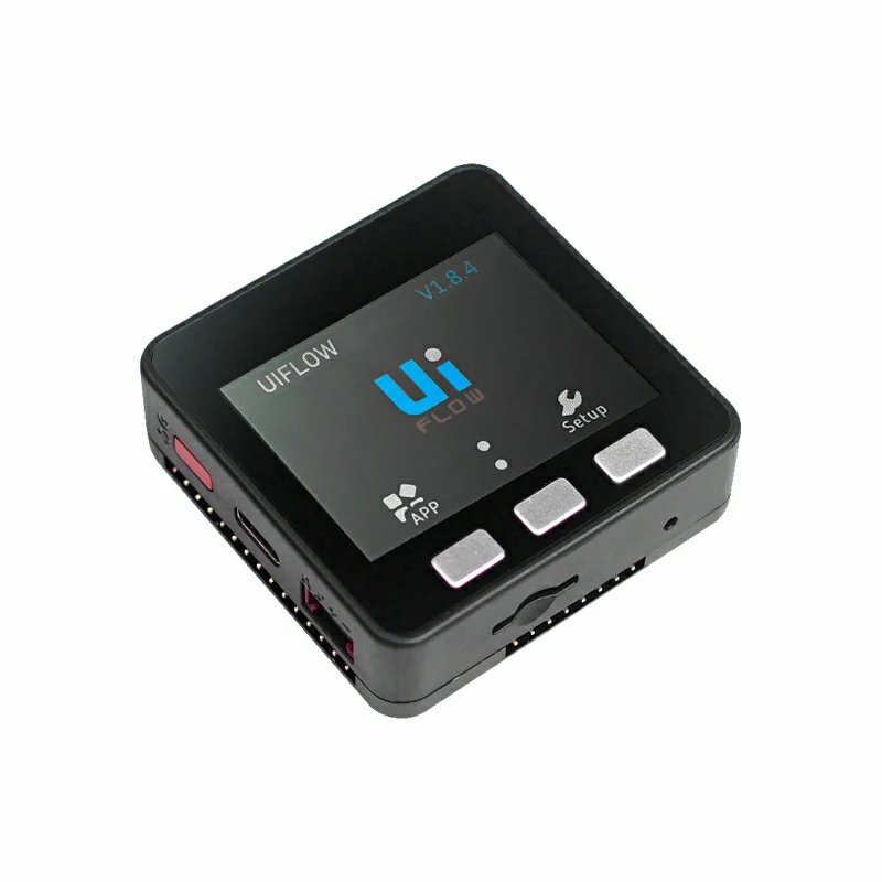
- 本教程中使用 Basic v2.7 搭配 Unit RF433T 作为发射端,CoreS3 搭配 Unit RF433R 作为接收端。两个模块在电路连接中分为 DOUT 和 DIN 两种,请根据实际的电路连接修改程序中的引脚定义。
3.1 RF433T 发射端
cpp
1 2 3 4 5 6 7 8 9 10 11 12 13 14 15 16 17 18 19 20 21 22 23 24 25 26 27 28 29 30 31 32 33 34 35 36 37 38 39 40 41 42 43 44 45 46 47 48 49 50 51 52 53 54 55 56 57 58 59 60 61 62 63 64 65 66 67 68 69 70 71 72 73 74 75 76 77 78 79 80 81 82 83 84 85 86
#include <M5Unified.h>

#define TX_PIN 21

uint8_t data[5] = {0xAA, 0x55, 0x01, 0x02, 0x03};

void pulse(int high, int low) {
    digitalWrite(TX_PIN, HIGH);
    delayMicroseconds(high);
    digitalWrite(TX_PIN, LOW);
    delayMicroseconds(low);
}

void sendCorrected() {
    noInterrupts();

    // 1. 长时间保持低电平,确保接收端准备好
    digitalWrite(TX_PIN, LOW);
    delayMicroseconds(10000);

    // 2. 发送明确的同步序列
    pulse(5000, 2500);  // 长同步脉冲
    pulse(2500, 1250);  // 短同步脉冲

    // 3. 发送数据开始标记 - 与数据位明显不同的时序
    pulse(8000, 4000);  // 超长脉冲标记数据开始

    // 4. 发送实际数据
    for (int byte = 0; byte < 5; byte++) {
        for (int bit = 7; bit >= 0; bit--) {
            if (data[byte] & (1 << bit)) {
                pulse(600, 300);  // 发送1
            } else {
                pulse(300, 600);  // 发送0
            }
        }
    }

    // 5. 数据结束标记
    pulse(8000, 10000);

    interrupts();
}

void setup() {
    M5.begin();
    Serial.begin(115200);

    pinMode(TX_PIN, OUTPUT);
    digitalWrite(TX_PIN, LOW);

    M5.Display.fillRect(0, 0, 320, 240, WHITE);
    M5.Display.setTextColor(BLACK);
    M5.Display.setFont(&fonts::FreeMonoBold12pt7b);
    M5.Display.setCursor(0, 0);
    M5.Display.println("Corrected RF433T");
    M5.Display.println("Click Btn A to send");

    Serial.println("Corrected RF433 Transmitter Ready");
}

void loop() {
    M5.update();

    if (M5.BtnA.wasPressed()) {
        Serial.println("SEND CORRECTED");

        // 只发送一次,避免重复干扰
        sendCorrected();
        delay(100);

        Serial.print("Sent: ");
        for (int i = 0; i < 5; i++) {
            Serial.printf("%02X ", data[i]);
        }
        Serial.println();

        M5.Display.print("Sent: ");
        for (int i = 0; i < 5; i++) {
            M5.Display.printf("%02X ", data[i]);
        }
        M5.Display.println("");
    }

    delay(10);
}3.2 RF433R 接收端
cpp
1 2 3 4 5 6 7 8 9 10 11 12 13 14 15 16 17 18 19 20 21 22 23 24 25 26 27 28 29 30 31 32 33 34 35 36 37 38 39 40 41 42 43 44 45 46 47 48 49 50 51 52 53 54 55 56 57
#include "RF433any.h"
#include <M5Unified.h>

#define PIN_RFINPUT  1

void setup() {
    M5.begin();
    M5.Display.fillRect(0, 0, 320, 240, WHITE);
    M5.Display.setTextColor(BLACK);
    M5.Display.setFont(&fonts::FreeMonoBold12pt7b);
    M5.Display.setCursor(0, 0);
    M5.Display.println("RF433 Receiver");
    pinMode(PIN_RFINPUT, INPUT);
    Serial.begin(115200);
    Serial.println("Waiting for signal\n");
    M5.Display.println("Waiting for signal");
}

Track track(PIN_RFINPUT);

void loop() {
    track.treset();

    while (!track.do_events())
        delay(1);

    Decoder *pdec0 = track.get_data(
        RF433ANY_FD_DECODED | RF433ANY_FD_DEDUP | RF433ANY_FD_NO_ERROR
    );
    for (Decoder *pdec = pdec0; pdec != nullptr; pdec = pdec->get_next()) {
        Serial.print("Received ");
        M5.Display.println("Received \r\n");
        Serial.print(pdec->get_nb_bits());
        M5.Display.print(pdec->get_nb_bits());
        Serial.print(" bits (x");
        M5.Display.println(" bits (x");
        Serial.print(pdec->get_repeats() + 1);
        M5.Display.print(pdec->get_repeats() + 1);
        Serial.print("): ");
        M5.Display.println(": ");
        char *buf = pdec->get_pdata()->to_str();
            // DEFENSIVE PROGRAMMING
            //   The option RF433ANY_FD_DECODED above guarantees there's always
            //   something decoded. Test done though, just in case.
        if (buf) {
            Serial.println(buf);
            M5.Display.println(buf);
            free(buf);
        }
    }
    delete pdec0;
    delay(2000);
    M5.Display.fillRect(0, 40, 320, 220, WHITE);
    M5.Display.setCursor(0, 40);
}
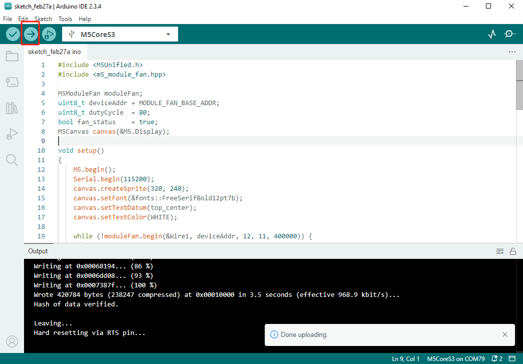
// vim: ts=4:sw=4:tw=80:et4. 编译上传
下载模式:不同设备进行程序烧录前需要进入下载模式,不同的主控设备该步骤可能有所不同。详情可参考Arduino IDE上手教程页面底部的设备程序下载教程列表,查看具体的操作方式。
CoreS3 长按复位按键 (大约 2 秒) 直到内部绿色 LED 灯亮起,便可松开,此时设备已进入下载模式,等待烧录。
.gif)
- 选中设备端口,点击 Arduino IDE 左上角编译上传按钮,等待程序完成编译并上传至设备。
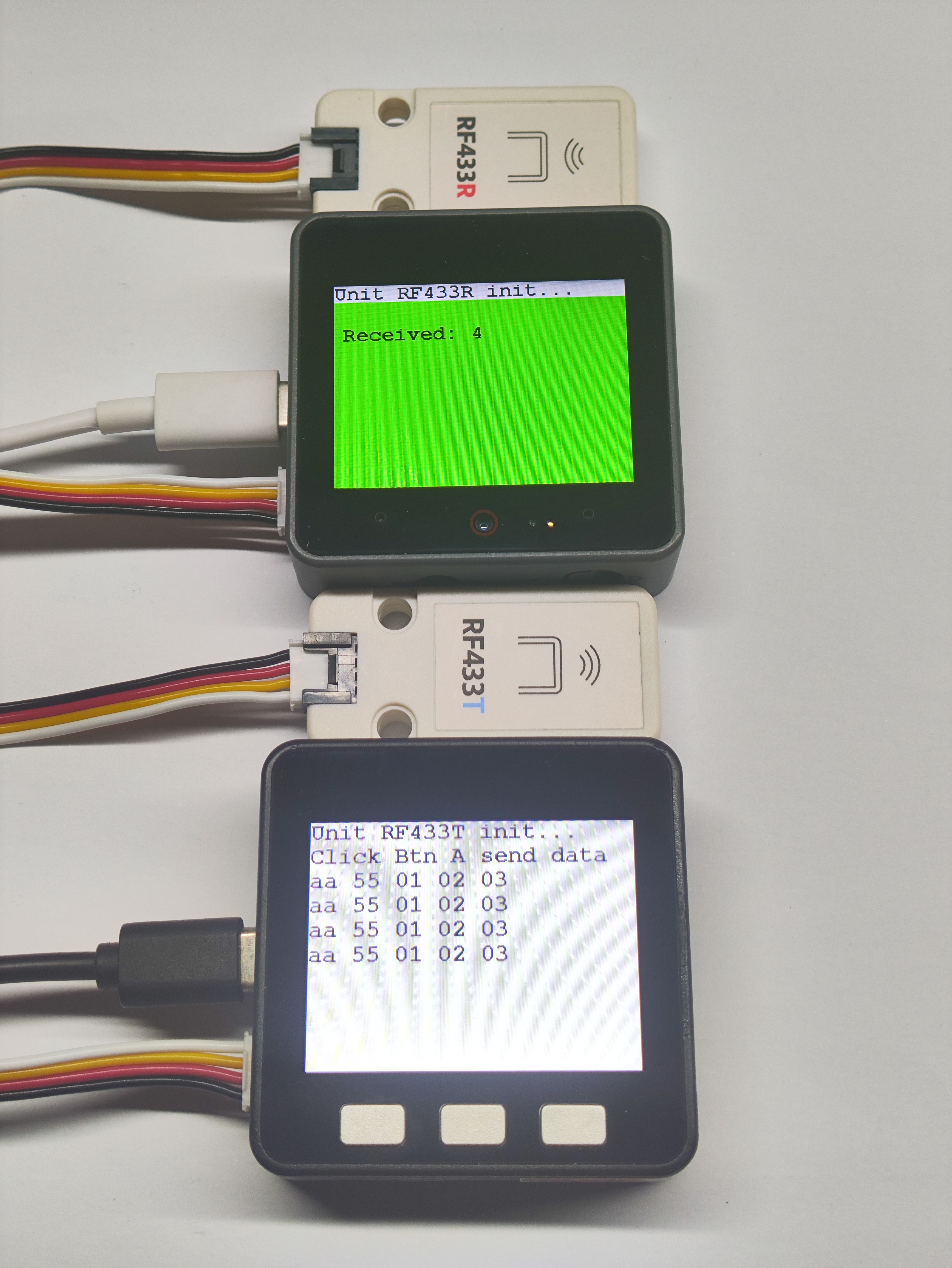
5. 通信测试
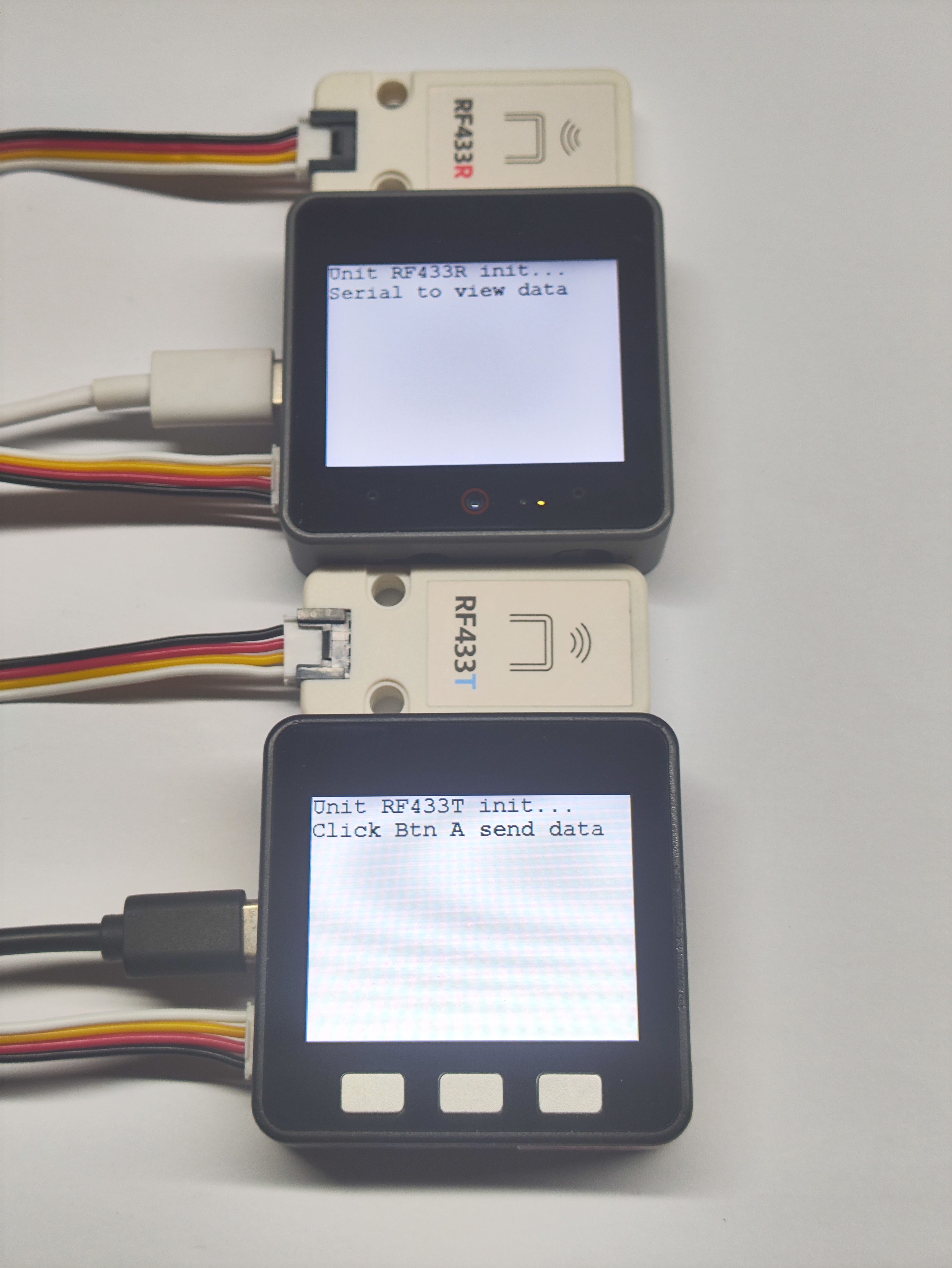
- Basic v2.7 按钮 A 按下后会通过 RF433T 发送数据包,CoreS3 通过 RF443R 接收到数据包的情况下会通过串口打印出来并实时在屏幕上显示。
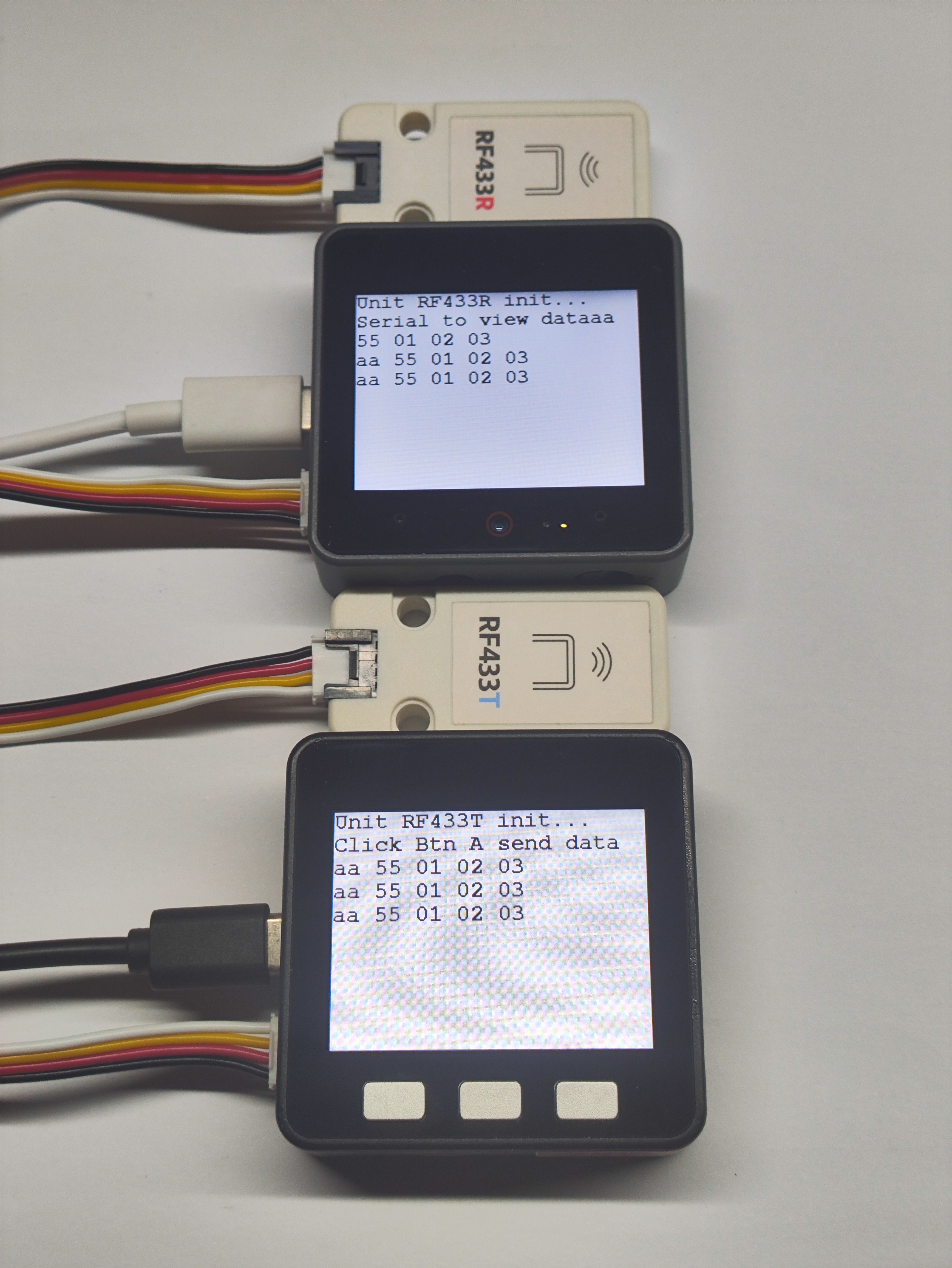
- 当双机通讯成功四次时,CoreS3 屏幕会显示绿色以示成功。