


Arduino 上手教程
2. 设备开发 & 案例程序
3. M5Unified
4. M5GFX
5. 拓展模块
Unit
Atomic
Base
IoT
Unit MIC Arduino 使用教程
1. 准备工作
环境配置: 参考 Arduino IDE 上手教程完成 IDE 安装,并根据实际使用的开发板安装对应的板管理,与需要的驱动库。
使用到的驱动库:
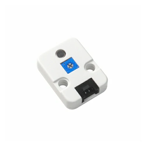
使用到的硬件产品:
2. 注意事项
引脚兼容性
由于每款主机的引脚配置不同,为了让用户更方便地使用,M5Stack 官方提供了引脚兼容性表,方便用户查看,请根据实际引脚连接情况修改案例程序。
3. 案例程序
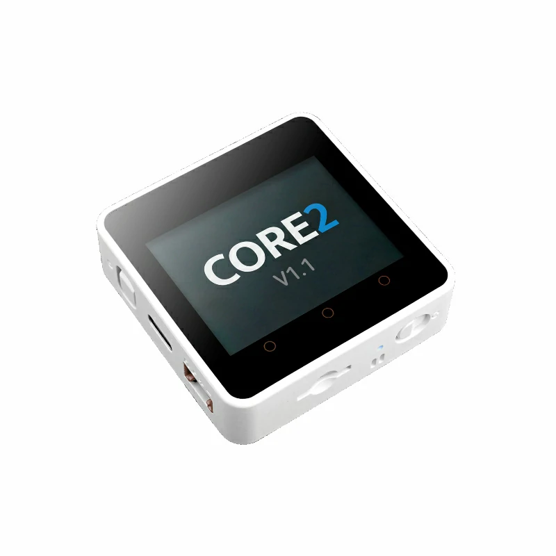
本教程中使用的主控设备为 Core2 v1.1 ,搭配 Unit MIC。请根据实际的电路连接修改程序中的引脚定义,设备连接后对应的引脚为 G33 (AIN),G32 (DIN)。
cpp
1 2 3 4 5 6 7 8 9 10 11 12 13 14 15 16 17 18 19 20 21 22 23 24 25 26 27 28 29 30 31 32 33 34 35 36 37 38 39 40 41 42 43 44 45 46 47 48 49 50 51 52 53 54 55 56 57 58 59 60 61 62 63 64 65 66 67 68 69 70 71 72 73 74 75 76 77 78 79 80 81 82 83 84 85 86 87 88 89 90 91 92 93 94 95 96 97 98 99 100 101
#include <M5Unified.h>
#include <M5GFX.h>

// Input pins
#define AIN_PIN 33      // Analog input pin
#define DIN_PIN 32      // Digital input pin (ADC)
#define LCD_W 320
#define LCD_H 240
#define MAX_LEN LCD_W   // Buffer length (matches screen width)
#define X_OFFSET 0

#define Y_AIN_OFFSET 60   // Vertical offset for AIN waveform
#define Y_DIN_OFFSET 150  // Vertical offset for DIN waveform
#define X_SCALE 1         // Amplitude scaling factor

// Draw real-time waveforms and values for AIN and DIN channels
static void draw_waveform_dual() {
  static int16_t ain_buf[MAX_LEN] = {0};  // Buffer for AIN samples
  static int16_t din_buf[MAX_LEN] = {0};  // Buffer for DIN samples
  static int16_t pt = MAX_LEN - 1;        // Circular buffer pointer

  int ainValue = analogRead(AIN_PIN);     // Read AIN ADC value
  int dinValue = analogRead(DIN_PIN);     // Read DIN ADC value

  // Map AIN: higher ADC values produce higher positions
  ain_buf[pt] = map((int16_t)(ainValue * X_SCALE), 1800, 4095, 0, 80);

  // Map DIN: ADC=0 at waveform bottom, ADC=4095 at waveform top
  din_buf[pt] = map((int16_t)(dinValue * X_SCALE), 0, 4095, 80, 0);

  if (--pt < 0) pt = MAX_LEN - 1;         // Circular buffer wrap-around

  for (int i = 1; i < MAX_LEN; i++) {
    uint16_t now_pt = (pt + i) % MAX_LEN;

    // Erase previous AIN waveform points
    M5.Lcd.drawLine(
      i + X_OFFSET,
      ain_buf[(now_pt + 1) % MAX_LEN] + Y_AIN_OFFSET,
      i + 1 + X_OFFSET,
      ain_buf[(now_pt + 2) % MAX_LEN] + Y_AIN_OFFSET,
      TFT_BLACK);

    // Erase previous DIN waveform points
    M5.Lcd.drawLine(
      i + X_OFFSET,
      din_buf[(now_pt + 1) % MAX_LEN] + Y_DIN_OFFSET,
      i + 1 + X_OFFSET,
      din_buf[(now_pt + 2) % MAX_LEN] + Y_DIN_OFFSET,
      TFT_BLACK);

    if (i < MAX_LEN - 1) {
      // Draw current AIN waveform in green
      M5.Lcd.drawLine(
        i + X_OFFSET,
        ain_buf[now_pt] + Y_AIN_OFFSET,
        i + 1 + X_OFFSET,
        ain_buf[(now_pt + 1) % MAX_LEN] + Y_AIN_OFFSET,
        TFT_GREEN);

      // Draw current DIN waveform in cyan
      M5.Lcd.drawLine(
        i + X_OFFSET,
        din_buf[now_pt] + Y_DIN_OFFSET,
        i + 1 + X_OFFSET,
        din_buf[(now_pt + 1) % MAX_LEN] + Y_DIN_OFFSET,
        TFT_CYAN);
    }
  }

  // Display current AIN ADC value (upper area)
  M5.Lcd.fillRect(10, Y_AIN_OFFSET - 25, 100, 20, TFT_BLACK);
  M5.Lcd.setTextColor(TFT_GREEN, TFT_BLACK);
  M5.Lcd.setTextFont(&fonts::FreeMonoBold9pt7b);
  M5.Lcd.setTextDatum(TL_DATUM);
  M5.Lcd.drawString("AIN: " + String(ainValue), 10, Y_AIN_OFFSET - 24);

  // Display current DIN ADC value (lower area)
  M5.Lcd.fillRect(10, Y_DIN_OFFSET + 80 - 25, 100, 20, TFT_BLACK);
  M5.Lcd.setTextColor(TFT_CYAN, TFT_BLACK);
  M5.Lcd.drawString("DIN: " + String(dinValue), 10, Y_DIN_OFFSET + 80 - 24);
}

void setup() {
  M5.begin();
  M5.Lcd.setTextFont(&fonts::FreeMonoBold9pt7b);
  M5.Lcd.setTextDatum(top_center);

  // AIN waveform label
  M5.Lcd.setTextColor(TFT_GREEN, TFT_BLACK);
  M5.Lcd.setTextDatum(top_center);
  M5.Lcd.drawString("AIN Wave", 220, Y_AIN_OFFSET - 24);

  // DIN waveform label (near bottom)
  M5.Lcd.setTextColor(TFT_CYAN, TFT_BLACK);
  M5.Lcd.drawString("DIN Wave", 220, Y_DIN_OFFSET + 80 - 24);
}

void loop() {
  draw_waveform_dual();
}4. 编译上传
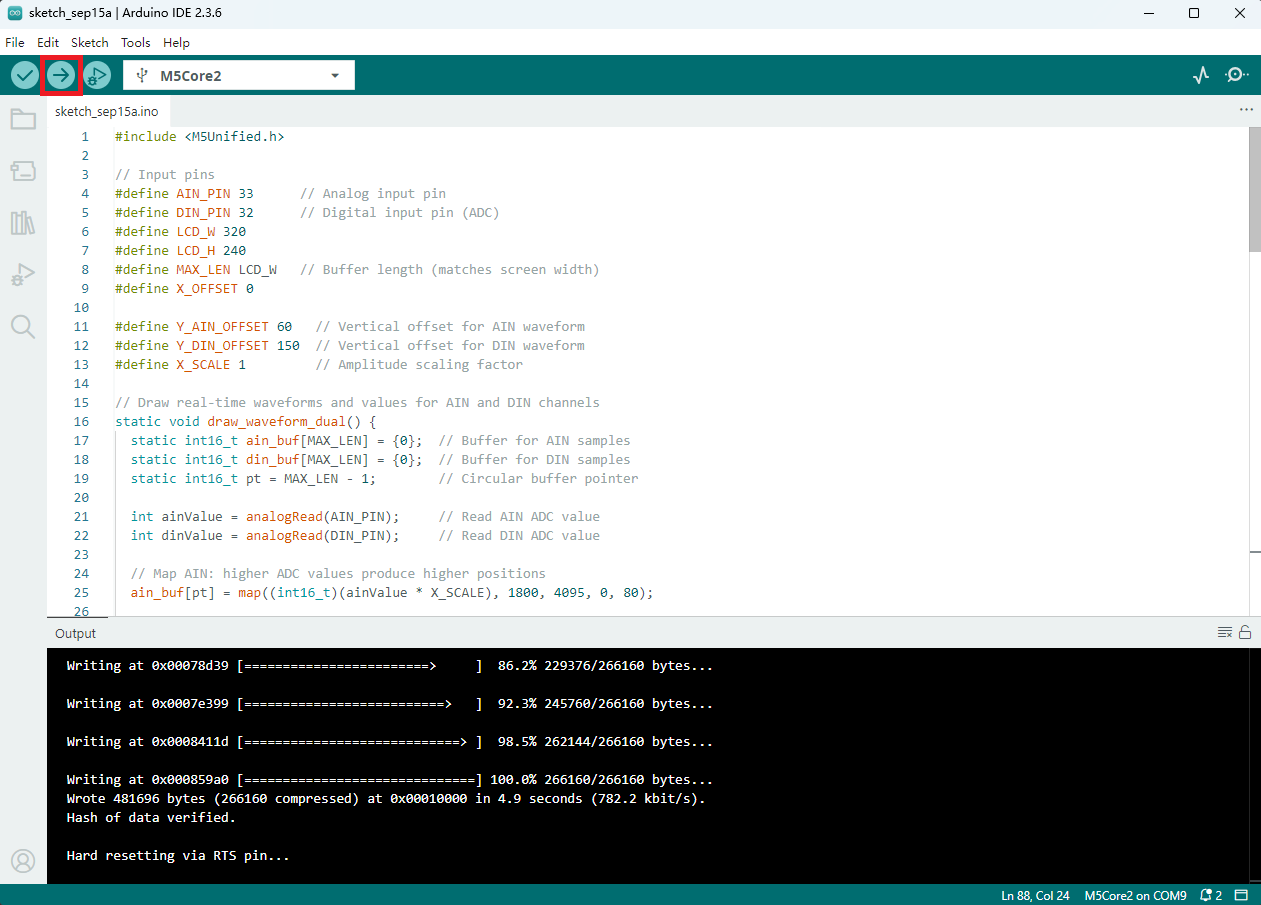
- 选中设备端口(详情请参考 程序编译与烧录),点击 Arduino IDE 左上角编译上传按钮,等待程序完成编译并上传至设备。
5. 麦克风功能效果展示
- 该例程效果为实时绘制音频波形和采集到的 ADC 值,主控设备显示如下图所示。
