Arduino 上手教程
2. 设备开发 & 案例程序
StackChan
3. M5Unified
4. M5GFX
5. 拓展模块
Unit
Atomic
Base
IoT
Atomic Audio-3.5 Base Arduino 使用教程
1. 准备工作
1. 环境配置: 参考Arduino IDE上手教程完成 IDE 安装,并根据实际使用的开发板安装对应的板管理,与需要的驱动库。
2. 使用到的驱动库:
3. 使用到的硬件产品:
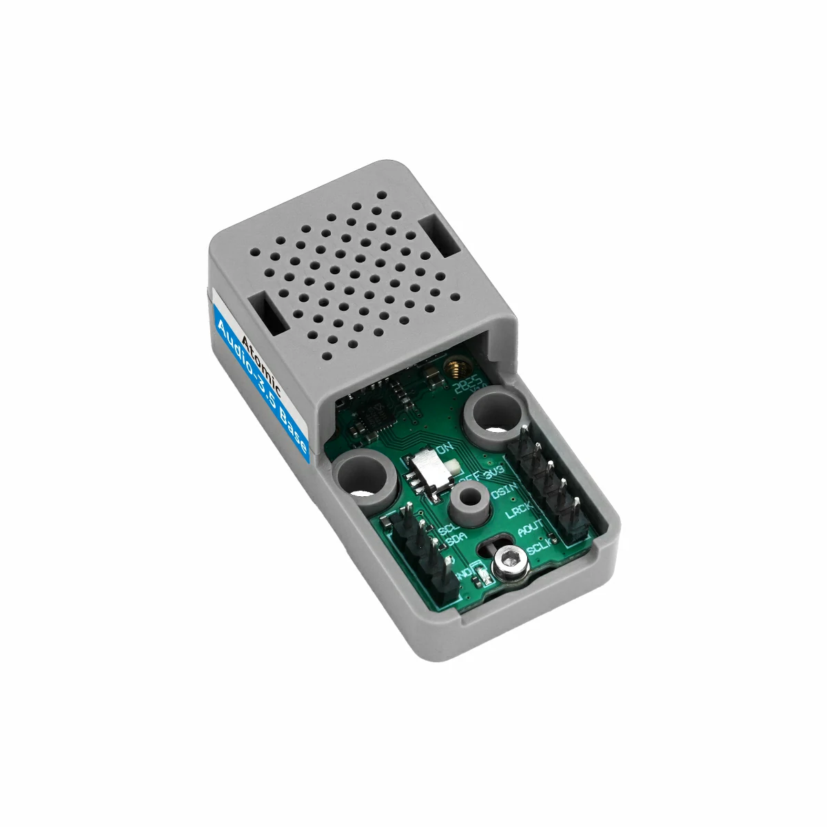
2. 麦克风切换开关
Atomic Audio-3.5 Base 上的麦克风切换开关位于下图所示位置,用于切换麦克风输入通道以适应不同应用场景需求。
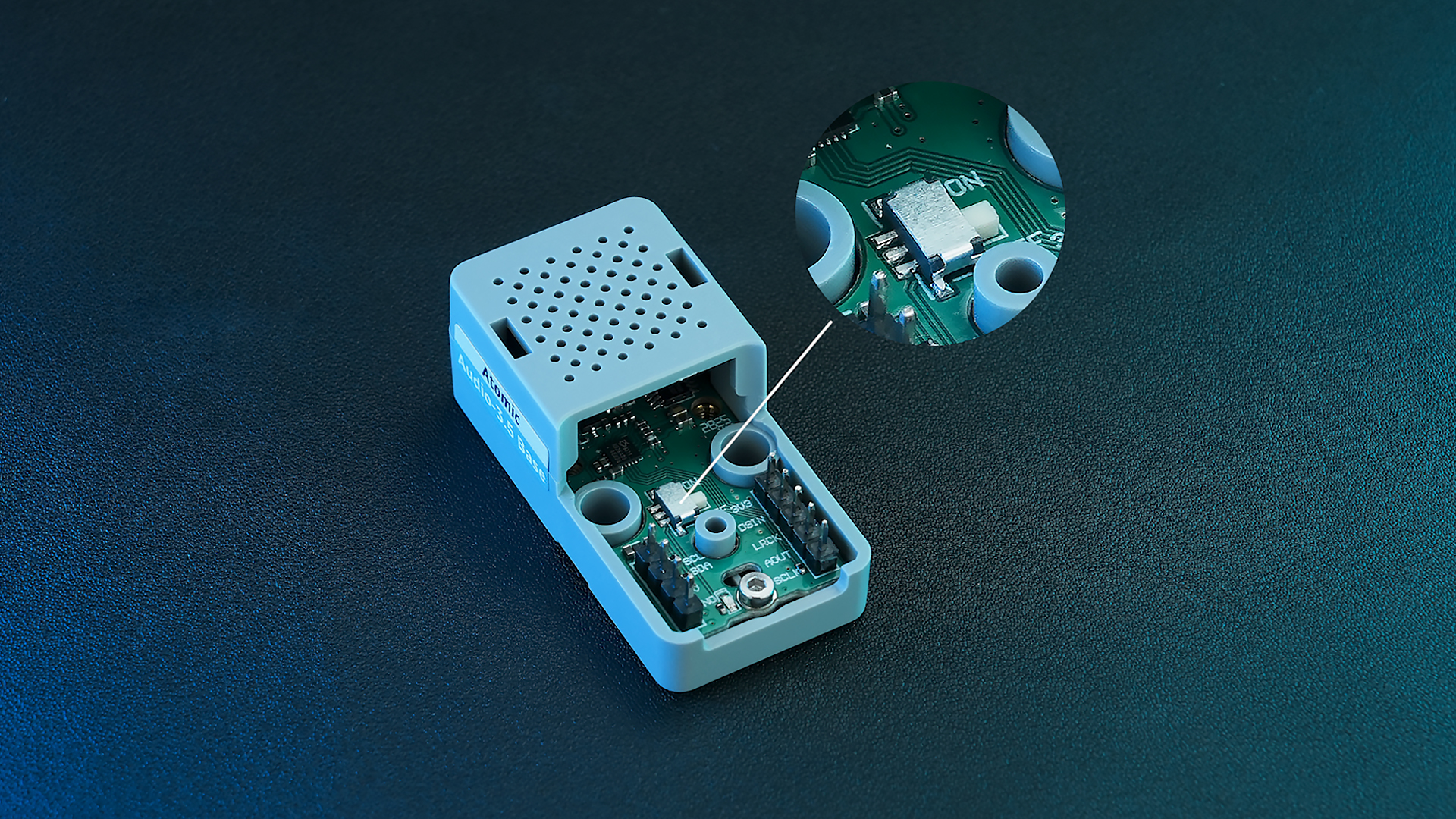
该开关有两个位置:
- ON: 保持板载麦克风供电, 外接音箱时继续使用内置麦克风
- OFF: 3.5mm 接口接入外设时,自动切换至外置麦克风,适合外接耳机场景
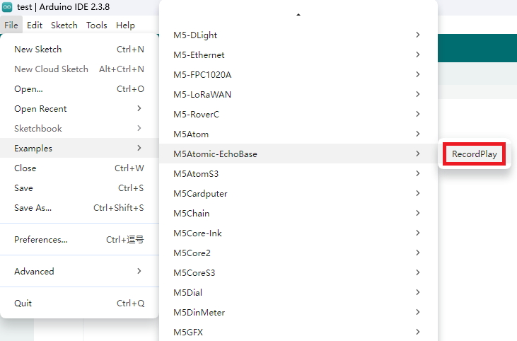
3. 案例程序
参考 M5Atomic-EchoBase 中的 RecordPlay 案例程序。根据实际连接的设备,在程序中修改实际使用的 IO 信息。本教程中使用的主控设备为 AtomS3R, 使用的 IO 配置与 AtomS3 一致。
注意事项
Atomic Audio-3.5 Base 麦克风支持的采样率范围为 16KHz-64KHz, 初始化时需要配置有效的范围内。
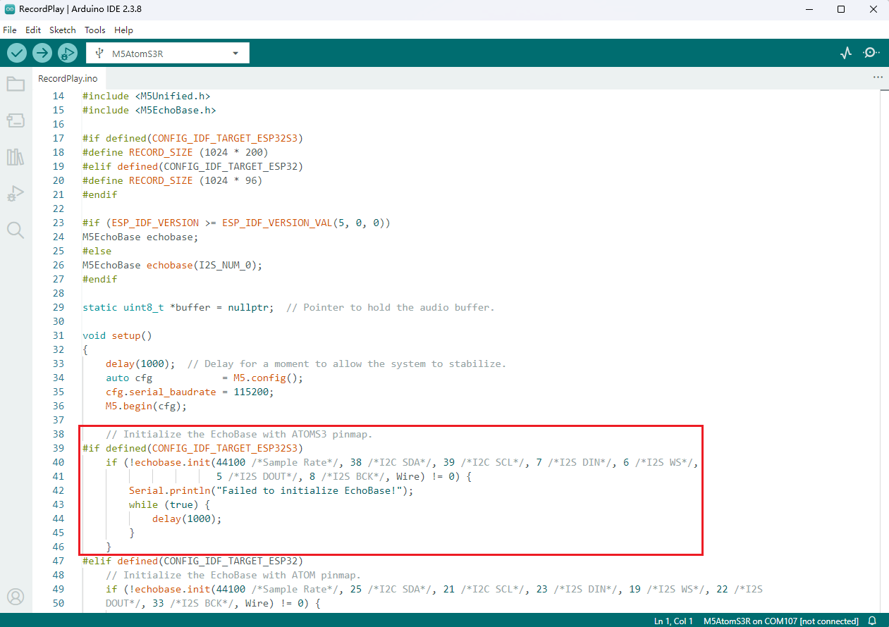
3.1 初始化
cpp
1 2 3 4 5 6
// Initialize the EchoBase with ATOMS3 pinmap.
echobase.init(44100 /*Sample Rate*/, 38 /*I2C SDA*/, 39 /*I2C SCL*/, 7 /*I2S DIN*/, 6 /*I2S WS*/,
                       5 /*I2S DOUT*/, 8 /*I2S BCK*/, Wire);

echobase.setSpeakerVolume(50);             // Set speaker volume to 50%.
echobase.setMicGain(ES8311_MIC_GAIN_6DB); // Set microphone gain to 6dB.3.2 录制与播放
cpp
1 2 3 4 5 6 7 8 9 10 11
// Recording
echobase.setMute(true);
delay(10);
echobase.record(buffer, RECORD_SIZE);  // Record audio into buffer.
delay(100);

// Playing
echobase.setMute(false);
delay(10);
echobase.play(buffer, RECORD_SIZE);  // Play audio from buffer.
delay(100);3.3 完整程序
基于 M5Unified 和 M5GFX 添加基本的显示和按键操作,实现按下按键,开始录制,完成后自动播放录音。
cpp
1 2 3 4 5 6 7 8 9 10 11 12 13 14 15 16 17 18 19 20 21 22 23 24 25 26 27 28 29 30 31 32 33 34 35 36 37 38 39 40 41 42 43 44 45 46 47 48 49 50 51 52 53 54 55 56 57 58 59 60 61 62 63 64 65 66 67 68 69 70 71 72 73 74 75 76 77 78 79 80 81 82 83 84 85 86
#include "M5Unified.h"
#include "M5EchoBase.h"
#if defined(CONFIG_IDF_TARGET_ESP32S3)
#define RECORD_SIZE (1024 * 200)
#elif defined(CONFIG_IDF_TARGET_ESP32)
#define RECORD_SIZE (1024 * 96)
#endif
// Create an instance of the M5EchoBase class
#if (ESP_IDF_VERSION >= ESP_IDF_VERSION_VAL(5, 0, 0))
M5EchoBase echobase;
#else
M5EchoBase echobase(I2S_NUM_0);
#endif
static uint8_t *buffer = nullptr; // Pointer to hold the audio buffer.
void setup()
{
M5.begin();
M5.Display.setFont(&fonts::FreeMonoBold9pt7b);
Serial.begin(115200);
#if defined(CONFIG_IDF_TARGET_ESP32S3)
// Initialize the EchoBase with ATOMS3 pinmap.
if (!echobase.init(44100 /*Sample Rate*/, 38 /*I2C SDA*/, 39 /*I2C SCL*/, 7 /*I2S DIN*/, 6 /*I2S WS*/,
5 /*I2S DOUT*/, 8 /*I2S BCK*/, Wire) != 0) {
Serial.println("Failed to initialize EchoBase!");
while (true) {
delay(1000);
}
}
#elif defined(CONFIG_IDF_TARGET_ESP32)
// Initialize the EchoBase with ATOM pinmap.
if (!echobase.init(44100 /*Sample Rate*/, 25 /*I2C SDA*/, 21 /*I2C SCL*/, 23 /*I2S DIN*/, 19 /*I2S WS*/, 22 /*I2S
DOUT*/, 33 /*I2S BCK*/, Wire) != 0) {
Serial.println("Failed to initialize EchoBase!");
while (true) {
delay(1000);
}
}
#endif
echobase.setSpeakerVolume(50); // Set speaker volume to 50%.
echobase.setMicGain(ES8311_MIC_GAIN_6DB); // Set microphone gain to 6dB.
buffer = (uint8_t *)malloc(RECORD_SIZE); // Allocate memory for the record buffer.
// Check if memory allocation was successful.
if (buffer == nullptr) {
// If memory allocation fails, enter an infinite loop.
while (true) {
Serial.println("Failed to allocate memory :(");
delay(1000);
}
}
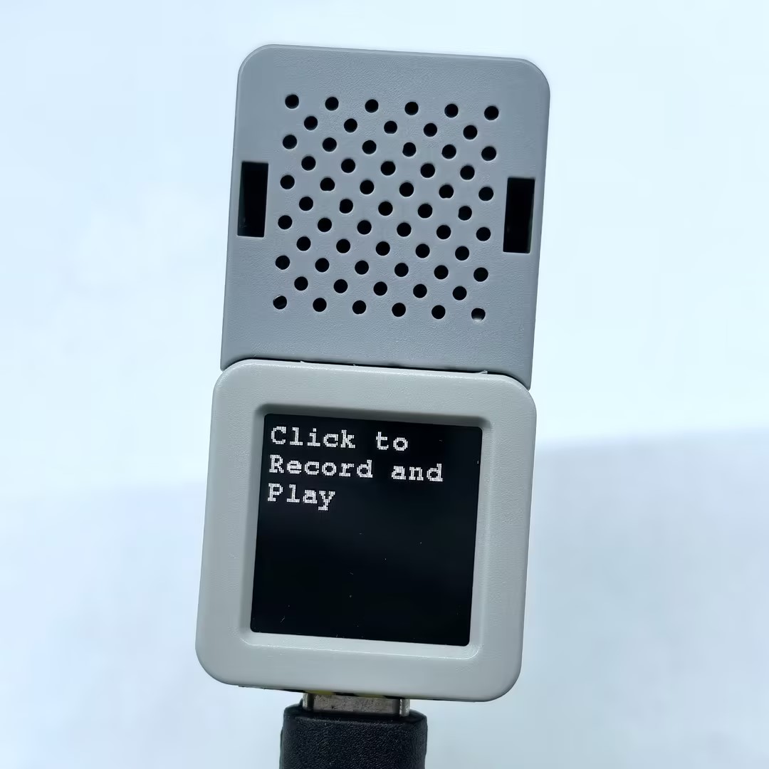
Serial.println("Device ready, start recording and playing!");
M5.Display.println("Click to \nRecord and Play");
}
void loop()
{
M5.update();
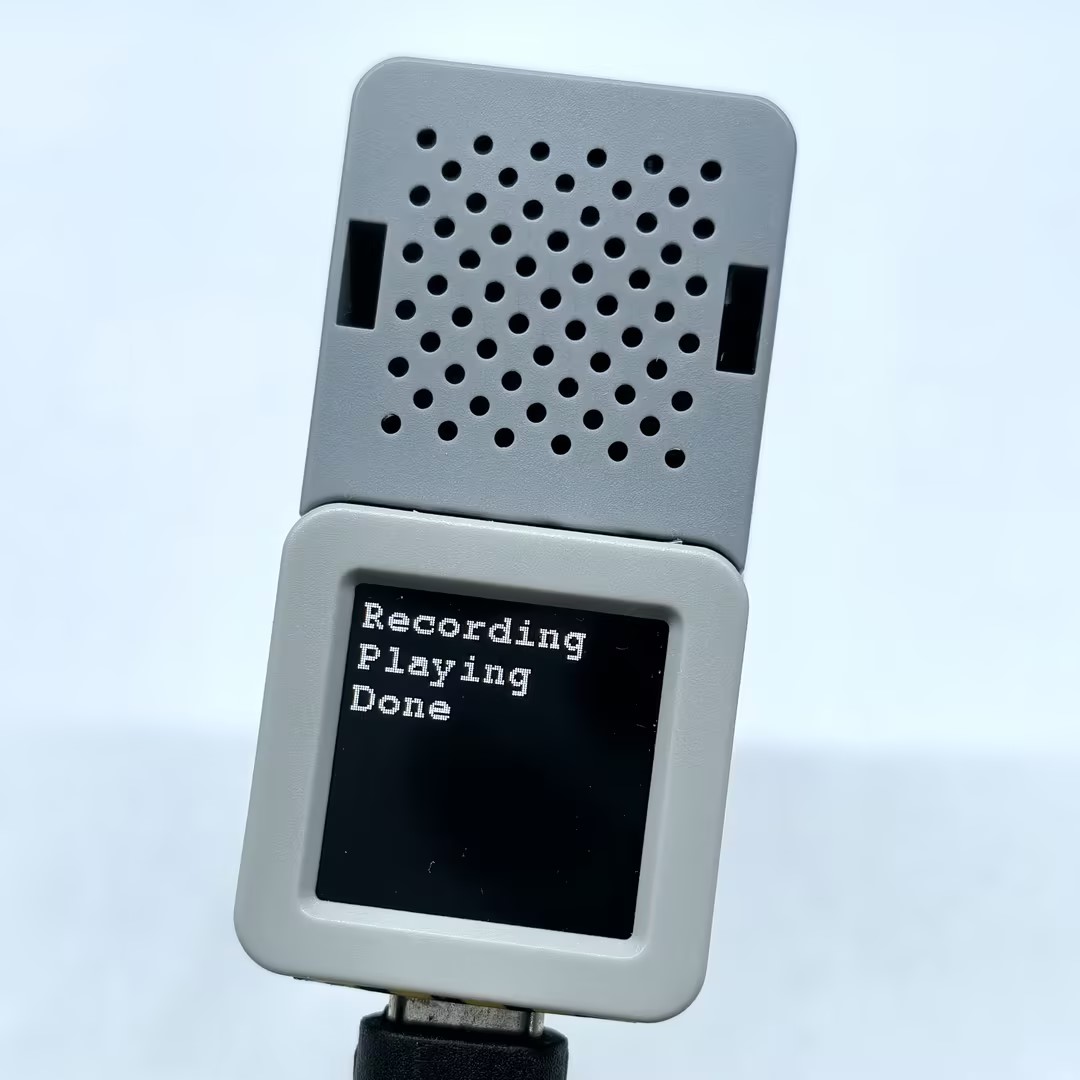
if (M5.BtnA.wasClicked()) {
M5.Display.fillScreen(BLACK);
M5.Display.setCursor(0, 0);
M5.Display.println("Recording");
Serial.println("Start recording...");
// Recording
echobase.setMute(true);
delay(10);
echobase.record(buffer, RECORD_SIZE); // Record audio into buffer.
delay(100);
M5.Display.println("Playing");
Serial.println("Start playing...");
// Playing
echobase.setMute(false);
delay(10);
echobase.play(buffer, RECORD_SIZE); // Play audio from buffer.
delay(100);
M5.Display.println("Done");
Serial.println("Done");
}
}4. 编译上传
1. 下载模式:不同设备进行程序烧录前需要下载模式,不同的主控设备该步骤可能有所不同。详情可参考Arduino IDE上手教程页面底部的设备程序下载教程列表,查看具体的操作方式。
AtomS3R 长按复位按键 (大约 2 秒) 直到内部绿色 LED 灯亮起,便可松开,此时设备已进入下载模式,等待烧录。
- 2. 选中设备端口,点击 Arduino IDE 左上角编译上传按钮,等待程序完成编译并上传至设备。
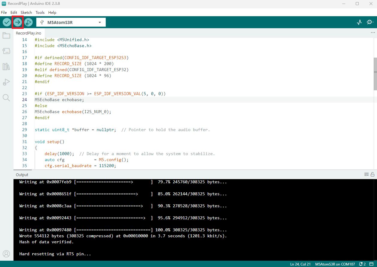
5. 录制与播放