


Arduino 上手教程
2. 设备开发 & 案例程序
StackChan
3. M5Unified
4. M5GFX
5. 拓展模块
Unit
Atomic
Base
IoT
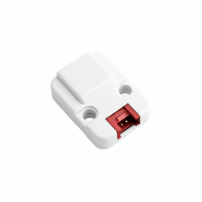
Unit EXT.IO2 Arduino 使用教程
1.准备工作
1.环境配置: 参考Arduino IDE上手教程完成IDE安装, 并根据实际使用的开发板安装对应的板管理, 与需要的驱动库。
2.使用到的驱动库:
3.使用到的硬件产品:

2.案例程序
案例说明
Unit EXT.IO2 是一款 8 路 IO 拓展单元。每路 IO 支持独立配置数字输入/输出,ADC,Servo 控制,RGB LED 控制模式。参考以下案例,实现不同的控制功能。
Digital Input Mode
cpp
1 2 3 4 5 6 7 8 9 10 11 12 13 14 15 16 17 18 19 20 21 22 23 24 25 26 27 28 29 30 31 32
#include <M5Unified.h>
#include "M5_EXTIO2.h"

M5_EXTIO2 extio;

void setup()
{
    M5.begin();
    // begin(TwoWire *wire, uint8_t sda, uint8_t scl, uint8_t addr)
    while (!extio.begin(&Wire, 2, 1, 0x45)) {
        Serial.println("Unit EXT.IO2 Init Fail");
        M5.Display.println("Unit EXT.IO2 Init Fail");
        delay(1000);
    }

    M5.Display.clear();
    M5.Display.setColorDepth(1);
    M5.Display.setFont(&fonts::Orbitron_Light_32);
    M5.Display.setTextDatum(middle_center);
    extio.setAllPinMode(DIGITAL_INPUT_MODE);
}

void loop()
{
    M5.Display.clear();
    M5.Display.setCursor(0, 0);
    for (uint8_t i = 0; i < 8; i++) {
        bool status = extio.getDigitalInput(i);
        M5.Display.printf("CH[%d]: %d\r\n", i, status ? "HIGH" : "LOW");
    }
    delay(100);
}Digital Output Mode
cpp
1 2 3 4 5 6 7 8 9 10 11 12 13 14 15 16 17 18 19 20 21 22 23 24 25 26 27 28 29 30 31 32 33 34
#include <M5Unified.h>
#include "M5_EXTIO2.h"

M5_EXTIO2 extio;
bool output_level = LOW;

void setup()
{
    M5.begin();
    // begin(TwoWire *wire, uint8_t sda, uint8_t scl, uint8_t addr)
    while (!extio.begin(&Wire, 2, 1, 0x45)) {
        Serial.println("Unit EXT.IO2 Init Fail");
        M5.Display.println("Unit EXT.IO2 Init Fail");
        delay(1000);
    }

    M5.Display.clear();
    M5.Display.setColorDepth(1);
    M5.Display.setFont(&fonts::Orbitron_Light_32);
    M5.Display.setTextDatum(middle_center);
    extio.setAllPinMode(DIGITAL_OUTPUT_MODE);
}

void loop()
{
    output_level = !output_level;
    M5.Display.clear();
    M5.Display.setCursor(0, 0);
    for (uint8_t i = 0; i < 8; i++) {
        extio.setDigitalOutput(i, output_level);
        M5.Display.printf("CH[%d]: %d\r\n", i, output_level ? "HIGH" : "LOW");
        delay(200);
    }
}ADC Input Mode
cpp
1 2 3 4 5 6 7 8 9 10 11 12 13 14 15 16 17 18 19 20 21 22 23 24 25 26 27 28 29 30 31 32 33
#include <M5Unified.h>
#include "M5_EXTIO2.h"

M5_EXTIO2 extio;

void setup()
{
    M5.begin();
    // begin(TwoWire *wire, uint8_t sda, uint8_t scl, uint8_t addr)
    while (!extio.begin(&Wire, 2, 1, 0x45)) {
        Serial.println("Unit EXT.IO2 Init Fail");
        M5.Display.println("Unit EXT.IO2 Init Fail");
        delay(1000);
    }

    M5.Display.clear();
    M5.Display.setColorDepth(1);
    M5.Display.setFont(&fonts::Orbitron_Light_32);
    M5.Display.setTextDatum(middle_center);
    extio.setAllPinMode(ADC_INPUT_MODE);
}

void loop()
{
    M5.Display.clear();
    M5.Display.setCursor(0, 0);
    for (uint8_t i = 0; i < 8; i++) {
        uint16_t adc = extio.getAnalogInput(i, _12bit);  // Get ADC value. 获取ADC值
        M5.Display.printf("CH:%d ADC: %d\r\n", i, adc);
    }

    delay(200);
}Servo Control Mode
cpp
1 2 3 4 5 6 7 8 9 10 11 12 13 14 15 16 17 18 19 20 21 22 23 24 25 26 27 28 29 30 31 32 33 34 35 36 37 38 39 40 41 42 43 44
#include <M5Unified.h>
#include "M5_EXTIO2.h"

M5_EXTIO2 extio;

void setup()
{
    M5.begin();
    // begin(TwoWire *wire, uint8_t sda, uint8_t scl, uint8_t addr)
    while (!extio.begin(&Wire, 2, 1, 0x45)) {
        Serial.println("Unit EXT.IO2 Init Fail");
        M5.Display.println("Unit EXT.IO2 Init Fail");
        delay(1000);
    }

    M5.Display.clear();
    M5.Display.setColorDepth(1);
    M5.Display.setFont(&fonts::Orbitron_Light_32);
    M5.Display.setTextDatum(middle_center);
    extio.setAllPinMode(SERVO_CTL_MODE);
}

void loop()
{
    M5.Display.clear();
    M5.Display.setCursor(0, 0);
    for (uint8_t deg = 0; deg <= 180; deg += 45) {
        for (uint8_t i = 0; i < 8; i++) {
            extio.setServoAngle(i, deg);
            M5.Display.printf("CH[%d]: DEG: %d\r\n", i, deg);
            delay(200);
        }
    }
    delay(1000);
    M5.Display.clear();
    M5.Display.setCursor(0, 0);
    for (int pulse = 500; pulse <= 2500; pulse += 100) {
        for (uint8_t i = 0; i < 8; i++) {
            extio.setServoPulse(i, pulse);
            M5.Display.printf("CH:%d P: %d\r\n", i, pulse);
        }
    }
    delay(1000);
}RGB LED Control Mode
cpp
1 2 3 4 5 6 7 8 9 10 11 12 13 14 15 16 17 18 19 20 21 22 23 24 25 26 27 28 29 30 31 32 33 34 35 36 37 38 39
#include <M5Unified.h>
#include "M5_EXTIO2.h"

M5_EXTIO2 extio;

void setup()
{
    M5.begin();
    // begin(TwoWire *wire, uint8_t sda, uint8_t scl, uint8_t addr)
    while (!extio.begin(&Wire, 2, 1, 0x45)) {
        Serial.println("Unit EXT.IO2 Init Fail");
        M5.Display.println("Unit EXT.IO2 Init Fail");
        delay(1000);
    }
    extio.setAllPinMode(RGB_LED_MODE);

    M5.Display.clear();
    M5.Display.setColorDepth(1);
    M5.Display.setFont(&fonts::Orbitron_Light_32);
    M5.Display.setTextDatum(middle_center);
    M5.Display.setCursor(0, 0);
    M5.Display.println("Unit EXT.IO2 RGB LED MODE");
}

void loop()
{
    for (uint8_t i = 0; i < 8; i++) {
        extio.setLEDColor(i, 0xff0000);
    }
    delay(1000);
    for (uint8_t i = 0; i < 8; i++) {
        extio.setLEDColor(i, 0x00ff00);
    }
    delay(1000);
    for (uint8_t i = 0; i < 8; i++) {
        extio.setLEDColor(i, 0x0000ff);
    }
    delay(1000);
}3.编译上传
1.下载模式: 不同设备进行程序烧录前需要下载模式, 不同的主控设备该步骤可能有所不同。详情可参考Arduino IDE上手教程页面底部的设备程序下载教程列表, 查看具体的操作方式。
CoreS3长按复位按键(大约2秒)直到内部绿色LED灯亮起,便可松开,此时设备已进入下载模式,等待烧录。
.gif)
- 2.选中设备端口, 点击Arduino IDE左上角编译上传按钮, 等待程序完成编译并上传至设备。
4.拓展IO控制
使用数字输出模式,拓展 IO 控制多路LED灯点亮与熄灭。