

Arduino 上手教程
2. 设备开发 & 案例程序
3. M5Unified
4. M5GFX
5. 拓展模块
Unit
Atomic
Tab5
IoT
Unit Step16 Arduino 使用教程
1. 准备工作
- 环境配置: 参考 Arduino IDE 上手教程完成 IDE 安装,并根据实际使用的开发板安装对应的板管理,与需要的驱动库。
- 使用到的驱动库:
注意
需要在 GitHub 上下载最新的库版本,库地址: M5Unit-Step16 - M5Stack GitHub,请勿在 Arduino Library 中下载。(如有疑问,请参考此教程)
- 使用到的硬件产品:

2. 注意事项
引脚兼容性
由于每款主机的引脚配置不同,为了让用户更方便地使用,M5Stack 官方提供了引脚兼容性表,方便用户查看,请根据实际引脚连接情况修改案例程序。
3. 案例程序
- 本教程中使用的主控设备为 CoreS3 ,搭配 Unit Step16。本 16 定位旋转编码器模块采用 I2C 的方式通讯,根据实际的电路连接修改程序中的引脚定义,设备连接后对应的 I2C 引脚为
G1 (SCL),G2 (SDA)。
cpp
1 2 3 4 5 6 7 8 9 10 11 12 13 14 15 16 17 18 19 20 21 22 23 24 25 26 27 28 29 30 31 32 33 34 35 36 37 38 39 40 41 42 43 44 45 46 47 48 49 50 51 52 53 54 55 56 57 58 59 60 61 62 63 64 65 66 67 68 69 70 71 72 73 74 75 76 77 78 79 80 81 82 83 84 85 86 87 88 89 90 91 92 93 94 95 96 97 98 99 100 101 102 103 104 105 106 107 108 109 110 111 112 113 114 115 116 117 118 119 120 121 122 123 124 125 126 127 128 129 130 131 132 133 134 135 136 137 138 139 140 141 142 143 144 145 146
/*
 * SPDX-FileCopyrightText: 2025 M5Stack Technology CO LTD
 *
 * SPDX-License-Identifier: MIT
 */
/*
 * @Hardwares: M5Stack PortA device + Unit Step16
 * @Dependent Library:
 * M5Unit-Step16:https://github.com/m5stack/M5Unit-Step16
 * @description: When the knob is rotated, only 0-8 is displayed,
 *              when raw value reaches 9-F, rotation direction is automatically reversed,
 *              LED brightness follows display value, never zero (minimum 10%),
 *              RGB color follows the 0-8 pattern
 */
#include <M5Unified.h>
#include <M5UnitStep16.h>

#define I2C_SDA_PIN     (2)
#define I2C_SCL_PIN     (1)
#define NUM_DIGITS      (9)
#define MAX_DIGIT       (8)
#define MIN_DIGIT       (0)
#define MIN_BRIGHTNESS  (10)
#define MAX_BRIGHTNESS  (100)
#define BRIGHTNESS_STEP (10)
#define RGB_BRIGHTNESS  (70)
#define LED_ALWAYS_ON   (0xFF)

UnitStep16 step16;
uint8_t currentDigit = 0;
uint8_t lastRawValue = 0;
bool isFirstRead     = true;

const uint8_t digitBrightness[NUM_DIGITS] = {
    MIN_BRIGHTNESS,                        // 0 - 10%
    MIN_BRIGHTNESS + BRIGHTNESS_STEP,      // 1 - 20%
    MIN_BRIGHTNESS + BRIGHTNESS_STEP * 2,  // 2 - 30%
    MIN_BRIGHTNESS + BRIGHTNESS_STEP * 3,  // 3 - 40%
    MIN_BRIGHTNESS + BRIGHTNESS_STEP * 4,  // 4 - 50%
    MIN_BRIGHTNESS + BRIGHTNESS_STEP * 5,  // 5 - 60%
    MIN_BRIGHTNESS + BRIGHTNESS_STEP * 6,  // 6 - 70%
    MIN_BRIGHTNESS + BRIGHTNESS_STEP * 7,  // 7 - 80%
    MIN_BRIGHTNESS + BRIGHTNESS_STEP * 8   // 8 - 90%
};

struct MyRGBColor {
    uint8_t r, g, b;
    const char* name;
};

const MyRGBColor digitColors[NUM_DIGITS] = {
    {0, 0, 128, "Deep Blue"},       // 0 - cold color
    {0, 64, 192, "Blue"},           // 1
    {0, 128, 255, "Light Blue"},    // 2
    {0, 192, 192, "Cyan"},          // 3
    {0, 255, 128, "Cyan Green"},    // 4
    {128, 255, 0, "Yellow Green"},  // 5
    {192, 192, 0, "Yellow"},        // 6
    {255, 128, 0, "Orange"},        // 7
    {255, 64, 0, "Orange Red"}      // 8 - warm color
};

uint8_t mapRawValueToDigit(uint8_t rawValue);
void updateDisplay(uint8_t digit);
uint8_t mapRawValueToDigit(uint8_t rawValue);
void updateDisplay(uint8_t digit);
void handleValueChange(uint8_t oldVal, uint8_t newVal);

void setup()
{
    M5.begin();
    Serial.begin(115200);
    Wire.begin(I2C_SDA_PIN, I2C_SCL_PIN);
    while(!step16.begin()){
        delay(1000);
        Serial.println("M5Unit-Step16 not found!");
    }
    M5.Display.fillRect(0, 0, 320, 240, WHITE);
    M5.Display.setTextColor(BLACK);
    M5.Display.setFont(&fonts::FreeMonoBold18pt7b);
    M5.Display.setCursor(0, 0);
    M5.Display.printf("M5Unit-Step16\n");
    step16.setRgbConfig(1);
    step16.setRgbBrightness(RGB_BRIGHTNESS);
    lastRawValue = step16.getValue();
    currentDigit = mapRawValueToDigit(lastRawValue);
    updateDisplay(currentDigit);
}

void loop()
{
    uint8_t rawValue = step16.getValue();
    if (rawValue != lastRawValue && !isFirstRead) {
        handleValueChange(lastRawValue, rawValue);
        lastRawValue = rawValue;
        M5.Display.fillRect(0, 0, 320, 240, WHITE);
        M5.Display.setCursor(0, 0);
        M5.Display.printf("Raw Value: %d\n", rawValue);
    }
    if (isFirstRead)    isFirstRead = false;
    delay(50);
}

/**
 * @brief Handle value change
 * @param oldVal Old raw value
 * @param newVal New raw value
 */
void handleValueChange(uint8_t oldVal, uint8_t newVal)
{
    if (newVal >= 9 && newVal <= 15) {
        uint8_t currentDirection = step16.getSwitchState();
        step16.setSwitchState(currentDirection == 0 ? 1 : 0);
    }
    uint8_t newDigit = mapRawValueToDigit(newVal);
    if (newDigit != currentDigit) {
        currentDigit = newDigit;
        updateDisplay(currentDigit);
    }
}

/**
 * @brief Map raw value to digit 0-8
 * @param rawValue Raw value (0-15)
 * @return Mapped digit (0-8)
 */
uint8_t mapRawValueToDigit(uint8_t rawValue)
{
    if (rawValue <= 8) {
        return rawValue;
    } else {
        return 17 - rawValue;
    }
}

/**
 * @brief Update display
 * @param digit Digit to display (0-8)
 */
void updateDisplay(uint8_t digit)
{
    if (digit > MAX_DIGIT) return;
    step16.setLedBrightness(digitBrightness[digit]);
    step16.setRgb(digitColors[digit].r, digitColors[digit].g, digitColors[digit].b);
    step16.setLedConfig(LED_ALWAYS_ON);
}4. 编译上传
下载模式:设备进行程序烧录前需要进入下载模式,不同的主控设备该步骤可能有所不同。详情可参考 Arduino IDE 上手教程页面底部的设备程序下载教程列表,查看具体的操作方式。
CoreS3 长按复位按键 (大约 2 秒) 直到内部绿色 LED 灯亮起,便可松开,此时设备已进入下载模式,等待烧录。
.gif)
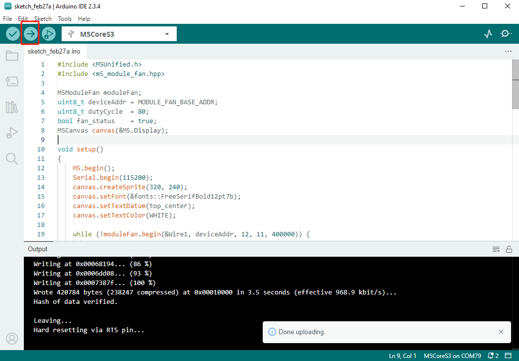
- 选中设备端口,点击 Arduino IDE 左上角编译上传按钮,等待程序完成编译并上传至设备。
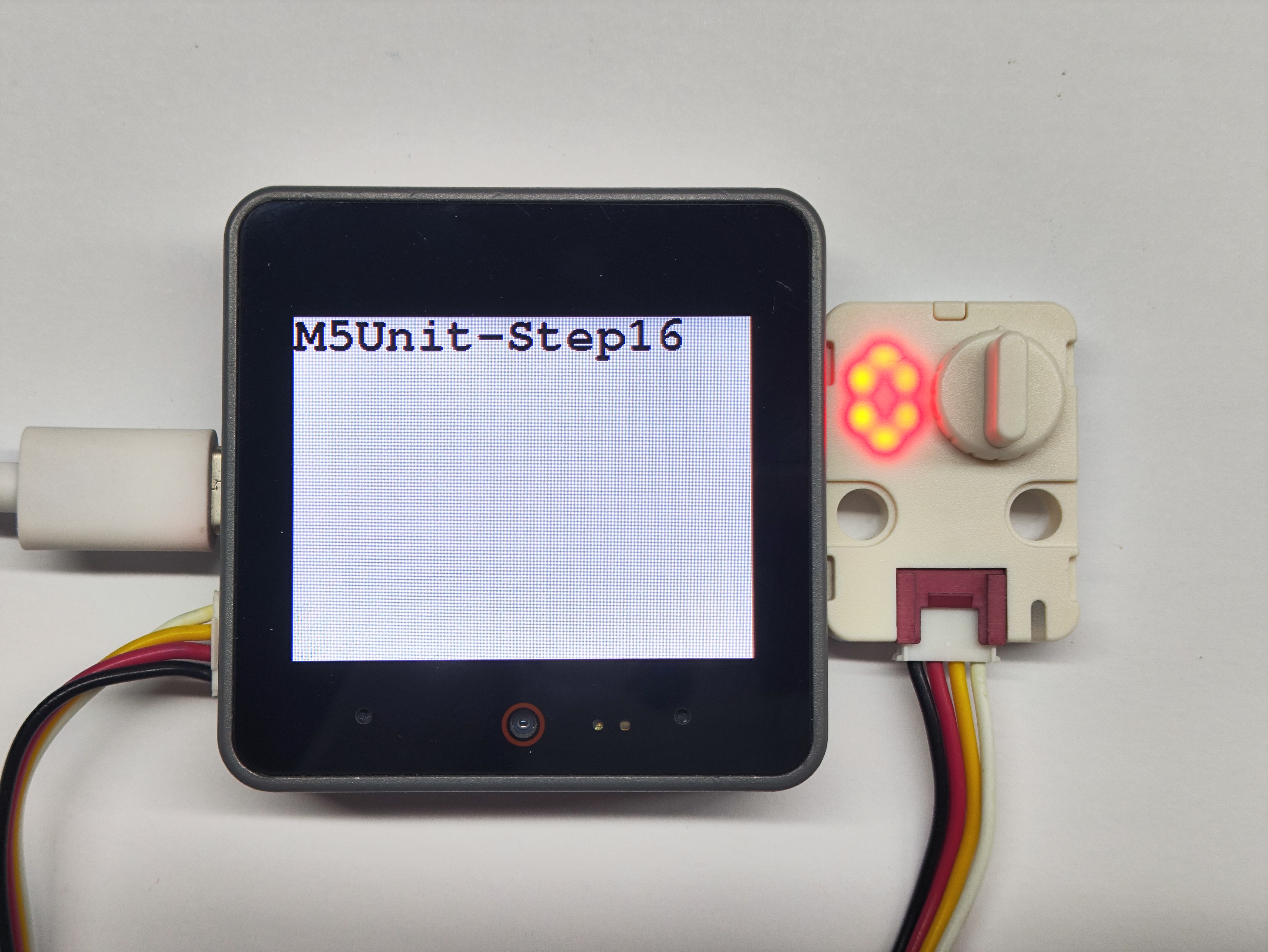
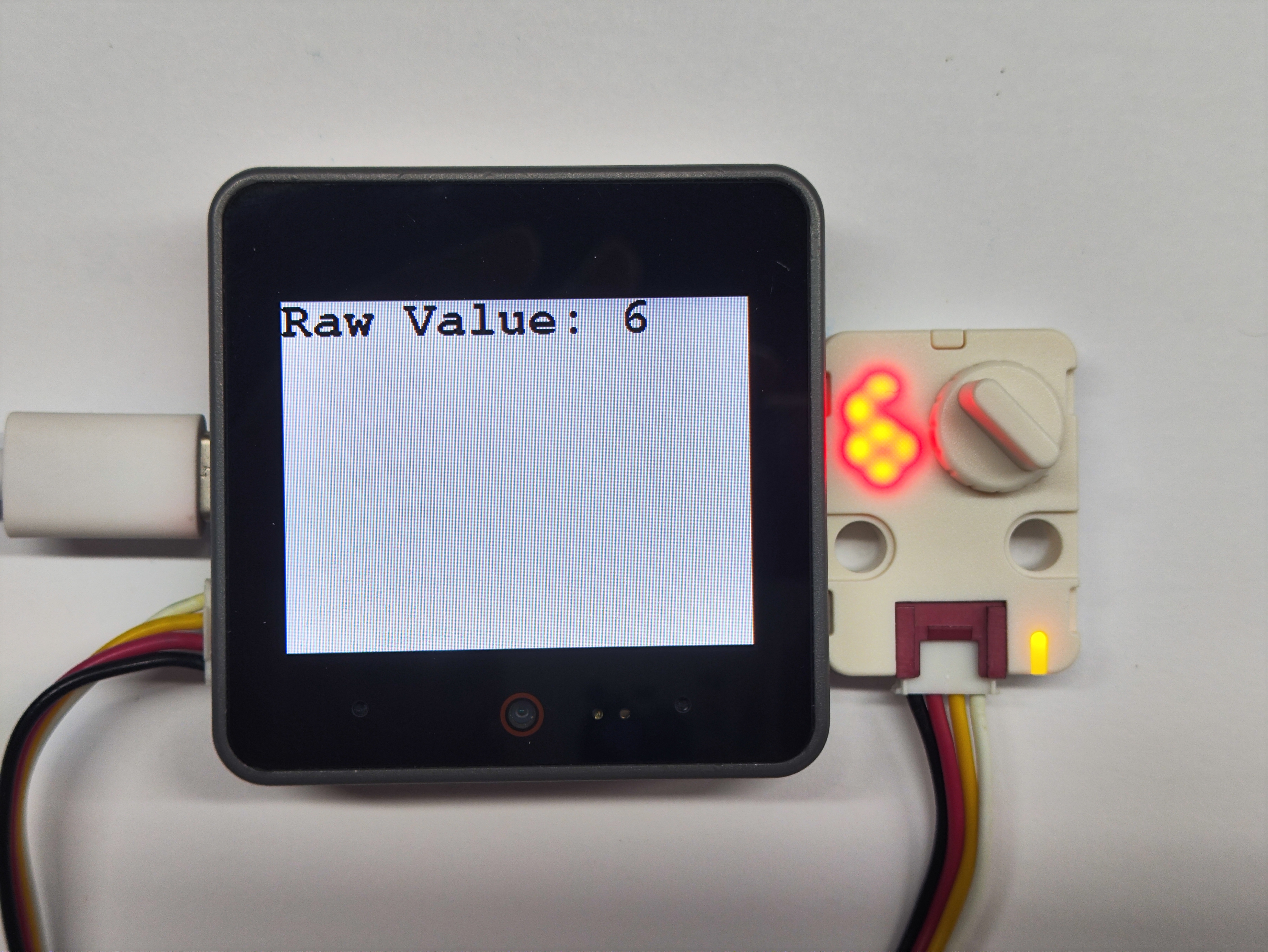
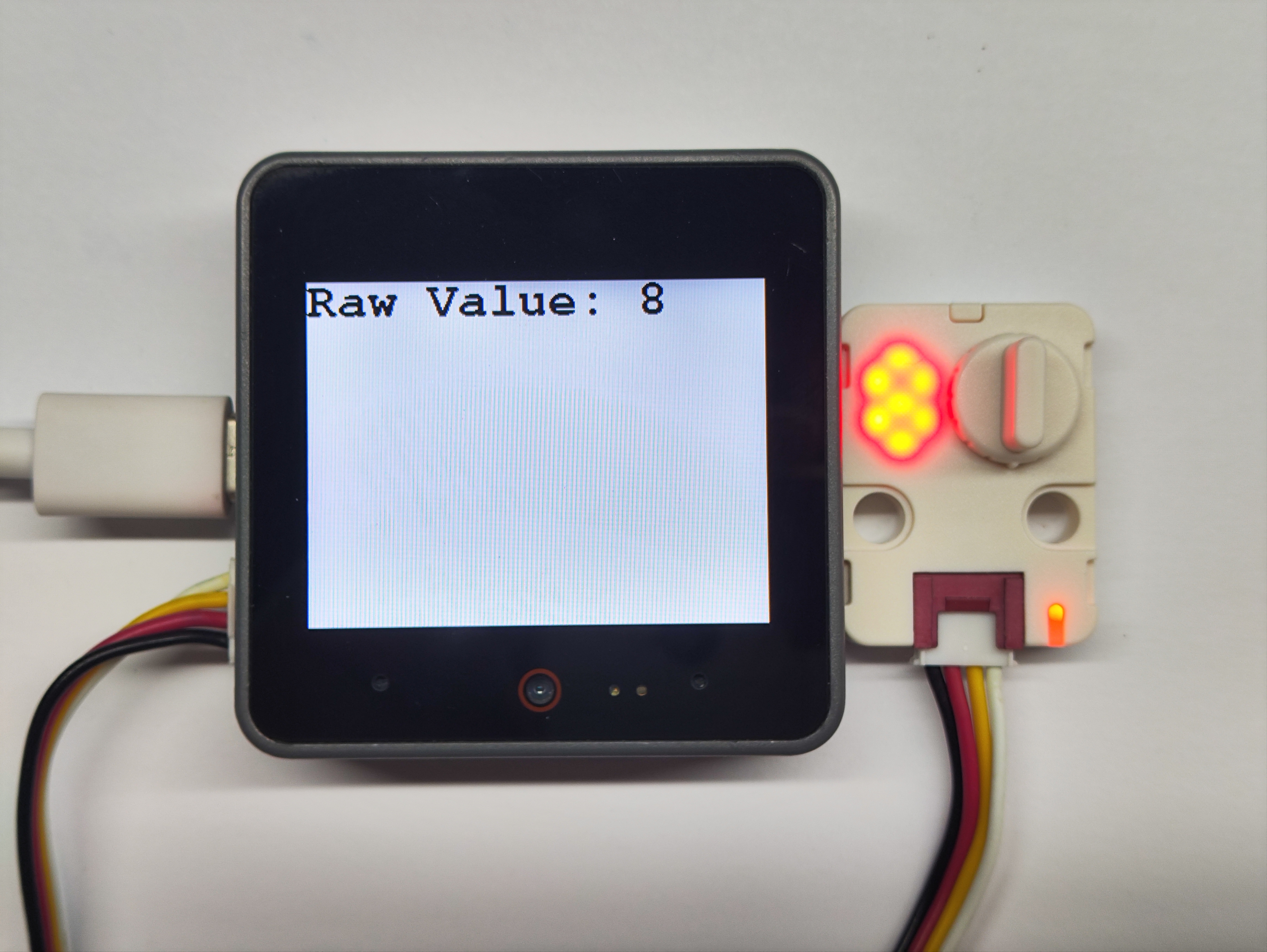
5. 数码管显示
- 程序初始状态晶体管显示为 0 ,当转动旋钮后,晶体管的数字会随着旋转而改变,RGB 灯的颜色也会随之变换。
Page Tools