Arduino Quick Start
2. Devices & Examples
3. M5Unified
4. M5GFX
5. Extensions
Unit
Atomic
Tab5
IoT
Accessories
PaperColor M5PM1 Power Management
1. Multi-Level Power Switch Design
PaperColor integrates M5PM1 internally, and combined with the hardware circuit, implements a multi-level power switch. Different power switch levels control the supply to their corresponding peripherals and interfaces. Users can switch between different power enable levels based on operational requirements, disabling unused peripheral sections to achieve system-wide low power consumption.
M5PM1 Driver Library
The M5PM1 driver library provides a convenient way to configure M5PM1 pin functions for low-power wake-up and peripheral power switching.
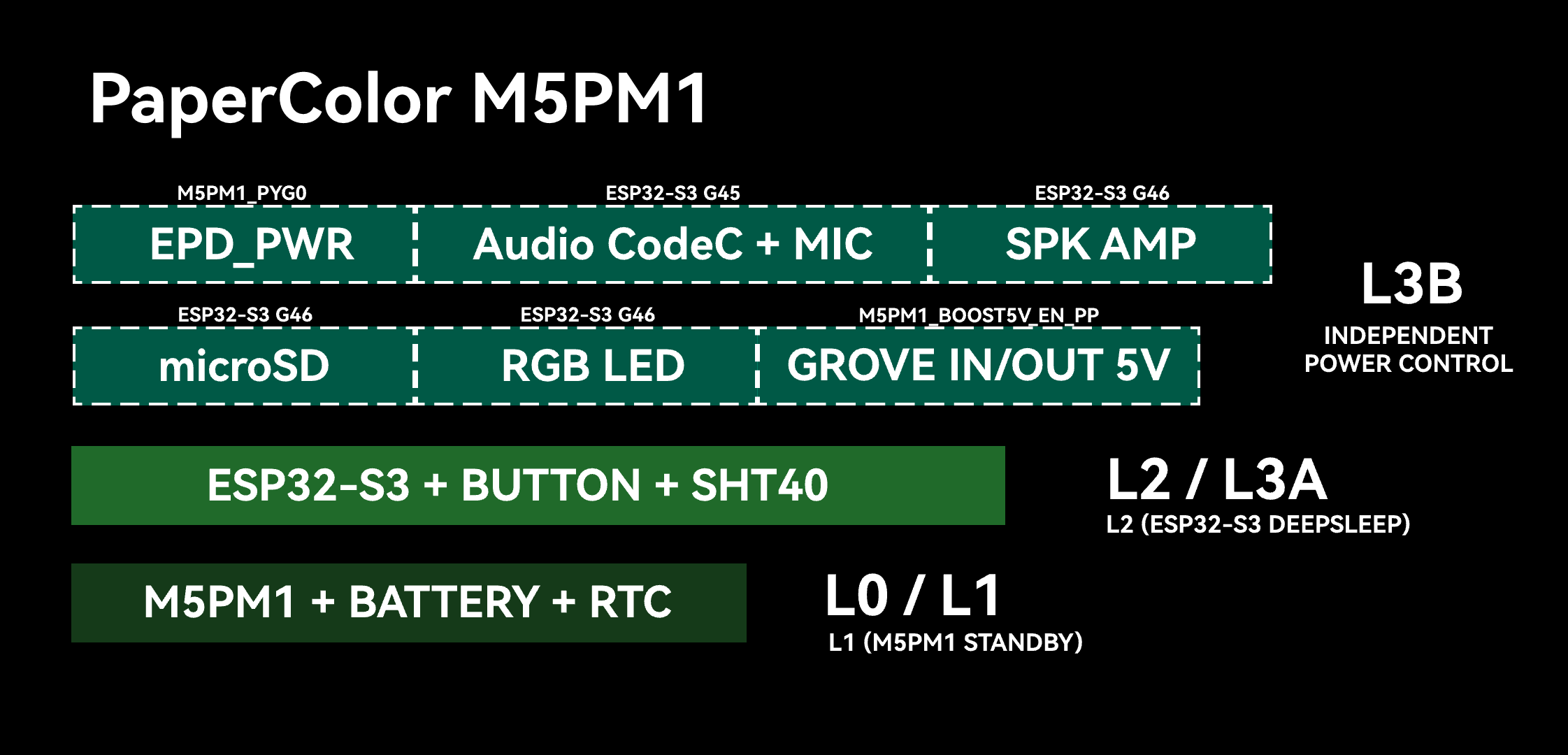
DCDC3V3_EN_PP, LDO3V3_EN_PP, CHG_EN_PP are on).L0 / L1
At this power level, the battery maintains power supply to M5PM1 and the RTC. As long as the battery is not depleted, this power layer remains active, and M5PM1 supports basic power on/off button operations.
The L0 level indicates that M5PM1 has entered the powered-off state.
At the L1 level, M5PM1 is in standby state.
L2 / L3A
At this power level, the ESP32-S3 main controller, SHT40I temperature and humidity sensor, and the pull-up resistors for user buttons are powered (3V3_L2).
When the ESP32-S3 is in sleep mode, the power is at L2 level. When the ESP32-S3 is in active operation, the power is at L3A level.
The ESP32-S3 can cut its own power supply (L2->L1/L0) by putting M5PM1 into sleep mode.
L3B
This power level allows further control of on-board peripheral power supply via M5PM1 and ESP32-S3 GPIOs.
| ESP32S3R8 | G45 |
|---|---|
| ES8311 & ES7210 Power (CODEC_3V3_L3B) | AUDIO_PWR_EN |
| ESP32S3R8 | G46 |
|---|---|
| AW8737A | SPK_EN |
- G46 (SPK_EN): Speaker amplifier enable
- G45 (AUDIO_PWR_EN): Audio codec chip and microphone power supply
| M5PM1 | DCDC3V3_EN_PP | LDO3V3_EN_PP | BOOST5V_EN_PP |
|---|---|---|---|
| 3V3_L2 | PY_MPWR_EN | ||
| RGB LED | PY_RGB_PWR_EN | ||
| Grove | PY_GROVE_OUT_EN |
- DCDC3V3_EN_PP (PY_MPWR_EN): 3V3_L2 power switch
- LDO3V3_EN_PP (PY_RGB_PWR_EN): RGB LED power switch
- BOOST5V_EN_PP (PY_GROVE_OUT_EN): Grove expansion interface power direction control
| M5PM1 | PYG0 | PYG2 | PYG4 | PYG3 | PYG1 |
|---|---|---|---|---|---|
| E-Paper | PY_EPD_EN | ||||
| RTC | RTC_IRQ | ||||
| microSD | PY_SD_DET_EN | PY_SD_PWR_EN | CARD_DEC |
- PYG0 (PY_EPD_EN): Enable e-paper display power supply
- PYG2 (RTC_IRQ): RTC interrupt signal
- PYG3 (PY_SD_PWR_EN): microSD module power supply
- PYG4 (PY_SD_DET_EN): microSD detection function enable, enables pull-up
- PYG1 (CARD_DEC): microSD card insertion detection
2. M5PM1 Sleep
Manual Sleep
M5PM1 can be manually put into sleep mode via software to reduce overall power consumption. By default, triggering sleep directly will fall back to L0 power level, at which point only M5PM1 and the RTC remain powered.
pm1.shutdown();In certain special use cases (e.g., ESP32-S3 SoC sleep mode), M5PM1 can be allowed to enter sleep while maintaining power to certain peripheral levels, for use as wake-up sources or state retention.
Such applications require configuring the power switch pin states for the corresponding levels and activating state retention before M5PM1 enters sleep mode.
I2C Idle Sleep
M5PM1 supports configuring automatic sleep on I2C idle communication to reduce overall power consumption. After entering sleep, the first communication between the ESP32-S3 and M5PM1 is used to wake M5PM1 and will therefore fail; effective communication resumes from the next transaction after wake-up.
m5pm1_err_t setI2cSleepTime(uint8_t seconds);3. M5PM1 Timer
M5PM1 supports a timer function that, upon expiry, executes a specified action such as power on, power off, or reset.
m5pm1_err_t timerSet(uint32_t seconds, m5pm1_tim_action_t action);typedef enum {
M5PM1_TIM_ACTION_STOP = 0b000, // Stop, no action
// Stop, no action
M5PM1_TIM_ACTION_FLAG = 0b001, // Set flag only
// Set flag only
M5PM1_TIM_ACTION_REBOOT = 0b010, // System reboot
// System reboot
M5PM1_TIM_ACTION_POWERON = 0b011, // Power on
// Power on
M5PM1_TIM_ACTION_POWEROFF = 0b100 // Power off
// Power off
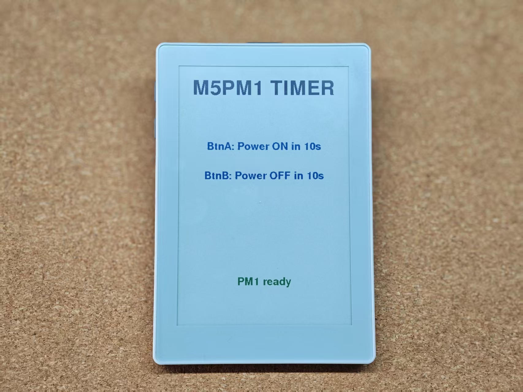
} m5pm1_tim_action_t;Scheduled Power On / Off Example
Example description: After the device powers on, pressing button A configures a 10-second timer to trigger a power-on event, after which the device shuts down and waits to be woken up. Pressing button B configures a 10-second timer to trigger an M5PM1 power-off (the device can be powered back on by pressing the power button).
#include <M5Unified.h>
#include <M5PM1.h>
#include <Wire.h>
#include <Adafruit_NeoPixel.h>

static constexpr uint32_t POWERON_SECONDS = 10;
static constexpr uint32_t POWEROFF_SECONDS = 10;
static constexpr uint8_t LED_PIN = 21;
static constexpr uint8_t LED_COUNT = 2;

M5PM1 pm1;
M5Canvas canvas(&M5.Display);
Adafruit_NeoPixel pixels(LED_COUNT, LED_PIN, NEO_GRB + NEO_KHZ800);

static bool pm1_ready = false;

static void setAllLeds(uint32_t color)
{
    for (uint8_t i = 0; i < LED_COUNT; ++i) {
        pixels.setPixelColor(i, color);
    }
    pixels.show();
}

static void drawScreen(const char* status)
{
    const int w = M5.Display.width();
    const int h = M5.Display.height();

    canvas.fillSprite(WHITE);
    canvas.setTextDatum(top_center);
    canvas.setTextColor(BLACK);

    canvas.setFont(&fonts::FreeSansBold24pt7b);
    canvas.drawString("M5PM1 TIMER", w / 2, 34);

    canvas.setFont(&fonts::FreeSansBold12pt7b);
    canvas.setTextColor(BLUE);
    canvas.drawString("BtnA: Power ON in 10s", w / 2, 180);
    canvas.drawString("BtnB: Power OFF in 10s", w / 2, 248);

    canvas.setTextColor(pm1_ready ? GREEN : RED);
    canvas.drawString(status, w / 2, h - 110);

    canvas.pushSprite(0, 0);
}

void setup(void)
{
    auto cfg = M5.config();
    cfg.clear_display = false;
    M5.begin(cfg);

    Serial.begin(115200);
    M5.Display.setEpdMode(epd_mode_t::epd_quality);

    canvas.createSprite(M5.Display.width(), M5.Display.height());

    m5pm1_err_t err = pm1.begin(&M5.In_I2C, M5PM1_DEFAULT_ADDR, M5PM1_I2C_FREQ_100K);
    pm1_ready       = (err == M5PM1_OK);

    if (pm1_ready) {
        pm1.setLdoEnable(true);
    }

    pixels.begin();
    pixels.setBrightness(60);
    setAllLeds(0);

    if (pm1_ready) {
        Serial.println("PM1 init ok");
        drawScreen("PM1 ready");
        setAllLeds(pixels.Color(0, 255, 0));
    } else {
        Serial.printf("PM1 init failed: %d\n", (int)err);
        drawScreen("PM1 init failed");
        setAllLeds(pixels.Color(255, 0, 0));
    }
}

void loop(void)
{
    M5.update();

    if (!pm1_ready) {
        delay(20);
        return;
    }

    if (M5.BtnA.wasPressed()) {
        Serial.printf("BtnA: timer power on in %lu s\n", POWERON_SECONDS);
        setAllLeds(pixels.Color(255, 255, 0));
        m5pm1_err_t err = pm1.timerSet(POWERON_SECONDS, M5PM1_TIM_ACTION_POWERON);
        if (err != M5PM1_OK) {
            Serial.printf("timerSet POWERON failed: %d\n", (int)err);
            drawScreen("BtnA failed");
            setAllLeds(pixels.Color(255, 0, 0));
        }
        delay(1000);
        pm1.shutdown();
    }

    if (M5.BtnB.wasPressed()) {
        Serial.printf("BtnB: timer poweroff in %lu s\n", POWEROFF_SECONDS);
        setAllLeds(pixels.Color(0, 0, 255));
        m5pm1_err_t err = pm1.timerSet(POWEROFF_SECONDS, M5PM1_TIM_ACTION_POWEROFF);
        if (err != M5PM1_OK) {
            Serial.printf("timerSet POWEROFF failed: %d\n", (int)err);
            drawScreen("BtnB failed");
            setAllLeds(pixels.Color(255, 0, 0));
        }
    }

    delay(20);
}
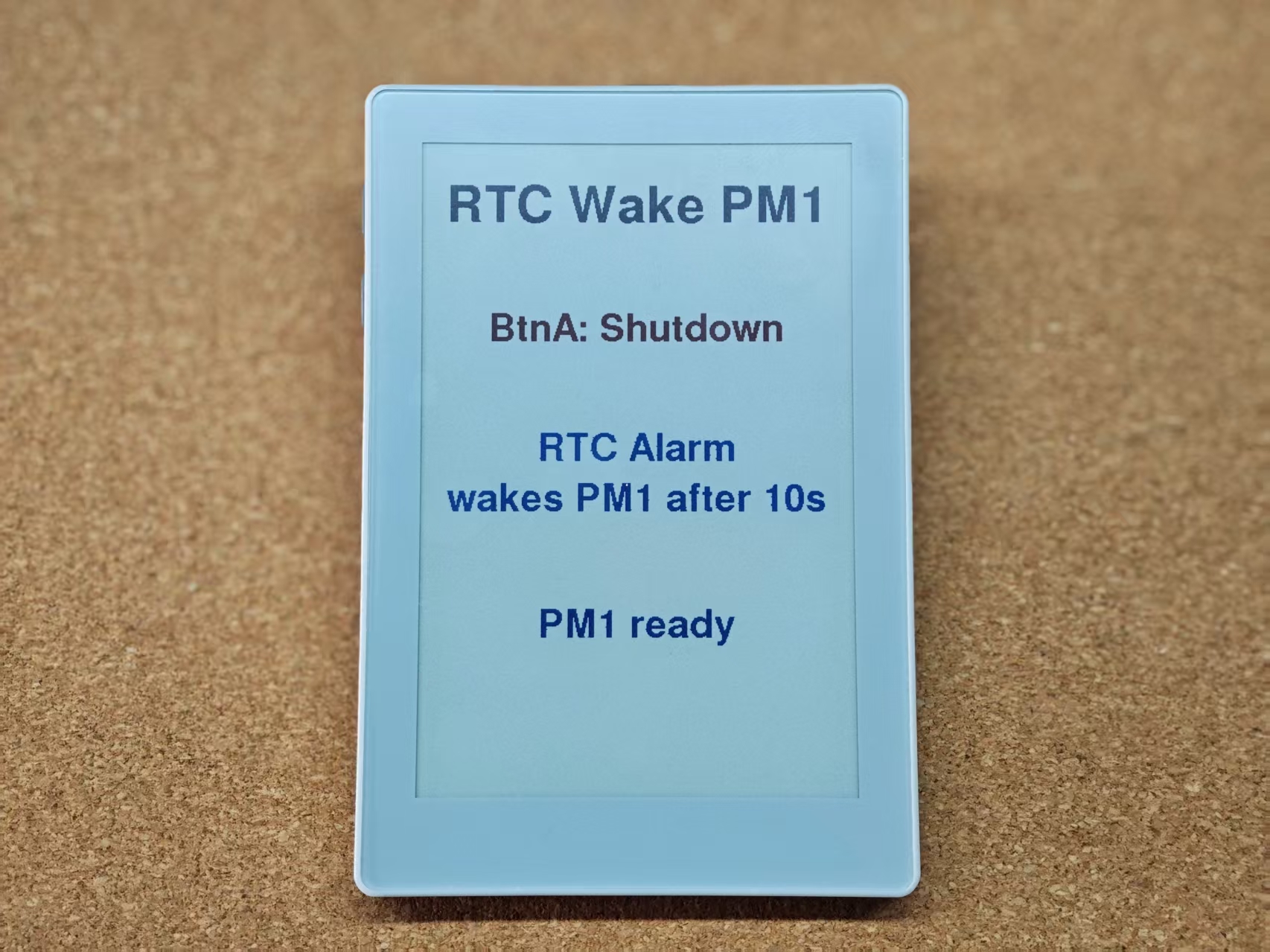
4. RTC M5PM1 Wake-Up
After the device powers on, pressing button A configures an RTC timed wake-up and puts M5PM1 into sleep mode. At this point, only the minimum L0 power level is maintained to keep the IMU and M5PM1 running, until the RTC triggers a wake-up signal to restart M5PM1. Upon wake-up, M5PM1 will re-execute the L1, L2, and L3A power-on sequence, and the ESP32-S3 will re-run its initialization.
#include <M5Unified.h>
#include <M5PM1.h>
#include <Wire.h>
#include <Adafruit_NeoPixel.h>

static constexpr int RTC_WAKE_AFTER_SECONDS = 20;

M5Canvas canvas(&M5.Display);
M5PM1 pm1;
Adafruit_NeoPixel pixels(2, 21, NEO_GRB + NEO_KHZ800);

static bool pm1_ready = false;

static void setAllLeds(uint32_t color)
{
    pixels.setPixelColor(0, color);
    pixels.setPixelColor(1, color);
    pixels.show();
}

static void drawScreen(const char* status, uint32_t status_color)
{
    const int w = M5.Display.width();
    const int h = M5.Display.height();

    canvas.fillSprite(WHITE);
    canvas.setTextDatum(top_center);

    canvas.setFont(&fonts::FreeSansBold24pt7b);
    canvas.setTextColor(BLACK);
    canvas.drawString("RTC Wake PM1", w / 2, 40);

    canvas.setFont(&fonts::FreeSansBold18pt7b);
    canvas.setTextColor(RED);
    canvas.drawString("BtnA: Shutdown", w / 2, 160);

    canvas.setTextColor(BLUE);
    canvas.drawString("RTC Alarm", w / 2, 270);
    canvas.drawString("wakes PM1 after 10s", w / 2, 316);

    canvas.setTextColor(status_color);
    canvas.drawString(status, w / 2, 430);

    canvas.pushSprite(0, 0);
}

void setup(void)
{
    auto cfg          = M5.config();
    cfg.clear_display = false;
    M5.begin(cfg);
    Serial.begin(115200);

    M5.Display.setEpdMode(epd_mode_t::epd_quality);
    canvas.createSprite(M5.Display.width(), M5.Display.height());

    pixels.begin();
    pixels.setBrightness(80);
    setAllLeds(0);

    m5pm1_err_t err = pm1.begin(&M5.In_I2C, M5PM1_DEFAULT_ADDR, M5PM1_I2C_FREQ_100K);
    pm1_ready       = (err == M5PM1_OK);

    if (pm1_ready) {
        pm1.setLdoEnable(true);
        setAllLeds(pixels.Color(0, 255, 0));
        drawScreen("PM1 ready", GREEN);
        Serial.println("PM1 initialization successful");
        pm1.gpioSetWakeEnable(M5PM1_GPIO_NUM_2, true);
        pm1.gpioSetWakeEdge(M5PM1_GPIO_NUM_2, M5PM1_GPIO_WAKE_FALLING);  // Falling edge

    } else {
        setAllLeds(pixels.Color(255, 0, 0));
        drawScreen("PM1 init failed", RED);
        Serial.printf("PM1 initialization failed, error code: %d\n", err);
    }
}

void loop(void)
{
    M5.update();

    if (!pm1_ready) {
        delay(20);
        return;
    }

    if (M5.BtnA.wasPressed()) {
        M5.Rtc.disableIRQ();
        M5.Rtc.clearIRQ();
        M5.Rtc.setAlarmIRQ(RTC_WAKE_AFTER_SECONDS);

        for (int i = 0; i < 3; i++) {
            setAllLeds(pixels.Color(255, 0, 0));
            delay(200);
            setAllLeds(0);
            delay(200);
        }
        pm1.shutdown();
    }

    delay(20);
}