

Arduino入門
2. デバイス&サンプル
3. M5Unified
4. M5GFX
5. 拡張モジュール&サンプル
Unit
Atomic
Tab5
IoT
アクセサリー
Stamp C6LoRa Arduino プログラムのコンパイルと書き込み
1. 準備
- Arduino IDE のインストール: Arduino IDE インストールチュートリアルを参考に、IDE のインストールを完了させてください。
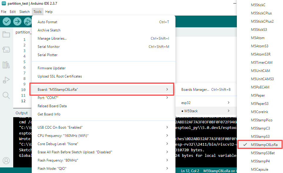
- ボードマネージャーのインストール: 基本環境構築チュートリアルを参考に、M5Stack ボードマネージャーのインストールを完了し、開発ボード
M5StampC6LoRaを選択してください。
- ボードマネージャーのインストール: 基本環境構築チュートリアルを参考に、M5Stack ボードマネージャーのインストールを完了し、開発ボード
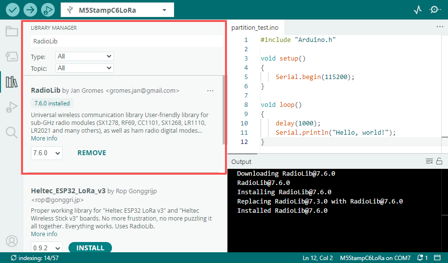
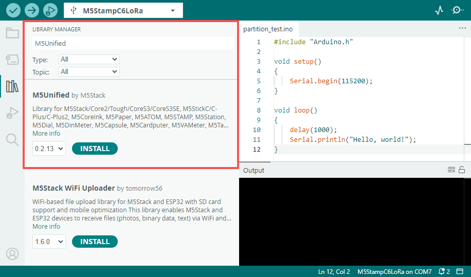
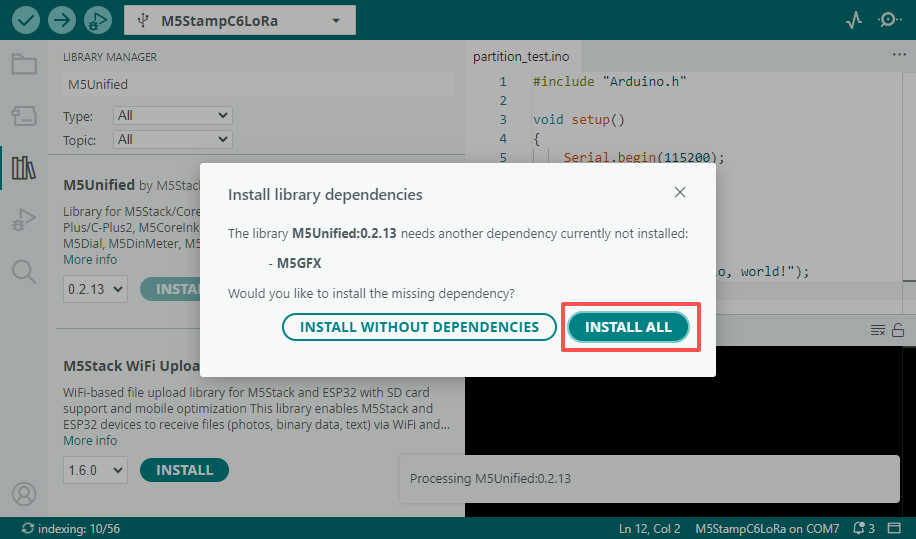
- 依存ライブラリのインストール:ライブラリマネージャーインストールチュートリアルを参考に、最新版の
M5Unified、M5GFX、RadioLibドライバライブラリのインストールを完了し、プロンプトに従ってすべての依存ライブラリをインストールしてください。
- 依存ライブラリのインストール:ライブラリマネージャーインストールチュートリアルを参考に、最新版の
2. 書き込み方法
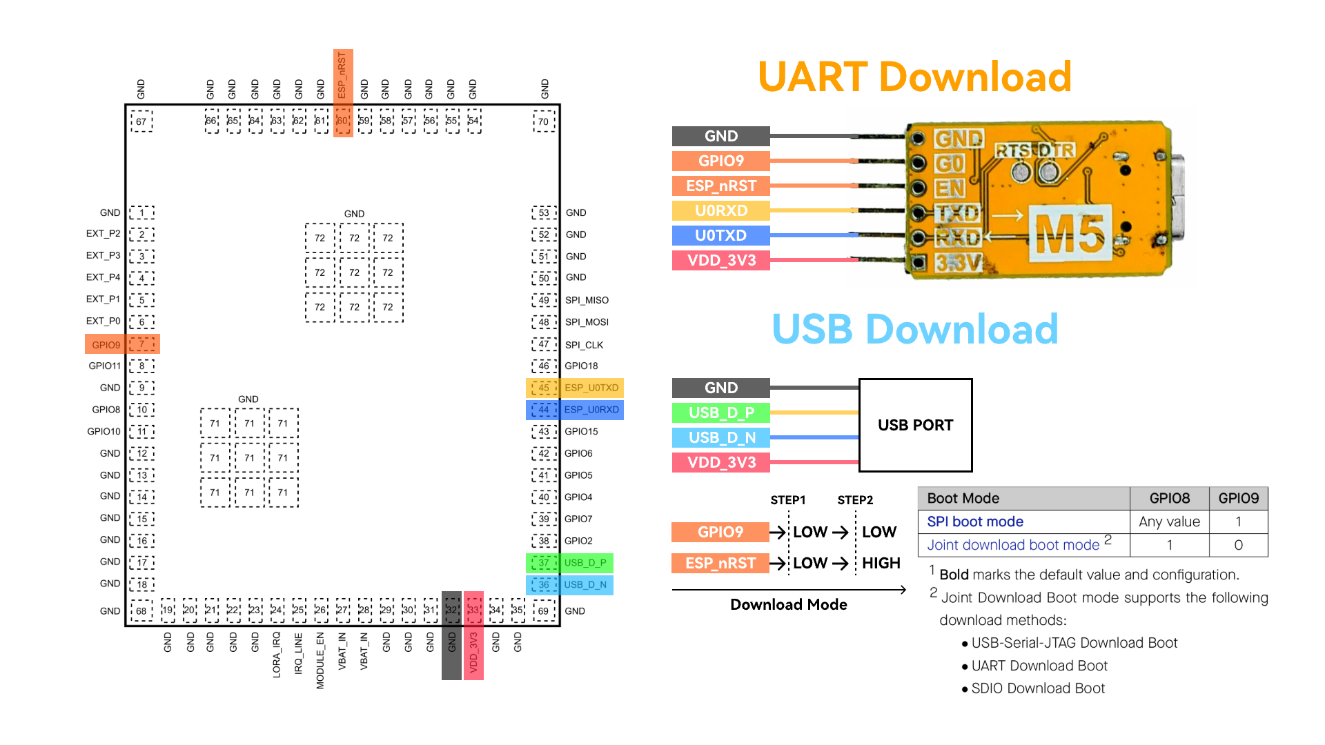
Stamp C6LoRa は UART または USB インターフェースを介したプログラムのダウンロードをサポートしています。ダウンロードする前に、Boot ピン (GPIO9) を低レベルに保持した状態で、モジュールをリセットしてダウンロードモードに移行させる必要があります。
- UART 方式でダウンロードする場合は、USB-TTL 変換ボードが必要です。以下の配線図は、ESP32 Downloader 変換ボードを使用して Stamp C6LoRa の UART プログラム書き込みインターフェースに接続する例です。
- ESP32 Downloader は自動ダウンロード回路を搭載しており、プログラムの書き込み実行時に自動的にモジュールをダウンロードモードに制御します。
- USB 方式でダウンロードする場合は、Boot ピンを低レベルに保持した状態で、RST ピンを介してモジュールをリセット (低レベル -> 高レベル) し、ダウンロードモードに移行させる必要があります。
ダウンロードモードに入った後、Arduino IDE で対応するデバイスのポートを選択して書き込みを行うことができます。
3. プログラムのコンパイル & 書き込み
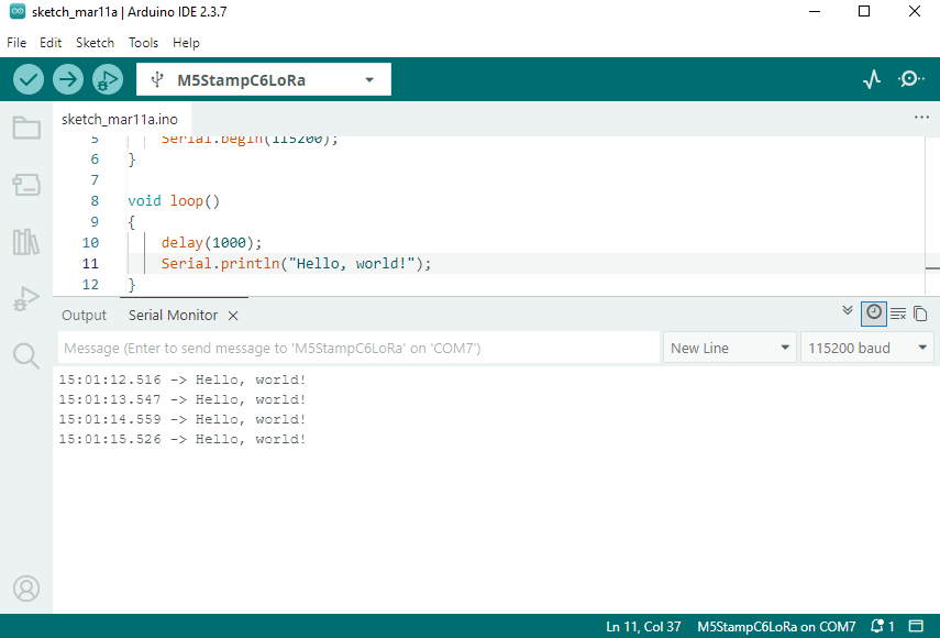
Arduino IDE のワークスペースに以下のコードを貼り付け、書き込みボタンをクリックすると、プログラムのコンパイルと書き込みが自動的に行われます。
ログ出力
Tools->USB CDC On Boot オプションはデフォルトで Enabled になっており、モジュールのデフォルトログは USB インターフェースに出力されます。ログの出力を UART0 に切り替えたい場合は、このオプションを Disabled に設定してください。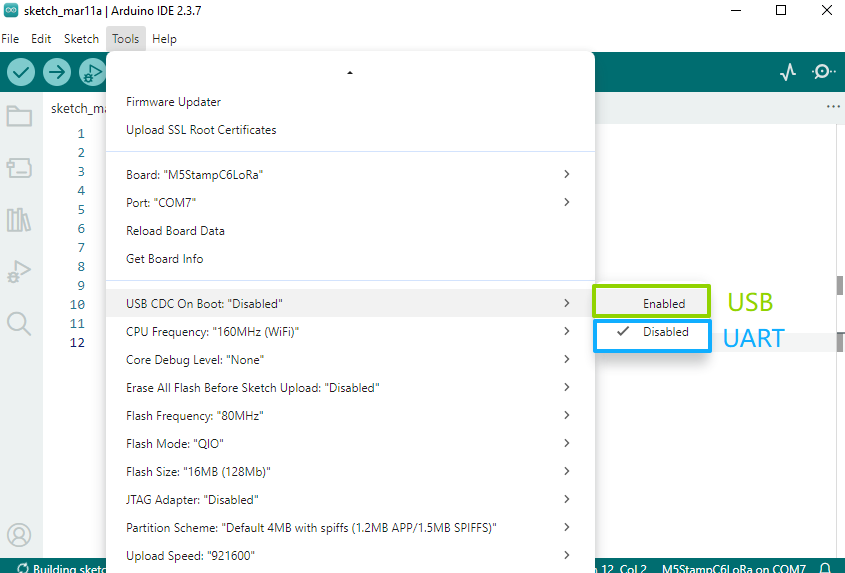
Hello World
cpp
1 2 3 4 5 6 7 8 9 10 11 12
#include "Arduino.h"

void setup()
{
    Serial.begin(115200);
}

void loop()
{
    delay(1000);
    Serial.println("Hello, world!");
}
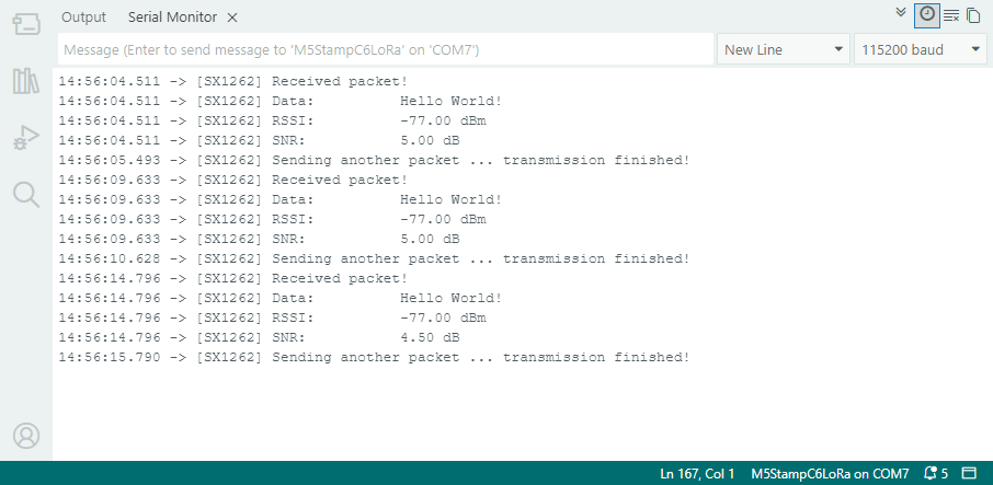
LoRa Ping Pong
以下は LoRa Ping Pong テストプログラムです。2 つの Stamp C6LoRa モジュールを使用する必要があります。モジュールの電源を順番に(時間差をおいて)入れると、自動的に相互の送受信テストが開始されます。
- サンプルプログラムでは、LORA_IRQ は GPIO7 を割り込み信号受信ピンとして使用します。テスト時には、モジュールの LORA_IRQ ピンを GPIO7 に接続してください。
- 使用前に LoRa アンテナを接続し、RF 回路の損傷を避けてください。
cpp
1 2 3 4 5 6 7 8 9 10 11 12 13 14 15 16 17 18 19 20 21 22 23 24 25 26 27 28 29 30 31 32 33 34 35 36 37 38 39 40 41 42 43 44 45 46 47 48 49 50 51 52 53 54 55 56 57 58 59 60 61 62 63 64 65 66 67 68 69 70 71 72 73 74 75 76 77 78 79 80 81 82 83 84 85 86 87 88 89 90 91 92 93 94 95 96 97 98 99 100 101 102 103 104 105 106 107 108 109 110 111 112 113 114 115 116 117 118 119 120 121 122 123 124 125 126 127 128 129 130 131 132 133 134 135 136 137 138 139 140 141 142 143 144 145 146 147 148 149 150 151 152 153 154 155 156 157 158 159 160 161 162 163 164 165 166 167 168 169 170
#include <Arduino.h>
#include <SPI.h>
#include <RadioLib.h>
#include <M5Unified.h>
#include "utility/PI4IOE5V6408_Class.hpp"

// Stamp C6LoRa board mapping
#define I2C_SDA_PIN 10
#define I2C_SCL_PIN 8

// SX1262 base pins on Stamp C6LoRa
#define SX1262_MOSI_PIN 21
#define SX1262_MISO_PIN 22
#define SX1262_SCK_PIN  20
#define SX1262_CS_PIN   23
#define SX1262_IRQ_PIN  7
#define SX1262_BUSY_PIN 19

// PI4IOE5V6408 -> SX1262 control lines
#define SX_LNA_EN_PIN 5
#define SX_ANT_SW_PIN 6
#define SX_NRST_PIN   7

// SX1262: CS, IRQ(DIO1), NRST, BUSY
SX1262 radio = new Module(SX1262_CS_PIN, SX1262_IRQ_PIN, RADIOLIB_NC, SX1262_BUSY_PIN);

m5::I2C_Class i2c_bus_0;
// Stamp C6LoRa uses PI4IOE5V6408 at 0x43 to control SX1262 power path
m5::PI4IOE5V6408_Class ioe(0x43, 400000, &i2c_bus_0);

// save transmission state between loops
int transmissionState = RADIOLIB_ERR_NONE;

// flag to indicate transmission/reception state
bool transmitFlag = false;

// flag to indicate that a packet was sent/received
volatile bool operationDone = false;

void setFlag(void)
{
    operationDone = true;
}

static bool initIoExpanderAndRfPath()
{
    if (!i2c_bus_0.begin(I2C_NUM_0, I2C_SDA_PIN, I2C_SCL_PIN)) {
        Serial.println("[I2C] begin failed");
        return false;
    }

    if (!ioe.begin()) {
        Serial.println("[IOE] PI4IOE5V6408 begin failed");
        return false;
    }

    ioe.setHighImpedance(SX_NRST_PIN, false);
    ioe.setHighImpedance(SX_ANT_SW_PIN, false);
    ioe.setHighImpedance(SX_LNA_EN_PIN, false);
    ioe.setDirection(SX_NRST_PIN, true);
    ioe.setDirection(SX_ANT_SW_PIN, true);
    ioe.setDirection(SX_LNA_EN_PIN, true);
    delay(100);

    // SX1262 reset and RF path enable sequence.
    ioe.digitalWrite(SX_NRST_PIN, false);
    delay(100);
    ioe.digitalWrite(SX_NRST_PIN, true);
    ioe.digitalWrite(SX_ANT_SW_PIN, true);
    ioe.digitalWrite(SX_LNA_EN_PIN, true);
    delay(10);

    return true;
}

void setup()
{
    Serial.begin(115200);
    delay(300);
    Serial.println("\n[Stamp C6LoRa] RadioLib ping-pong start");

    SPI.begin(SX1262_SCK_PIN, SX1262_MISO_PIN, SX1262_MOSI_PIN, SX1262_CS_PIN);

    if (!initIoExpanderAndRfPath()) {
        while (true) {
            delay(1000);
        }
    }

    Serial.print("[SX1262] Initializing... ");
    int state = radio.begin(868.0, 125.0, 12, 5, 0x34, 22, 20, 3.0, true);
    if (state != RADIOLIB_ERR_NONE) {
        Serial.print("failed, code: ");
        Serial.println(state);
        while (true) {
            delay(1000);
        }
    }
    Serial.println("ok");

    // One callback handles both TX done and RX done on SX1262 DIO1.
    radio.setDio1Action(setFlag);

    // Send first PING packet.
    Serial.print("[SX1262] Sending first packet... ");
    transmissionState = radio.startTransmit("PING");
    if (transmissionState == RADIOLIB_ERR_NONE) {
        Serial.println("ok");
        transmitFlag = true;
    }
}

void loop()
{
    // check if the previous operation finished
    if (operationDone) {
        // reset flag
        operationDone = false;

        if (transmitFlag) {
            // the previous operation was transmission, listen for response
            // print the result
            if (transmissionState == RADIOLIB_ERR_NONE) {
                // packet was successfully sent
                Serial.println(F("transmission finished!"));

            } else {
                Serial.print(F("failed, code "));
                Serial.println(transmissionState);
            }

            // listen for response
            radio.startReceive();
            transmitFlag = false;

        } else {
            // the previous operation was reception
            // print data and send another packet
            String str;
            int state = radio.readData(str);

            if (state == RADIOLIB_ERR_NONE) {
                // packet was successfully received
                Serial.println(F("[SX1262] Received packet!"));

                // print data of the packet
                Serial.print(F("[SX1262] Data:\t\t"));
                Serial.println(str);

                // print RSSI (Received Signal Strength Indicator)
                Serial.print(F("[SX1262] RSSI:\t\t"));
                Serial.print(radio.getRSSI());
                Serial.println(F(" dBm"));

                // print SNR (Signal-to-Noise Ratio)
                Serial.print(F("[SX1262] SNR:\t\t"));
                Serial.print(radio.getSNR());
                Serial.println(F(" dB"));
            }

            // wait a second before transmitting again
            delay(1000);

            // send another one
            Serial.print(F("[SX1262] Sending another packet ... "));
            transmissionState = radio.startTransmit("Hello World!");
            transmitFlag      = true;
        }
    }
}
4. API
Stamp C6LoRa は LoRa ドライバとして RadioLib ライブラリを使用しています。詳細な API については以下のドキュメントを参照してください:
Page Tools