

Arduino 上手教程
2. 设备开发 & 案例程序
3. M5Unified
4. M5GFX
5. 拓展模块
Unit
Atomic
Tab5
IoT
Atomic HDriver Base Arduino 使用教程
1. 准备工作
环境配置: 参考 Arduino IDE 上手教程完成 IDE 安装,并根据实际使用的开发板安装对应的板管理,与需要的驱动库。
使用到的驱动库:
使用到的硬件产品:

2. 案例程序
- 本教程中使用的主控设备为 AtomS3 ,搭配 Atomic HDriver Base,信号输出引脚为
G6(IN1)、G7(IN2)。
cpp
1 2 3 4 5 6 7 8 9 10 11 12 13 14 15 16 17 18 19 20 21 22 23 24 25 26 27 28 29 30 31 32 33 34 35 36 37 38 39 40 41 42 43 44 45 46 47 48 49 50
#include "M5Unified.h"

const int IN1_PIN       = 6;
const int IN2_PIN       = 7;
const int VIN_PIN       = 8;
const int FAULT_PIN     = 5;

int freq          = 10000;
int resolution    = 10;
bool direction    = true;

void setup() {
    M5.begin();

    M5.Display.setTextColor(GREEN);
    M5.Display.setTextDatum(middle_center);
    M5.Display.setFont(&fonts::Orbitron_Light_24);
    M5.Display.drawString("H-Driver", M5.Display.width() / 2, M5.Display.height() / 2);

    ledcAttach(IN1_PIN, freq, resolution);
    ledcAttach(IN2_PIN, freq, resolution);
    pinMode(VIN_PIN, INPUT);
    pinMode(FAULT_PIN, INPUT);
    ledcWrite(IN1_PIN, 0);
    ledcWrite(IN2_PIN, 0);
}

void loop() {
    if (M5.BtnA.pressedFor(1000)) {
        ledcWrite(IN1_PIN, 0);
        ledcWrite(IN2_PIN, 0);
    }

    if (M5.BtnA.wasPressed()) {
        if (direction) {
            ledcWrite(IN1_PIN, 300);
            ledcWrite(IN2_PIN, 0);
        } else {
            ledcWrite(IN1_PIN, 0);
            ledcWrite(IN2_PIN, 300);
        }
        direction = !direction;
    }

    M5.update();
    if (digitalRead(FAULT_PIN) == 0) {
        M5.Display.clear();
        M5.Display.drawString("FAULT!", M5.Display.width() / 2, M5.Display.height() / 2);
    }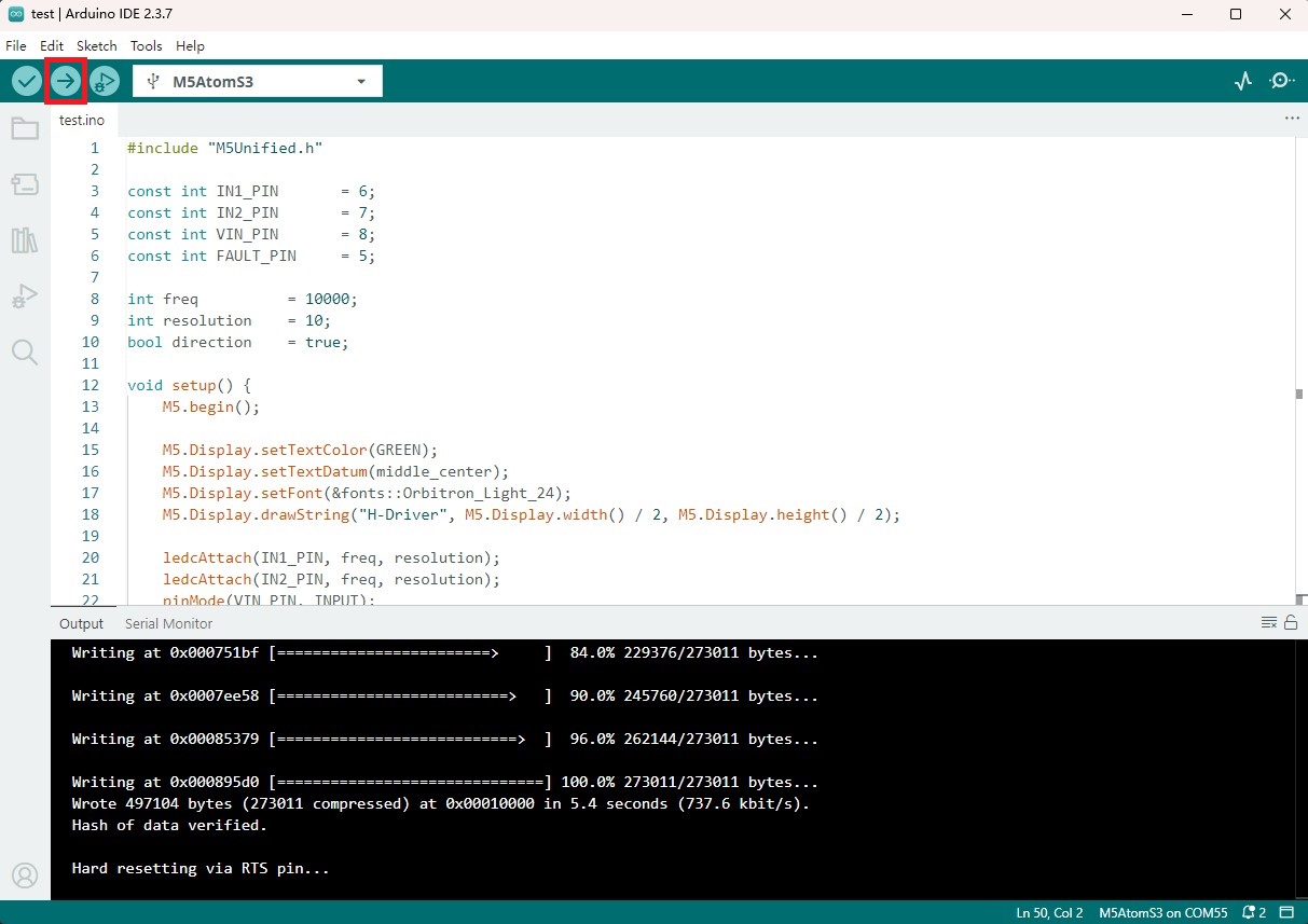
}3. 编译上传
- 1. AtomS3 长按复位按键 (大约 2 秒) 直到内部绿色 LED 灯亮起,便可松开,此时设备已进入下载模式,等待烧录。
说明
不同设备进行程序烧录前需要进入下载模式,不同的主控设备该步骤可能有所不同。详情可参考Arduino IDE上手教程页面底部的设备程序下载教程列表,查看具体的操作方式。
- 2. 选中设备端口,点击 Arduino IDE 左上角编译上传按钮,等待程序完成编译并上传至设备。
4. 直流电机控制
- 设备上电后,按动主控屏幕,直流电机将开始正转,再次按动屏幕,电机反转。长按屏幕 1 秒,电机可停止转动。(下方视频中使用的是 N20 直流震动电机)
Page Tools