


Arduino Quick Start
2. Devices & Examples
3. M5Unified
4. M5GFX
5. Extensions
Unit
Atomic
Tab5
IoT
Accessories
Unit PoE-P4 Display Output
Display output example programs for Unit PoE-P4 used with AddOn Display Out For PoE-P4.
Notes
This function requires the
AddOn Display Out For PoE-P4 module. First confirm that the 24P FPC cable is connected correctly, then connect the module's HDMI port to an external display. The current driver only supports two output timings: 1280 x 720@60Hz and 1920 x 1080@30Hz.Example Programs
Compile Requirements
- M5Stack board manager version >= 3.2.6
- Board option = M5UnitPoEP4
- M5Unified library version >= 0.2.18
- M5GFX library version >= 0.2.24
Note
1. The
2. The screen timing used in the example below is
M5UnitPoEP4HDMI driver is already included in M5GFX and does not need to be installed separately.2. The screen timing used in the example below is
1280 x 720@60Hz.Draw Display with M5GFX API
cpp
1 2 3 4 5 6 7 8 9 10 11 12 13 14 15 16 17 18 19 20 21 22 23 24 25 26 27 28 29 30 31 32 33 34 35 36 37 38 39 40 41 42 43 44 45 46 47 48 49 50 51 52 53 54 55 56 57 58 59 60 61 62 63 64 65 66 67 68 69 70 71 72 73 74 75 76 77 78 79 80 81 82 83 84 85 86 87 88 89 90 91 92 93 94 95 96 97 98 99 100 101 102 103 104 105 106 107 108
#include <M5GFX.h>
#include <M5UnitPoEP4HDMI.h>

namespace
{
M5UnitPoEP4HDMI::config_t makeDisplayConfig()
{
  M5UnitPoEP4HDMI::config_t cfg;
  // Unit PoE-P4 HDMI only supports 1280x720@60 or 1920x1080@30.
  // Set one of the supported timings explicitly here.
  cfg.width = 1280;
  cfg.height = 720;
  cfg.refresh_rate = 60;

  // Switch to 1080p30 by uncommenting the three lines below.
  // cfg.width = 1920;
  // cfg.height = 1080;
  // cfg.refresh_rate = 30;
  return cfg;
}
}

// Start the display with the selected HDMI timing.
M5UnitPoEP4HDMI display(makeDisplayConfig());

static constexpr size_t BAR_COUNT = 64;
static int max_y[BAR_COUNT];
static int prev_y[BAR_COUNT];
static uint32_t colors[BAR_COUNT];

void setup(void)
{
  display.init();
  display.startWrite();
  display.fillScreen(TFT_BLACK);

  if (display.isEPD())
  {
    display.setEpdMode(epd_mode_t::epd_fastest);
  }
  if (display.width() < display.height())
  {
    display.setRotation(display.getRotation() ^ 1);
  }

  for (int x = 0; x < BAR_COUNT; ++x)
  {
    prev_y[x] = display.height();
    max_y[x] = display.height();
    int r=0,g=0,b=0;
    switch (x >> 4)
    {
      case 0:
        b = 255;
        g = x*0x11;
        break;
      case 1:
        b = 255 - (x&15)*0x11;
        g = 255;
        break;
      case 2:
        g = 255;
        r = (x&15)*0x11;
        break;
      case 3:
        r = 255;
        g = 255 - (x&15)*0x11;
        break;
    }
    colors[x] = display.color888(r,g,b);
  }
}

void loop(void)
{
  int h = display.height();

  static int i;
  ++i;
  display.waitDisplay();
  for (int x = 0; x < BAR_COUNT; ++x)
  {
    int y = (h>>1) - (sinf((float)((x-24)*i) / 3210.0f) + sinf((float)((x-40)*i) / 1234.0f)) * (h>>2);

    int xpos = x * display.width() / BAR_COUNT;
    int w = ((x+1) * display.width() / BAR_COUNT) - xpos - 1;
    if (max_y[x]+1 >= y) { max_y[x] = y-1; }
    else
    {
      if ((i & 3) ==0 )
      {
        display.fillRect(xpos, max_y[x]-3, w, 1, TFT_BLACK);
        max_y[x]++;
      }
    }
    display.fillRect(xpos, max_y[x]-3, w, 3, TFT_WHITE);
    if (prev_y[x] < y)
    {
      display.fillRect(xpos, prev_y[x], w, y - prev_y[x], TFT_BLACK);
    }
    else
    {
      display.fillRect(xpos, y, w, prev_y[x] - y, colors[x]);
    }
    prev_y[x] = y;
  }
  display.display();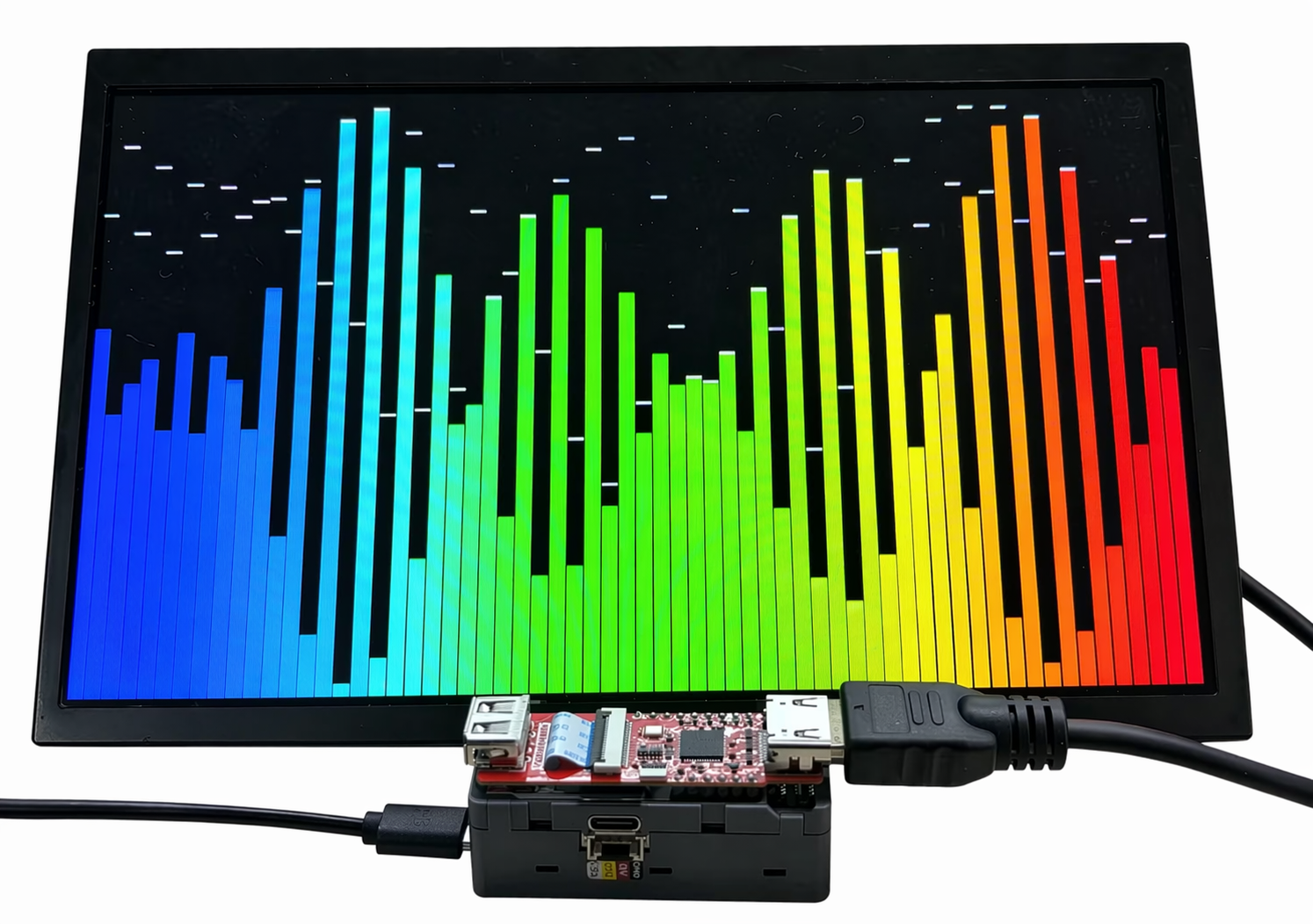
}This program initializes the HDMI display output of AddOn Display Out For PoE-P4 and draws a dynamic colorful waveform bar chart on the external display.
Display Images from SD Card
cpp
1 2 3 4 5 6 7 8 9 10 11 12 13 14 15 16 17 18 19 20 21 22 23 24 25 26 27 28 29 30 31 32 33 34 35 36 37 38 39 40 41 42 43 44 45 46 47 48 49 50 51 52 53 54 55 56 57 58 59 60 61 62 63 64 65
#include "FS.h"
#include "SD_MMC.h"
#include <M5Unified.h>
#include <M5GFX.h>
#include <M5UnitPoEP4HDMI.h>

namespace
{
M5UnitPoEP4HDMI::config_t makeDisplayConfig()
{
  M5UnitPoEP4HDMI::config_t cfg;
  // Unit PoE-P4 HDMI only supports 1280x720@60 or 1920x1080@30.
  // Set one of the supported timings explicitly here.
  cfg.width = 1280;
  cfg.height = 720;
  cfg.refresh_rate = 60;

  // Switch to 1080p30 by uncommenting the three lines below.
  // cfg.width = 1920;
  // cfg.height = 1080;
  // cfg.refresh_rate = 30;
  return cfg;
}
}

// Start the display with the selected HDMI timing.
M5UnitPoEP4HDMI display(makeDisplayConfig());

void setup()
{
    Serial.begin(115200);

    display.begin();

    if (display.width() < display.height()) {
        display.setRotation(display.getRotation() ^ 1);
    }

    if (!SD_MMC.setPins(SDMMC_CLK, SDMMC_CMD, SDMMC_D0, SDMMC_D1, SDMMC_D2, SDMMC_D3)) {
        Serial.println("SD_MMC pin change failed");
        return;
    }

    if (!SD_MMC.begin()) {
        Serial.println("SD_MMC begin failed");
        return;
    }

    Serial.println("SD_MMC begin success");

    uint8_t cardType = SD_MMC.cardType();
    if (cardType == CARD_NONE) {
        Serial.println("No SD card");
        return;
    }

    Serial.printf("Card size: %llu MB\n", SD_MMC.cardSize() / 1024 / 1024);

    display.drawJpgFile(SD_MMC, "/U221_AddOn_Display_Out_For_PoE-P4_Arduino_test_picture.jpg", 0, 0);
}

void loop()
{
    delay(1000);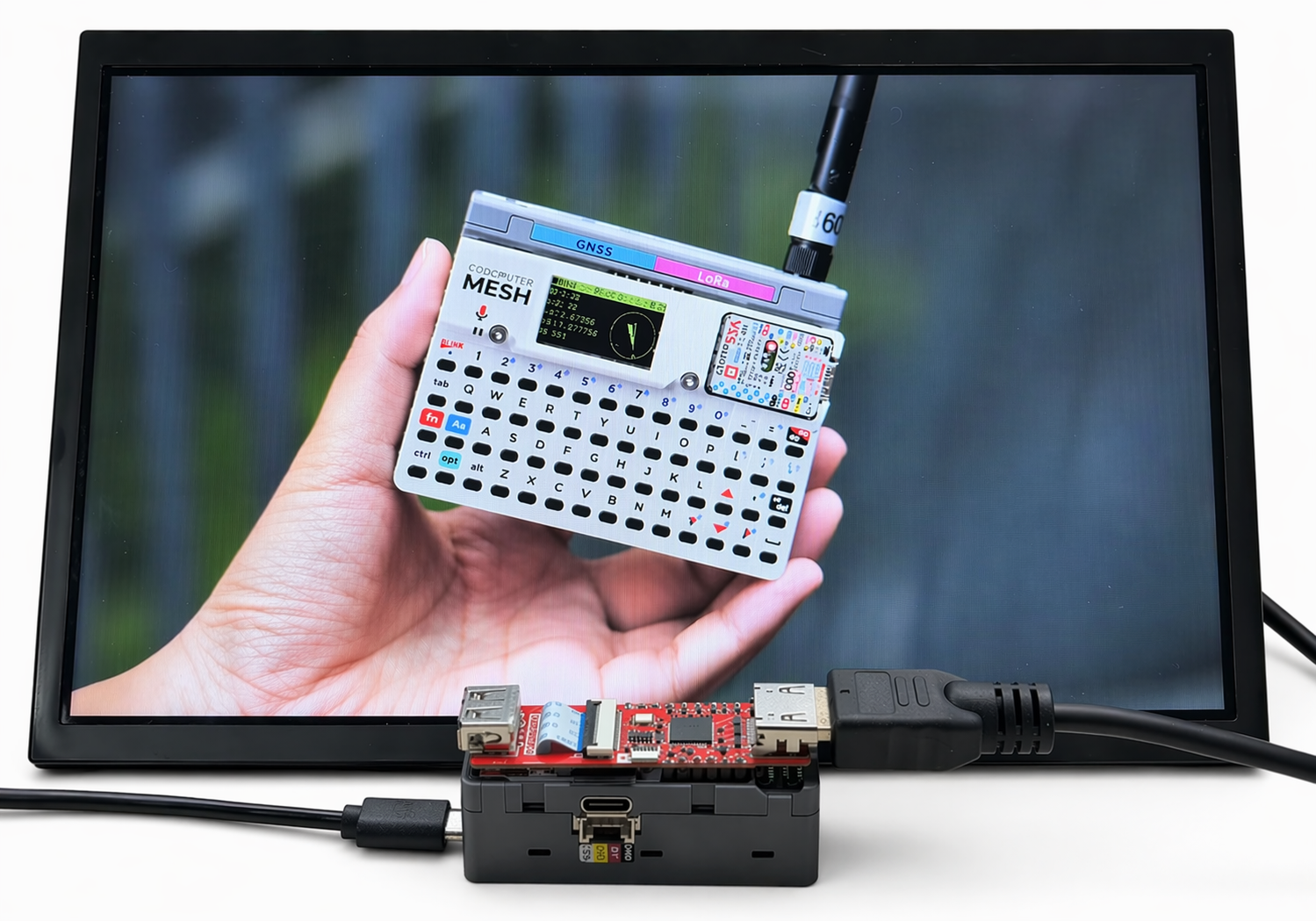
}After the program runs successfully, Unit PoE-P4 reads the image file from the microSD card and displays it on the external display.
Display Online Images
cpp
1 2 3 4 5 6 7 8 9 10 11 12 13 14 15 16 17 18 19 20 21 22 23 24 25 26 27 28 29 30 31 32 33 34 35 36 37 38 39 40 41 42 43 44 45 46 47 48 49 50 51 52 53 54 55 56 57 58 59 60 61 62 63 64 65 66 67 68 69 70 71 72 73 74 75 76 77 78 79 80 81 82 83 84 85 86 87 88 89 90 91 92 93 94 95 96 97 98 99 100 101 102 103 104 105 106 107 108 109 110 111 112 113 114 115 116 117 118 119 120 121 122 123 124 125 126 127 128 129 130 131 132 133 134 135 136 137 138 139 140 141 142 143 144 145 146 147 148 149 150 151 152 153 154 155 156 157 158 159 160 161 162 163 164 165 166 167 168 169 170 171 172 173 174 175 176 177 178 179 180
#include <ETH.h>
#include <HTTPClient.h>
#include <M5GFX.h>
#include <M5UnitPoEP4HDMI.h>

#define ETH_PHY_TYPE  ETH_PHY_IP101
#define ETH_PHY_ADDR  1
#define ETH_PHY_MDC   31
#define ETH_PHY_MDIO  52
#define ETH_PHY_POWER 51
#define ETH_CLK_MODE  EMAC_CLK_EXT_IN

namespace
{
M5UnitPoEP4HDMI::config_t makeDisplayConfig()
{
  M5UnitPoEP4HDMI::config_t cfg;
  // Unit PoE-P4 HDMI only supports 1280x720@60 or 1920x1080@30.
  // Set one of the supported timings explicitly here.
  cfg.width = 1280;
  cfg.height = 720;
  cfg.refresh_rate = 60;

  // Switch to 1080p30 by uncommenting the three lines below.
  // cfg.width = 1920;
  // cfg.height = 1080;
  // cfg.refresh_rate = 30;
  return cfg;
}
}

// Start the display with the selected HDMI timing.
M5UnitPoEP4HDMI display(makeDisplayConfig());

static const char *IMAGE_URL = "https://m5stack-doc.oss-cn-shenzhen.aliyuncs.com/1253/U221_AddOn_Display_Out_For_PoE-P4_Arduino_test_picture.jpg";
static bool eth_connected = false;

void onEvent(arduino_event_id_t event)
{
  switch (event)
  {
  case ARDUINO_EVENT_ETH_START:
    Serial.println("[ETH] Started");
    ETH.setHostname("unit-poe-p4");
    break;

  case ARDUINO_EVENT_ETH_CONNECTED:
    Serial.println("[ETH] Connected");
    break;

  case ARDUINO_EVENT_ETH_GOT_IP:
    Serial.println("[ETH] Got IP");
    Serial.println(ETH);
    eth_connected = true;
    break;

  case ARDUINO_EVENT_ETH_LOST_IP:
    Serial.println("[ETH] Lost IP");
    eth_connected = false;
    break;

  case ARDUINO_EVENT_ETH_DISCONNECTED:
    Serial.println("[ETH] Disconnected");
    eth_connected = false;
    break;

  case ARDUINO_EVENT_ETH_STOP:
    Serial.println("[ETH] Stopped");
    eth_connected = false;
    break;

  default:
    break;
  }
}

bool waitEthernet(uint32_t timeout_ms)
{
  uint32_t start = millis();
  while (!eth_connected && (millis() - start < timeout_ms))
  {
    Serial.printf(
        "[ETH] phyAddr=%lu, linkUp=%d, speed=%d Mbps, fullDuplex=%d, IP=%s\n",
        ETH.phyAddr(),
        ETH.linkUp(),
        ETH.linkSpeed(),
        ETH.fullDuplex(),
        ETH.localIP().toString().c_str());
    delay(1000);
  }

  return eth_connected;
}

void setup()
{
  Serial.begin(115200);
  delay(1000);

  // ---- 1. Display initialization ----
  Serial.println("[DISP] Initializing HDMI display...");
  display.begin();

  if (display.width() < display.height())
  {
    display.setRotation(display.getRotation() ^ 1);
  }

  display.fillScreen(TFT_BLACK);
  display.setTextColor(TFT_WHITE, TFT_BLACK);
  display.setTextSize(2);
  display.setTextDatum(datum_t::middle_center);
  display.drawString("Starting Ethernet...", display.width() / 2, display.height() / 2);

  // ---- 2. Ethernet initialization ----
  Network.onEvent(onEvent);
  Serial.println("[ETH] Initializing Ethernet...");
  bool eth_ok = ETH.begin(
      ETH_PHY_TYPE,
      ETH_PHY_ADDR,
      ETH_PHY_MDC,
      ETH_PHY_MDIO,
      ETH_PHY_POWER,
      ETH_CLK_MODE);

  Serial.printf("[ETH] ETH.begin result: %s\n", eth_ok ? "OK" : "FAILED");
  Serial.printf("[ETH] PHY addr: %lu\n", ETH.phyAddr());

  if (!eth_ok)
  {
    Serial.println("[ETH] ETH.begin() failed!");
    display.fillScreen(TFT_BLACK);
    display.setTextColor(TFT_RED, TFT_BLACK);
    display.drawString("ETH.begin Failed!", display.width() / 2, display.height() / 2);
    return;
  }

  display.fillScreen(TFT_BLACK);
  display.drawString("Waiting for IP...", display.width() / 2, display.height() / 2);

  bool network_ready = waitEthernet(20000);

  // ---- 3. Download and display JPEG ----
  if (network_ready)
  {
    Serial.printf("[ETH] Network ready. IP: %s\n", ETH.localIP().toString().c_str());

    display.fillScreen(TFT_BLACK);
    display.setTextColor(TFT_WHITE, TFT_BLACK);
    display.drawString("Downloading...", display.width() / 2, display.height() / 2);

    Serial.printf("[HTTP] Downloading: %s\n", IMAGE_URL);
    unsigned long dl_start = millis();
    bool ok = display.drawJpgUrl(IMAGE_URL, 0, 0);
    unsigned long dl_elapsed = millis() - dl_start;

    if (ok)
    {
      Serial.printf("[HTTP] Image displayed OK in %lu ms\n", dl_elapsed);
    }
    else
    {
      Serial.printf("[HTTP] Failed to download/decode after %lu ms\n", dl_elapsed);
      display.fillScreen(TFT_BLACK);
      display.drawString("Download Failed!", display.width() / 2, display.height() / 2);
    }
  }
  else
  {
    Serial.println("[ETH] Network timeout!");
    display.fillScreen(TFT_BLACK);
    display.setTextColor(TFT_RED, TFT_BLACK);
    display.drawString("Ethernet Timeout!", display.width() / 2, display.height() / 2);
  }
}

void loop(void)
{
  delay(1000);
}After the program runs successfully, Unit PoE-P4 connects to the Internet via Ethernet, downloads the JPG image file from the specified URL, and displays the image on the external display. The actual effect is the same as the example image shown in the SD card image display example.
Serial output example:
[ETH] Initializing Ethernet...
[ETH] Started
[ETH] Connected
[ETH] ETH.begin result: OK
[ETH] PHY addr: 1
[ETH] phyAddr=1, linkUp=1, speed=100 Mbps, fullDuplex=1, IP=0.0.0.0
[ETH] phyAddr=1, linkUp=1, speed=100 Mbps, fullDuplex=1, IP=0.0.0.0
[ETH] phyAddr=1, linkUp=1, speed=100 Mbps, fullDuplex=1, IP=0.0.0.0
[ETH] phyAddr=1, linkUp=1, speed=100 Mbps, fullDuplex=1, IP=0.0.0.0
[ETH] phyAddr=1, linkUp=1, speed=100 Mbps, fullDuplex=1, IP=0.0.0.0
[ETH] Got IP
*eth0: <UP,100M,FULL_DUPLEX,AUTO,ADDR:0x1> (DHCPC,GARP,IP_MOD) PRIO: 50
      ether 80:F1:B2:D1:77:CC
      inet 192.168.20.91 netmask 255.255.255.0 broadcast 192.168.20.255
      gateway 192.168.20.1 dns 223.5.5.5
[ETH] Network ready. IP: 192.168.20.91
[HTTP] Downloading: https://m5stack-doc.oss-cn-shenzhen.aliyuncs.com/1253/U221_AddOn_Display_Out_For_PoE-P4_Arduino_test_picture.jpg
[HTTP] Image displayed OK in 1156 ms