

Arduino 上手教程
2. 设备开发 & 案例程序
3. M5Unified
4. M5GFX
5. 扩展模块
Unit
Module
Atomic
Tab5
IoT
StamPLC IO Arduino 使用教程
1. 准备工作
环境配置: 参考 Arduino IDE 上手教程完成 IDE 安装,并根据实际使用的开发板安装对应的板管理,与需要的驱动库。
使用到的驱动库:
使用到的硬件产品:
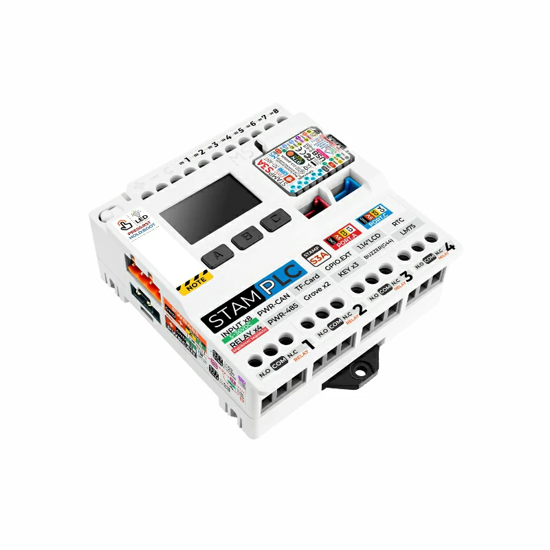
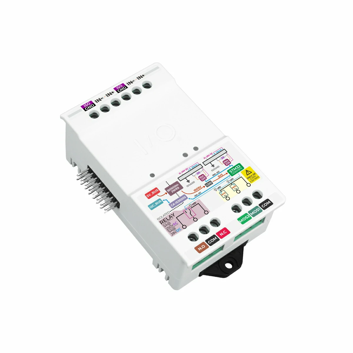
2. 案例程序
- 本教程中使用的主控设备为 StamPLC,搭配 StamPLC IO。StamPLC IO 通过 I2C 的方式与主机通讯,请根据实际的电路连接修改程序中的引脚定义,设备连接后对应的 I2C IO 为
G15 (SCL)、G13 (SDA)。
实物连接组装如下图所示:
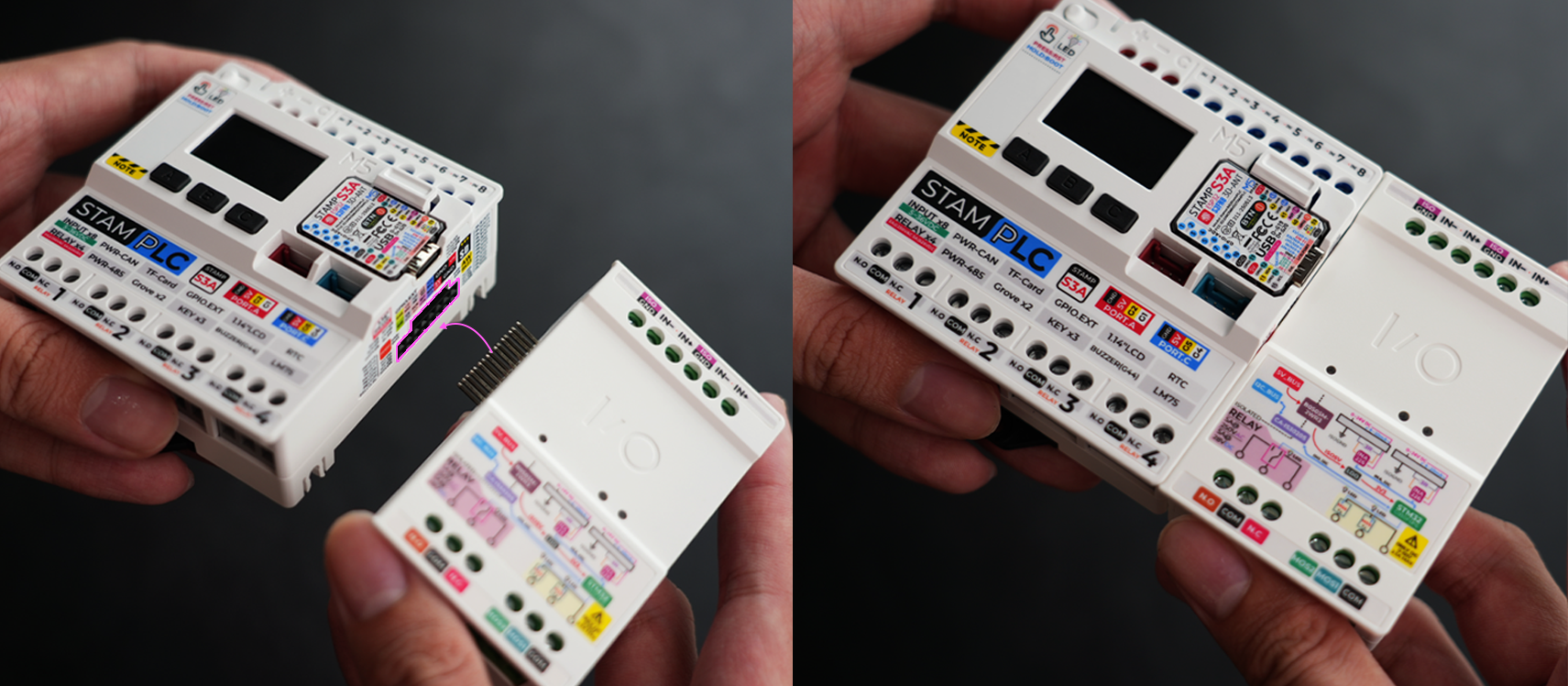
说明
烧录下方程序后,请断电重启设备,以便成功实现相应功能。
电压/电流检测
cpp
1 2 3 4 5 6 7 8 9 10 11 12 13 14 15 16 17 18 19 20 21 22 23 24 25 26 27 28 29 30 31 32 33 34 35 36 37 38 39 40 41 42 43 44 45 46 47 48 49 50 51 52 53 54 55 56 57 58 59 60 61 62 63 64 65 66 67 68 69 70 71 72 73 74 75 76 77 78 79 80 81 82
#include <M5StamPLC.h>

M5Canvas canvas(&M5StamPLC.Display());
M5StamPLC_IO stamplc_io;

constexpr uint32_t MONITOR_UPDATE_INTERVAL_MS = 500;

void setup()
{
    M5StamPLC.begin();
    canvas.createSprite(M5StamPLC.Display().width(), M5StamPLC.Display().height());
    canvas.setTextScroll(false);
    canvas.fillScreen(TFT_BLACK);
    canvas.setTextSize(1);
    canvas.setFont(&fonts::efontCN_16);
    canvas.println("Try to find M5StamPLC IO");

    while (!stamplc_io.begin()) {
        canvas.println("M5StamPLC_IO not found, retry in 1s...");
        canvas.pushSprite(0, 0);
        delay(1000);
    }

    canvas.printf("Found: 0x%02X  FW: 0x%02X\n", stamplc_io.getCurrentAddress(), stamplc_io.getFirmwareVersion());
    canvas.println("Start monitoring...");
    canvas.pushSprite(0, 0);
}

void loop()
{
    M5StamPLC.update();

    static uint32_t last_update = 0;
    bool need_update           = stamplc_io.syncAddress();
    uint32_t now               = millis();

    if (now - last_update >= MONITOR_UPDATE_INTERVAL_MS || need_update) {
        last_update = now;

        int16_t v1, v2;
        int32_t i1, i2;
        stamplc_io.readAllChannelsData(&v1, &i1, &v2, &i2);

        uint8_t io_ctrl    = stamplc_io.readRegister(M5StamPLC_IO::REG_IO_CONTROL);
        uint8_t sys_status = stamplc_io.getSystemStatus();

        canvas.fillScreen(TFT_BLACK);
        canvas.setCursor(0, 0);

        canvas.setTextColor(TFT_GREENYELLOW);
        canvas.println("== Voltage/Current Monitor ==");
        canvas.println();

        canvas.setTextColor(sys_status & (1 << M5StamPLC_IO::SYS_CH1_INA226_ERROR) ? TFT_RED : TFT_GREEN);
        canvas.printf("CH1: %d.%02dV %duA\n", v1 / 1000, abs(v1 % 1000) / 10, i1);

        canvas.setTextColor(sys_status & (1 << M5StamPLC_IO::SYS_CH2_INA226_ERROR) ? TFT_RED : TFT_GREEN);
        canvas.printf("CH2: %d.%02dV %duA\n", v2 / 1000, abs(v2 % 1000) / 10, i2);

        canvas.setTextColor(TFT_YELLOW);
        canvas.printf("Pull-up: CH1=%s CH2=%s\n", (io_ctrl & (1 << M5StamPLC_IO::BIT_CH1_PU_EN)) ? "ON" : "OFF",
                      (io_ctrl & (1 << M5StamPLC_IO::BIT_CH2_PU_EN)) ? "ON" : "OFF");

        canvas.setTextColor(TFT_MAGENTA);
        canvas.printf("Addr: 0x%02X  DIP: 0x%02X\n", stamplc_io.getCurrentAddress(), stamplc_io.getExpectedAddress());

        canvas.setTextColor(sys_status == 0 ? TFT_GREEN : TFT_RED);
        canvas.printf("System: %s\n", sys_status == 0 ? "Normal" : "Error");

        canvas.pushSprite(0, 0);
    }

    if (M5StamPLC.BtnA().wasClicked()) {
        stamplc_io.toggleIOBit(M5StamPLC_IO::BIT_CH1_PU_EN);
        last_update = now - MONITOR_UPDATE_INTERVAL_MS;
    }
    if (M5StamPLC.BtnB().wasClicked()) {
        stamplc_io.toggleIOBit(M5StamPLC_IO::BIT_CH2_PU_EN);
        last_update = now - MONITOR_UPDATE_INTERVAL_MS;
    }
    delay(10);
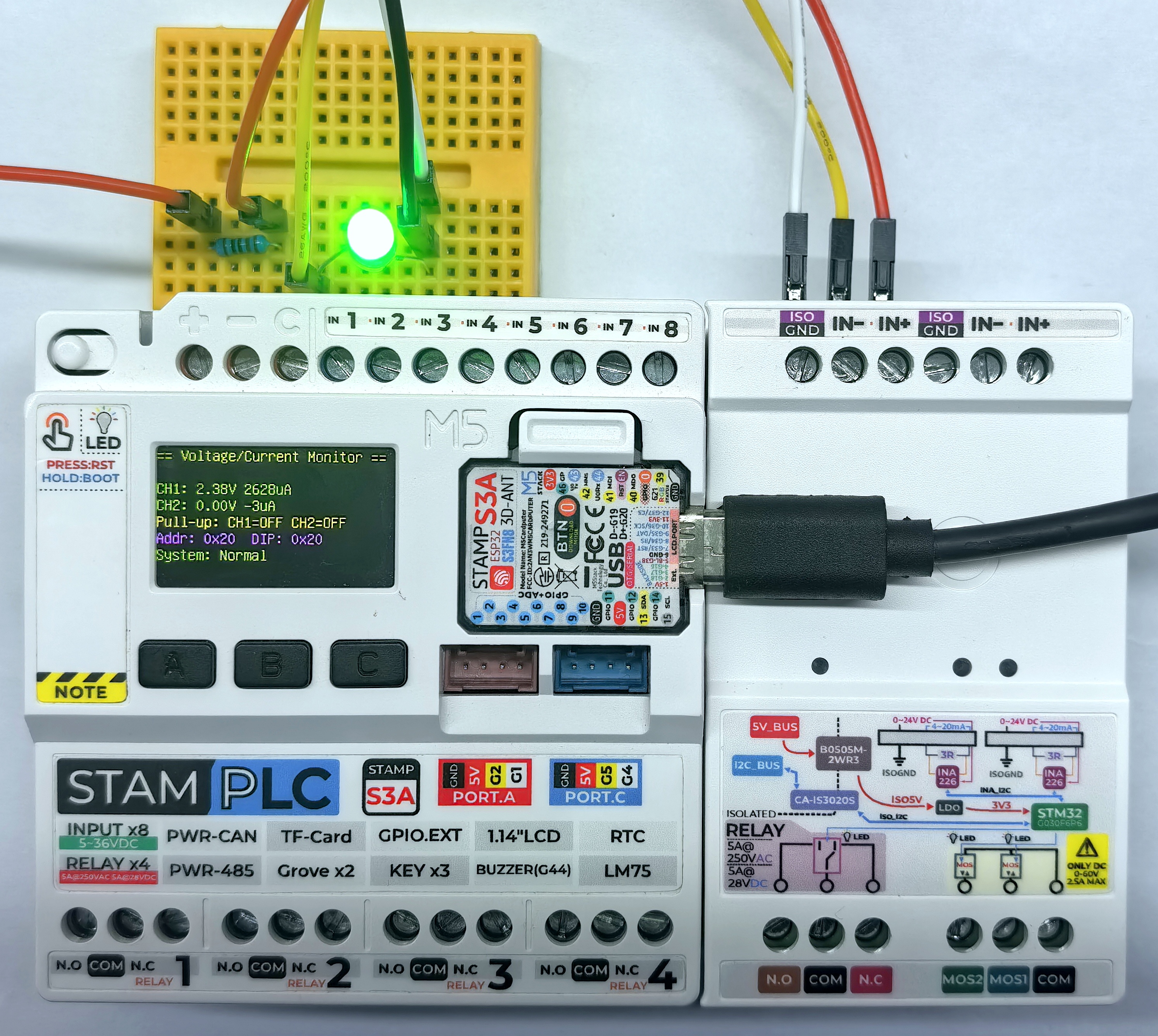
}上电后,StamPLC IO 会自动检测模拟信号的电压和电流值,并在屏幕上显示检测结果。按下 A 键可切换 CH1 的上拉电阻状态,按下 B 键可切换 CH2 的上拉电阻状态,屏幕会实时更新显示当前的上拉电阻状态。
PWM 控制
cpp
1 2 3 4 5 6 7 8 9 10 11 12 13 14 15 16 17 18 19 20 21 22 23 24 25 26 27 28 29 30 31 32 33 34 35 36 37 38 39 40 41 42 43 44 45 46 47 48 49 50 51 52 53 54 55 56 57 58 59 60 61 62 63 64 65 66 67 68 69 70 71 72 73 74 75 76 77 78 79 80 81 82 83 84 85 86 87 88 89 90 91 92 93 94 95 96 97 98 99
#include <M5StamPLC.h>

M5Canvas canvas(&M5StamPLC.Display());
M5StamPLC_IO stamplc_io;

constexpr uint16_t PWM_DUTY_MIN              = 0;
constexpr uint16_t PWM_DUTY_MAX              = 1000;
constexpr uint16_t PWM_DUTY_STEP             = 100;
constexpr uint32_t DUTY_UPDATE_INTERVAL_MS   = 300;

uint8_t pwm_freq          = 50;
uint16_t mos1_duty        = PWM_DUTY_MIN;
uint16_t mos2_duty        = PWM_DUTY_MAX;
int16_t duty_step         = PWM_DUTY_STEP;
uint32_t last_update_time = 0;

void updateDisplay()
{
    canvas.fillScreen(TFT_BLACK);
    canvas.setCursor(0, 0);

    canvas.setTextColor(TFT_GREENYELLOW);
    canvas.println("=== PWM Auto Sweep ===");

    canvas.setTextColor(TFT_CYAN);
    canvas.printf("Mode: PWM  Freq: %dHz\n", pwm_freq);
    canvas.printf("MOS1: %s%d%%  MOS2: %s%d%% /%dms\n", duty_step > 0 ? "+" : "-", PWM_DUTY_STEP / 10,
                  duty_step > 0 ? "-" : "+", PWM_DUTY_STEP / 10, DUTY_UPDATE_INTERVAL_MS);

    canvas.setTextColor(TFT_YELLOW);
    canvas.printf("MOS1: %d.%d%% (%d/1000)\n", mos1_duty / 10, mos1_duty % 10, mos1_duty);
    canvas.printf("MOS2: %d.%d%% (%d/1000)\n", mos2_duty / 10, mos2_duty % 10, mos2_duty);
    canvas.pushSprite(0, 0);
}

void setup()
{
    M5StamPLC.begin();
    canvas.createSprite(M5StamPLC.Display().width(), M5StamPLC.Display().height());
    canvas.setTextScroll(true);
    canvas.fillScreen(TFT_BLACK);
    canvas.setTextSize(1);
    canvas.setFont(&fonts::efontCN_16);
    canvas.println("Try to find M5StamPLC IO module...");
    canvas.pushSprite(0, 0);

    while (!stamplc_io.begin()) {
        canvas.println("Not found, retry in 1s...");
        canvas.pushSprite(0, 0);
        delay(1000);
    }

    canvas.printf("Found: 0x%02X  FW: 0x%02X\n", stamplc_io.getCurrentAddress(), stamplc_io.getFirmwareVersion());
    canvas.pushSprite(0, 0);

    pwm_freq = stamplc_io.getPWMFrequency();
    if (pwm_freq == 0) {
        pwm_freq = 50;
        stamplc_io.setPWMFrequency(pwm_freq);
    }

    stamplc_io.setPWMMode(true);
    stamplc_io.setChannelDuty(1, mos1_duty);
    stamplc_io.setChannelDuty(2, mos2_duty);

    updateDisplay();
}

void loop()
{
    M5StamPLC.update();

    bool needUpdate = stamplc_io.syncAddress();
    uint32_t now    = millis();

    if (now - last_update_time >= DUTY_UPDATE_INTERVAL_MS) {
        last_update_time = now;

        int32_t next_duty = static_cast<int32_t>(mos1_duty) + duty_step;
        if (next_duty >= PWM_DUTY_MAX) {
            next_duty = PWM_DUTY_MAX;
            duty_step = -PWM_DUTY_STEP;
        } else if (next_duty <= PWM_DUTY_MIN) {
            next_duty = PWM_DUTY_MIN;
            duty_step = PWM_DUTY_STEP;
        }

        mos1_duty = static_cast<uint16_t>(next_duty);
        mos2_duty = PWM_DUTY_MAX - mos1_duty;

        stamplc_io.setChannelDuty(1, mos1_duty);
        stamplc_io.setChannelDuty(2, mos2_duty);
        needUpdate = true;
    }

    if (needUpdate) updateDisplay();

    delay(10);
}上电后,MOS1 和 MOS2 的 PWM 输出会按照顺序依次改变占空比,顺序为:MOS1 占空比增加 -> MOS2 占空比减少,对应的输出状态会在屏幕上显示,也可观察到 MOS1 和 MOS2 所连接的 LED 亮度变化。
继电器控制
cpp
1 2 3 4 5 6 7 8 9 10 11 12 13 14 15 16 17 18 19 20 21 22 23 24 25 26 27 28 29 30 31 32 33 34 35 36 37 38 39 40 41 42 43 44 45 46 47 48 49 50 51 52 53 54 55 56 57 58 59 60 61 62 63 64 65 66 67 68 69 70 71 72 73 74 75 76 77 78 79 80 81 82 83 84 85 86 87 88 89 90 91 92 93 94 95 96 97 98 99 100 101 102 103
#include <M5StamPLC.h>

M5Canvas canvas(&M5StamPLC.Display());
M5StamPLC_IO stamplc_io;

constexpr uint32_t OUTPUT_UPDATE_INTERVAL_MS = 500;
constexpr uint8_t OUTPUT_COUNT               = 3;

const uint8_t output_bits[OUTPUT_COUNT] = {
    M5StamPLC_IO::BIT_RELAY_TRIG,
    M5StamPLC_IO::BIT_EX_CTR_1,
    M5StamPLC_IO::BIT_EX_CTR_2,
};

const char* output_names[OUTPUT_COUNT] = {"Relay", "MOS1", "MOS2"};

bool output_state[OUTPUT_COUNT] = {false, false, false};
uint8_t output_step             = 0;
uint32_t last_update_time       = 0;
uint8_t last_output_index       = 0;
bool last_output_state          = false;
bool last_output_valid          = false;

void updateDisplay()
{
    canvas.fillScreen(TFT_BLACK);
    canvas.setCursor(0, 0);

    canvas.setTextColor(TFT_GREENYELLOW);
    canvas.println("=== Output Auto Sequence ===");

    canvas.setTextColor(TFT_CYAN);
    canvas.printf("Addr: 0x%02X\n", stamplc_io.getCurrentAddress());
    canvas.println("Order: Relay -> MOS1 -> MOS2");
    canvas.printf("Interval: %lums\n", static_cast<unsigned long>(OUTPUT_UPDATE_INTERVAL_MS));

    for (uint8_t i = 0; i < OUTPUT_COUNT; i++) {
        canvas.setTextColor(output_state[i] ? TFT_GREEN : TFT_RED);
        canvas.printf("%s: %s\n", output_names[i], output_state[i] ? "ON" : "OFF");
    }

    if (last_output_valid) {
        canvas.setTextColor(TFT_YELLOW);
        canvas.printf("Last: %s -> %s\n", output_names[last_output_index], last_output_state ? "ON" : "OFF");
    }

    canvas.pushSprite(0, 0);
}

void setOutputState(uint8_t index, bool state)
{
    output_state[index] = state;
    stamplc_io.setRelayState(output_bits[index], state);
    last_output_index  = index;
    last_output_state  = state;
    last_output_valid  = true;
    updateDisplay();
}

void setup()
{
    /* Init M5StamPLC*/
    M5StamPLC.begin();
    canvas.createSprite(M5StamPLC.Display().width(), M5StamPLC.Display().height());
    canvas.setTextScroll(false);
    canvas.fillScreen(TFT_BLACK);
    canvas.setTextSize(1);
    canvas.setFont(&fonts::efontCN_16);
    canvas.println("Try to find M5StamPLC IO");
    canvas.pushSprite(0, 0);

    /* Init M5StamPLC IO */
    while (!stamplc_io.begin()) {
        canvas.println("M5StamPLC_IO not found, retry in 1s...");
        canvas.pushSprite(0, 0);
        delay(1000);
    }

    for (uint8_t i = 0; i < OUTPUT_COUNT; i++) {
        setOutputState(i, false);
    }
}

void loop()
{
    M5StamPLC.update();

    if (stamplc_io.syncAddress()) {
        updateDisplay();
    }

    uint32_t now = millis();
    if (now - last_update_time >= OUTPUT_UPDATE_INTERVAL_MS) {
        last_update_time = now;

        uint8_t output_index = output_step % OUTPUT_COUNT;
        bool state           = output_step < OUTPUT_COUNT;
        setOutputState(output_index, state);
        output_step = (output_step + 1) % (OUTPUT_COUNT * 2);
    }

    delay(10);
}上电后,继电器输出会按照顺序依次打开和关闭,顺序为:继电器 -> MOS1 -> MOS2,对应的输出状态会在屏幕上显示,也可观察到继电器的指示灯及继电器所连接的负载状态变化。
继电器:
MOS1、 MOS2:
3.编译上传
- 长按 StamPLC 上的 Boot 按键, 等待红灯亮起后松开按键。松开后红灯熄灭,表示设备已进入下载模式,等待烧录。
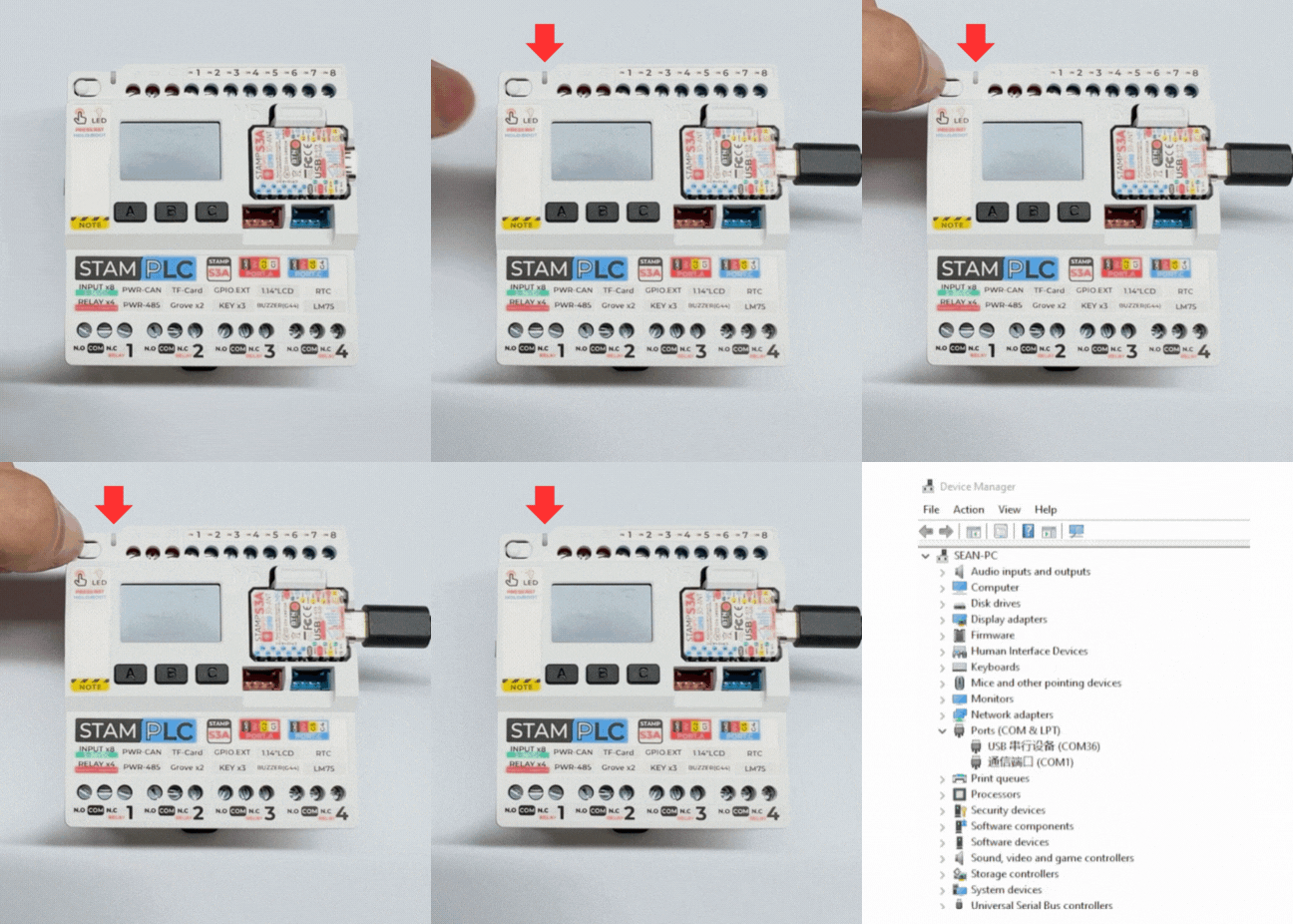
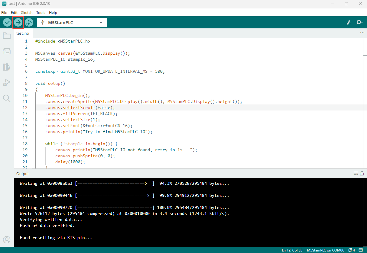
- 选中设备端口,选择上述案例程序粘贴,点击 Arduino IDE 左上角编译上传按钮,等待程序完成编译并上传至设备。
Page Tools