

Arduino Quick Start
2. Devices & Examples
3. M5Unified
4. M5GFX
5. Extensions
Unit
Module
Atomic
Tab5
IoT
Accessories
Chain Buzzer Tutorial
1. Preparation
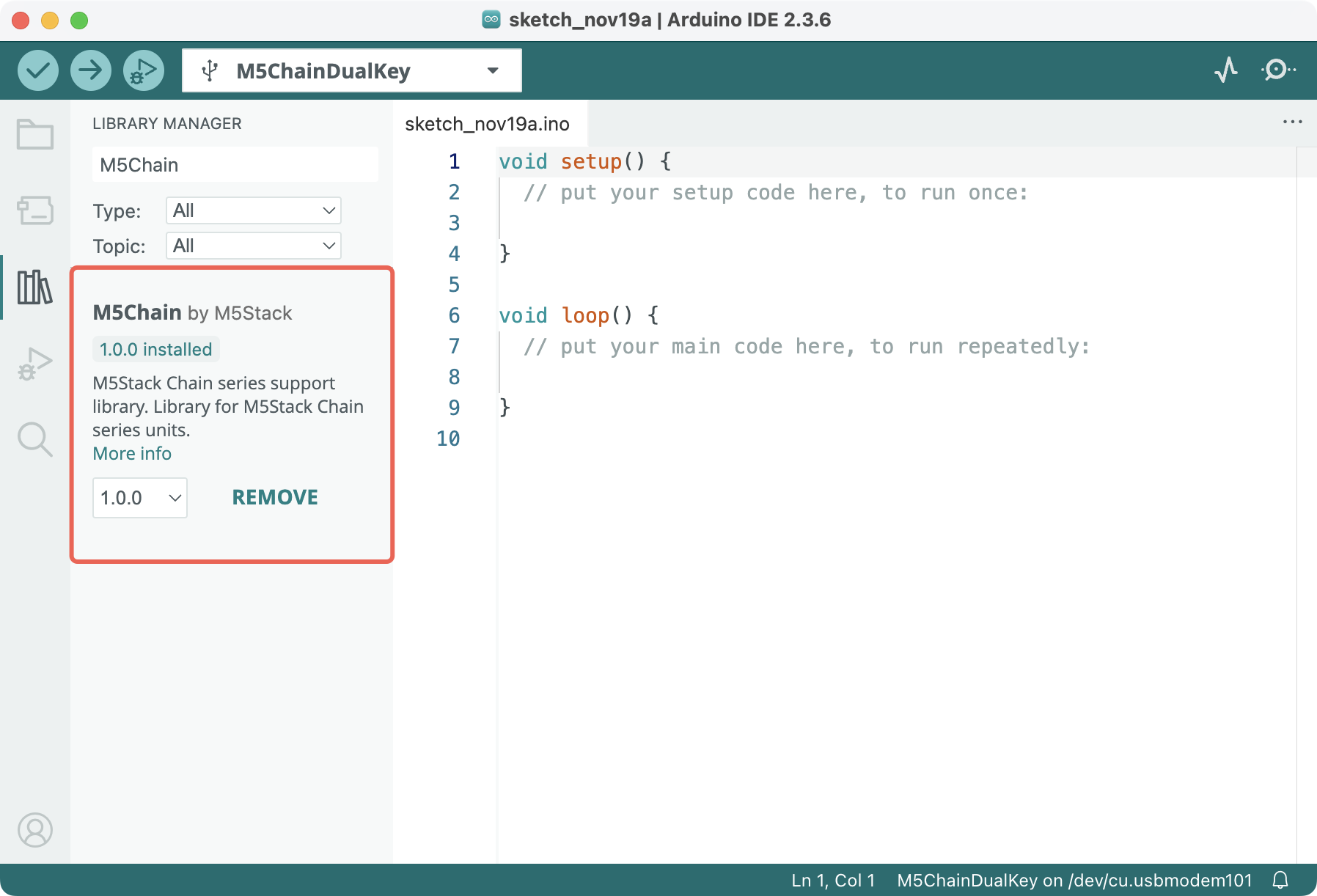
Environment setup: Follow the Arduino IDE Getting Started Tutorial to install the IDE, then install the appropriate board package and required driver libraries for the development board you are using.
Required driver library:
- Required hardware:
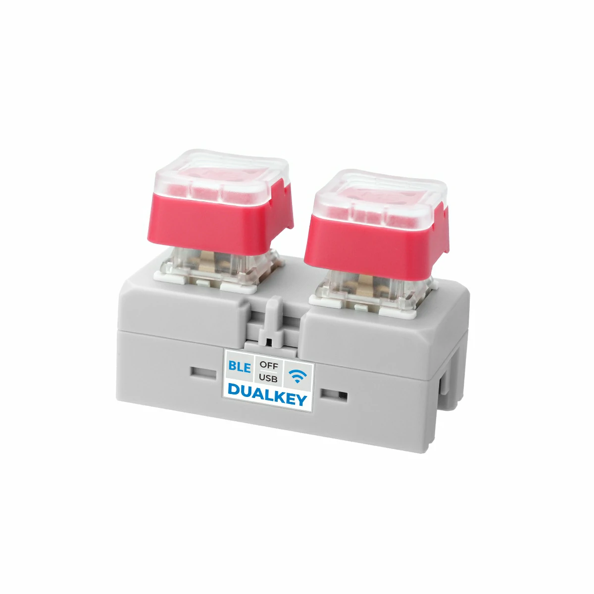
- Chain DualKey
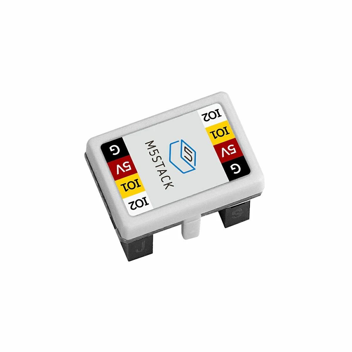
- A Chain series connector, such as Chain Bridge or Chain Return
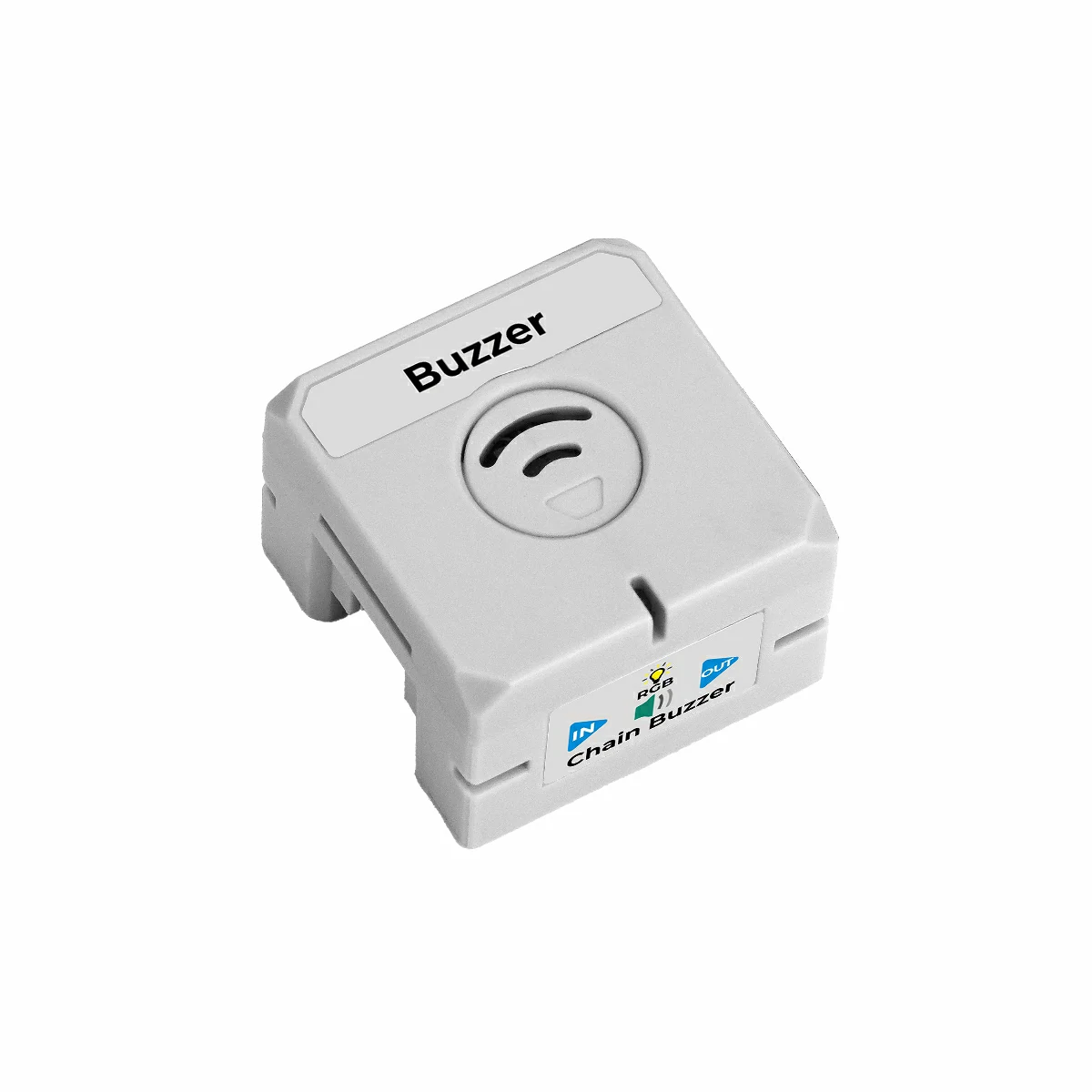
- Chain Buzzer
2. Example Program
M5Chain library version >= 1.0.8
#include "M5Chain.h"

#define RXD_PIN GPIO_NUM_5  // 47 for the other side of Chain DualKey
#define TXD_PIN GPIO_NUM_6  // 48 for the other side of Chain DualKey

Chain M5Chain;

device_list_t *device_list = NULL;
uint16_t device_count = 0;
uint8_t opr_status = 0;

uint8_t buzzer_id = 0;
bool buzzer_found = false;

void setup() {
  Serial.begin(115200);
  delay(1000);
  Serial.println("===========================");
  Serial.println("M5Stack Chain Buzzer Test");

  M5Chain.begin(&Serial2, 115200, RXD_PIN, TXD_PIN);
  while (!M5Chain.isDeviceConnected()) {
    Serial.println("No device connected");
    delay(1000);
  }

  M5Chain.getDeviceNum(&device_count);
  device_list = (device_list_t *)malloc(sizeof(device_list_t));
  device_list->count = device_count;
  device_list->devices = (device_info_t *)malloc(sizeof(device_info_t) * device_count);
  M5Chain.getDeviceList(device_list);

  for (uint16_t i = 0; i < device_count; i++) {
    if (device_list->devices[i].device_type == CHAIN_BUZZER_TYPE_CODE) {
      buzzer_id = device_list->devices[i].id;
      buzzer_found = true;
      Serial.printf("ID[%d] is Chain Buzzer\n", buzzer_id);
      break;
    }
  }

  if (!buzzer_found) {
    Serial.println("Chain Buzzer not found");
    return;
  }

  // Device ID, RGB brightness (0-100), operation status pointer
  M5Chain.setRGBLight(buzzer_id, 50, &opr_status);
  // Device ID, buzzer mode, operation status pointer
  M5Chain.setBuzzerMode(buzzer_id, BUZZER_MODE_AUTO_PLAY, &opr_status);
}

void loop() {
  if (!buzzer_found) {
    delay(1000);
    return;
  }

  uint8_t red[] = {255, 0, 0};
  M5Chain.setRGBValue(buzzer_id, 0, 1, red, sizeof(red), &opr_status);
  // Device ID, frequency (100-10000 Hz), duty (0-100%), duration (ms),
  // operation status pointer
  M5Chain.setBuzzerAutoPlay(buzzer_id, 1000, 50, 500, &opr_status);
  Serial.println("Buzzer: 1000 Hz, 50%, 500 ms");
  delay(1000);

  uint8_t blue[] = {0, 0, 255};
  M5Chain.setRGBValue(buzzer_id, 0, 1, blue, sizeof(blue), &opr_status);
  M5Chain.setBuzzerAutoPlay(buzzer_id, 2000, 50, 500, &opr_status);
  Serial.println("Buzzer: 2000 Hz, 50%, 500 ms");
  delay(1000);
}Use a Chain Bridge connector to connect the Chain DualKey controller to the Chain Buzzer. Pay attention to the orientation: the triangular arrow should point outward from the Chain DualKey, as shown below:
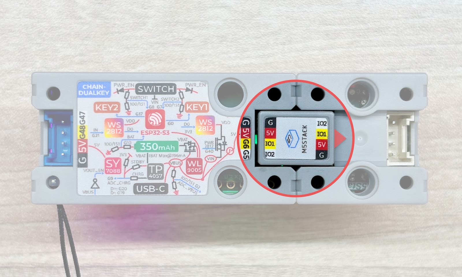
TXD_PIN = GPIO_NUM_6 (GPIO6)
This example uses GPIO5 on the Chain DualKey as RX and GPIO6 as TX. If the Chain Buzzer is connected to the port on the other side of the Chain DualKey, or if a different controller is used, modify RXD_PIN and TXD_PIN in the program according to the actual wiring.
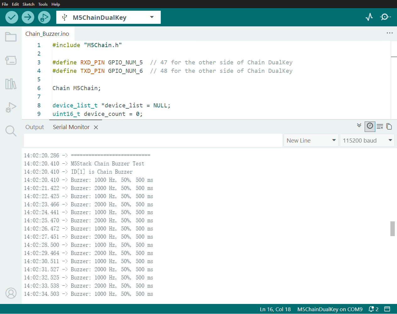
Compile and upload the program to the device, then click the button in the upper-right corner of the Arduino IDE to open the Serial Monitor. The monitor displays the current buzzer frequency, duty cycle, and duration. The Chain Buzzer switches between red and blue while alternately playing 1000 Hz and 2000 Hz tones:
The example operates as follows: