

Arduino Quick Start
2. Devices & Examples
3. M5Unified
4. M5GFX
5. Extensions
Unit
Atomic
Tab5
IoT
Accessories
Module13.2 PPS Arduino Tutorial
1. Preparation
- Environment Setup: Refer to the Arduino IDE Getting Started Guide to install the IDE, then install the corresponding board package and drivers for the host device you are using.
- Required Driver Libraries:
- Hardware Products Used:
- CoreS3
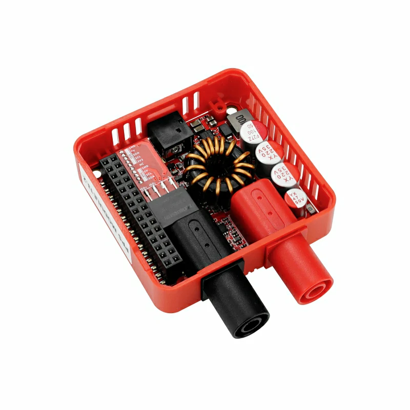
- Module13.2 PPS
- DC 9 ~ 36V External Power Supply

2. Precautions
External Power Supply
Module13.2 PPS must be connected to a DC 9 ~ 36V external power supply. Otherwise, the module will not operate properly, and the host display will show
No i2c device. The actual maximum output capability depends on the input power supply, load, and current-carrying capacity of the connecting cables.Pin Compatibility
Because pin configurations vary between host devices, refer to the Pin Compatibility Table in the product documentation before use and modify the example program according to the actual pin connections.
3. Example Program
- This tutorial uses CoreS3 with Module13.2 PPS for adjustable power supply control. Module13.2 PPS communicates via I2C. Modify the pin definitions in the program according to the actual circuit connections. After connecting the devices, the corresponding I2C IO pins are
G12 (SDA)andG11 (SCL).
cpp
1 2 3 4 5 6 7 8 9 10 11 12 13 14 15 16 17 18 19 20 21 22 23 24 25 26 27 28 29 30 31 32 33 34 35 36 37 38 39 40 41 42 43 44 45 46 47 48 49 50 51 52 53 54 55 56 57 58 59 60 61 62 63 64 65 66 67 68 69 70 71 72 73 74 75 76 77 78 79 80 81 82 83 84 85 86 87 88
#include <M5Unified.h>
#include <M5GFX.h>
#include "M5ModulePPS.h"

M5GFX display;
M5Canvas canvas(&display);
M5ModulePPS pps;

// PPS output voltage target and current limit.
#define OUTPUT_VOLTAGE 5.0f
#define OUTPUT_CURRENT 5.0f

void setup() {
    M5.begin();
    display.begin();

    // Create a full-screen canvas for flicker-free updates.
    canvas.setFont(&fonts::FreeMonoBoldOblique12pt7b);
    canvas.createSprite(display.width(), display.height());

    // Retry until the PPS responds on the CoreS3 internal I2C bus.
    while (!pps.begin(&Wire, M5.In_I2C.getSDA(), M5.In_I2C.getSCL(),
                      MODULE_POWER_ADDR, 400000U)) {
        Serial.println("module pps connect error");
        canvas.clear(BLACK);
        canvas.setTextColor(RED);
        canvas.drawCenterString("No i2c device", display.width() / 2,
                                display.height() / 2);
        canvas.pushSprite(0, 0);
        delay(100);
    }

    // Apply both setpoints before enabling the power output.
    pps.setOutputVoltage(OUTPUT_VOLTAGE);
    pps.setOutputCurrent(OUTPUT_CURRENT);
    pps.setPowerEnable(true);
}

void loop() {
    // Read the live input, output, temperature, and regulation state.
    float voltage_readback = pps.getReadbackVoltage();
    float current_readback = pps.getReadbackCurrent();
    float temperature      = pps.getTemperature();
    float vin              = pps.getVIN();
    uint8_t mode           = pps.getMode();

    // Render one complete status frame before updating the display.
    canvas.fillSprite(BLACK);
    canvas.setFont(&fonts::FreeMonoBold12pt7b);
    canvas.setTextColor(WHITE);
    canvas.drawCenterString("Module PPS", display.width() / 2, 0);

    canvas.setCursor(10, 40);
    canvas.setTextColor(WHITE);
    canvas.printf("VIN: ");
    canvas.setTextColor(GREEN);
    canvas.printf("%.2fV", vin);

    canvas.setCursor(10, 80);
    canvas.setTextColor(WHITE);
    canvas.printf("Mode: ");
    canvas.setTextColor(GREEN);
    // The PPS switches between CV and CC automatically as the load changes.
    if (mode <= 1)
        canvas.printf("Constant Voltage");
    else
        canvas.printf("Constant Current");

    canvas.setTextColor(WHITE);
    canvas.setCursor(10, 120);
    canvas.printf("Voltage: ");
    canvas.setTextColor(GREEN);
    canvas.printf("%.2fV", voltage_readback);

    canvas.setCursor(10, 160);
    canvas.setTextColor(WHITE);
    canvas.printf("Current: ");
    canvas.setTextColor(GREEN);
    canvas.printf("%.2fA", current_readback);

    canvas.setCursor(10, 200);
    canvas.setTextColor(WHITE);
    canvas.printf("Temperature: ");
    canvas.setTextColor(GREEN);
    canvas.printf("%.2fC", temperature);

    canvas.pushSprite(0, 0);
}4. Compile and Upload
- 1. Enter Download Mode: Press and hold the CoreS3 reset button (for about 2 seconds) until the internal green LED lights up, then release it. The device is now in download mode and ready for flashing.
Note
Different devices need to enter download mode before flashing, and the procedure may vary depending on the host device. For details, refer to the list of device flashing tutorials at the bottom of the Arduino IDE Getting Started Guide page.
.gif)
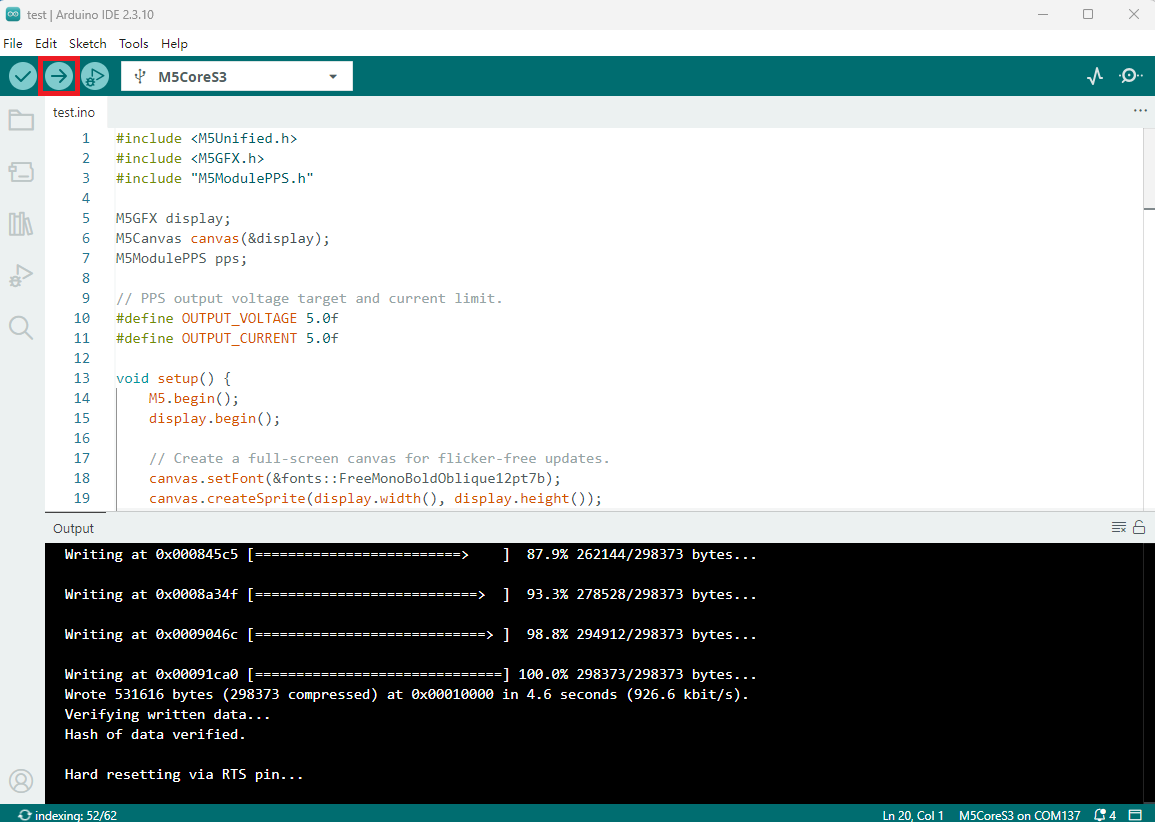
- Select the device port, click the Compile and Upload button in the upper-left corner of Arduino IDE, and wait for the program to finish compiling and uploading to the device.
5. Function Verification
- After power-on, CoreS3 initializes Module13.2 PPS, sets the output voltage to 5.0V and the current limit to 5.0A, enables the output, and then continuously displays the input voltage, CV/CC mode, output voltage, output current, and module temperature on the screen.
Note
The PPS module automatically switches operating states according to the load. It operates in constant-voltage mode (
Constant Voltage) when the load current is below the current limit. If the load attempts to exceed the current limit, the module reduces the output voltage and enters constant-current mode (Constant Current). getMode() only reads the current state; it does not switch modes manually.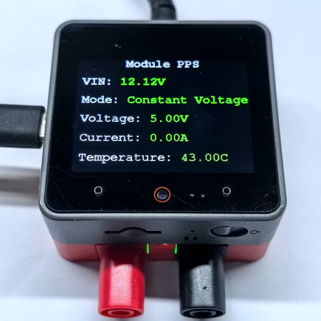
Page Tools