

Arduino Quick Start
2. Devices & Examples
3. M5Unified
4. M5GFX
5. Extensions
Unit
Module
Atomic
Tab5
IoT
Accessories
Module13.2 Servo2 Arduino Tutorial
1. Preparation
Environment Setup: Refer to the Arduino IDE Getting Started Guide to install the IDE, then install the board package for the development board you are using and the required driver libraries.
Required Driver Libraries:
Hardware Products Used:

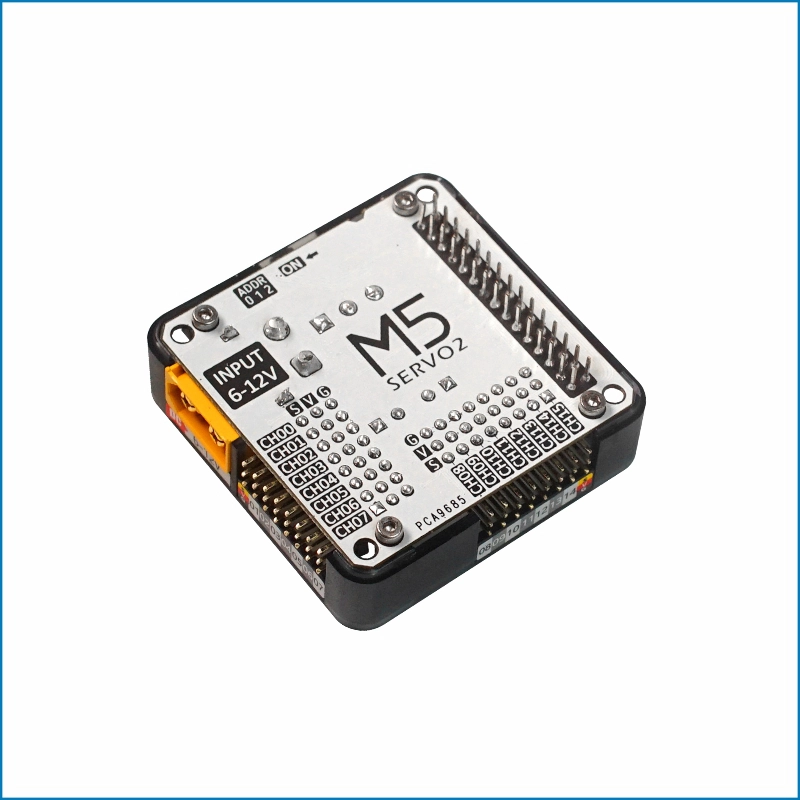
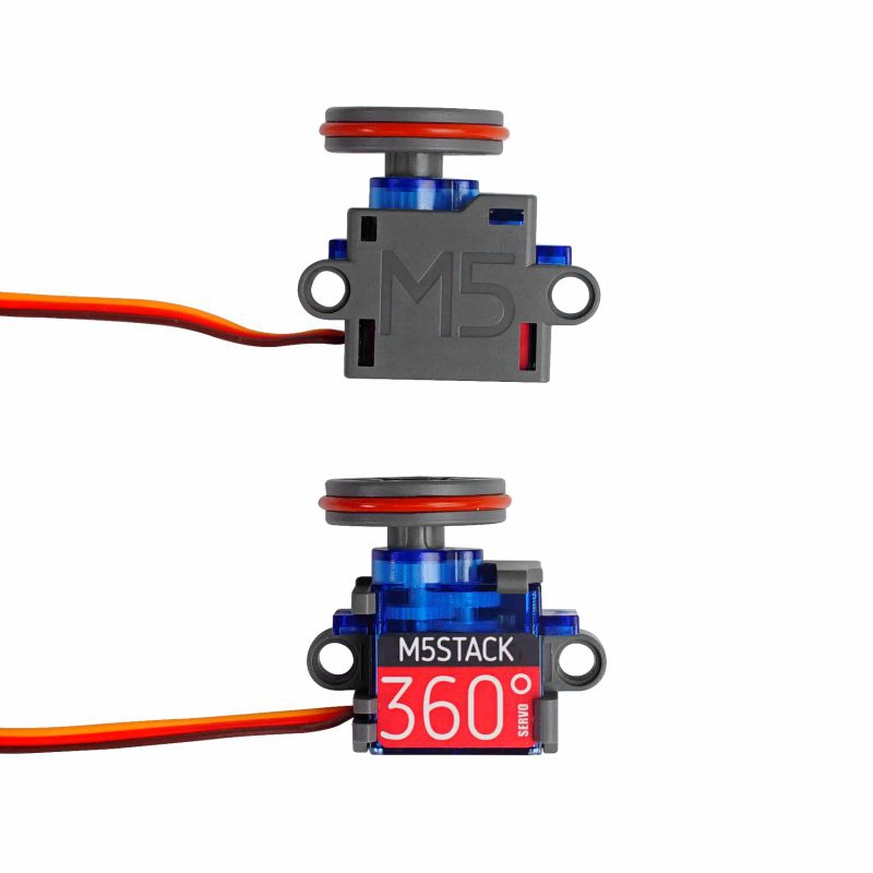
2. Precautions
Pin Compatibility
Because pin configurations vary between host devices, refer to the Pin Compatibility Table in the product documentation before use and modify the example program according to the actual pin connections.
3. Example Program
- This tutorial uses CoreS3 with Module13.2 Servo2 to control servos. Module13.2 Servo2 communicates via I2C. Modify the pin definitions in the program according to the actual circuit connections. After connecting the devices, the corresponding I2C IO pins are
G12 (SDA)andG11 (SCL).
3.1 Multi-Channel Control
cpp
1 2 3 4 5 6 7 8 9 10 11 12 13 14 15 16 17 18 19 20 21 22 23 24 25 26 27 28 29 30 31 32 33 34 35 36 37 38 39 40 41 42 43 44 45 46 47 48 49 50 51 52 53 54 55 56 57 58 59 60 61 62 63 64 65 66 67 68 69 70 71 72 73 74 75 76 77 78 79 80 81 82 83 84 85 86 87 88 89 90 91 92 93 94 95
#include <M5Unified.h>
#include <Wire.h>
#include "Adafruit_PWMServoDriver.h"

#define SERVO_FREQ 50  // Servo PWM frequency.
#define SERVO2_I2C_ADDRESS 0x41

Adafruit_PWMServoDriver* pwm = nullptr;

void setup()
{
    auto cfg = M5.config();
    M5.begin(cfg);
    M5.Lcd.setFont(&fonts::FreeMonoBold12pt7b);
    Serial.begin(115200);

    // Get M5Bus I2C pins.
    const int8_t wireSda = M5.getPin(m5::pin_name_t::in_i2c_sda);
    const int8_t wireScl = M5.getPin(m5::pin_name_t::in_i2c_scl);

    // Find the configured SERVO2 address.
    Serial.printf("Scanning SERVO2 address 0x%02X...\n", SERVO2_I2C_ADDRESS);
    if (M5.In_I2C.scanID(SERVO2_I2C_ADDRESS)) {
        Serial.printf("Found PCA9685 at 0x%02X\n", SERVO2_I2C_ADDRESS);
    } else {
        Serial.println("PCA9685 not found on M5Bus");
        M5.Display.drawString("PCA9685 not found", 10, 80);
        while (true) {
            delay(1000);
        }
    }

    Wire.setPins(wireSda, wireScl);
    pwm = new Adafruit_PWMServoDriver(SERVO2_I2C_ADDRESS, Wire);

    if (!pwm->begin()) {
        Serial.printf("Wire could not initialize PCA9685 at 0x%02X\n", SERVO2_I2C_ADDRESS);
        M5.Display.drawString("Wire init failed", 10, 80);
        while (true) {
            delay(1000);
        }
    }

    // Set the PWM frequency for analog servos.
    pwm->setPWMFreq(SERVO_FREQ);

    M5.Lcd.setTextColor(TFT_GREEN, TFT_BLACK);
    M5.Lcd.drawCenterString("Module13.2 Servo2 Test", 160, 10);
}

// Set one PCA9685 channel using a pulse width in milliseconds.
void setServoPulse(uint8_t n, double pulse)
{
    double pulselength;

    // Calculate the PWM period in microseconds.
    pulselength = 1000000;
    pulselength /= SERVO_FREQ;

    // Print the period for debugging.
    Serial.print(pulselength);
    Serial.println(" us per period");

    // Convert the period to one 12-bit PWM step.
    pulselength /= 4096;
    Serial.print(pulselength);
    Serial.println(" us per bit");

    // Convert the pulse width from milliseconds to PWM steps.
    pulse *= 1000;
    pulse /= pulselength;
    Serial.println(pulse);

    // Output the requested high pulse.
    pwm->setPWM(n, 0, pulse);
}

void loop()
{
    // Drive all channels with a 0.5 ms pulse.
    for (int i = 0; i < 16; i++) {
        setServoPulse(i, 0.5);
    }
    M5.Lcd.fillRect(0, 70, 320, 20, TFT_BLACK);
    M5.Lcd.drawCenterString("Pulse width: 0.5 ms", 160, 80);
    delay(1000);

    // Drive all channels with a 2.5 ms pulse.
    for (int i = 0; i < 16; i++) {
        setServoPulse(i, 2.5);
    }
    M5.Lcd.fillRect(0, 70, 320, 20, TFT_BLACK);
    M5.Lcd.drawCenterString("Pulse width: 2.5 ms", 160, 80);
    delay(1000);
}3.2 ALL_CALL Configuration
I2C Address Conflict
The onboard PCA9685 chip of Module13.2 Servo2 has the ALL_CALL broadcast address
0x70 enabled by default for synchronizing multiple chips. After power-on, the module responds not only to requests sent to its own I2C communication address (0x40 ~ 0x47), but also to the ALL_CALL I2C address 0x70. If a device with the same address is connected to the current I2C bus, an address conflict will occur and communication may fail. This can be resolved by configuring the ALLCALL bit (bit:0) in the PCA9685 MODE1 register (0x00H) to 0 to disable the ALL_CALL function.cpp
1 2 3 4 5 6 7 8 9 10 11 12 13 14 15 16 17 18 19 20 21 22 23 24 25 26 27 28 29 30 31 32 33 34 35 36 37 38 39 40 41 42 43 44 45 46 47 48 49 50 51 52 53 54 55 56 57 58 59 60 61 62 63 64 65 66 67 68 69 70 71 72 73 74 75 76 77 78 79 80 81 82 83 84 85 86 87 88 89 90 91 92 93 94 95 96 97 98 99 100 101 102 103 104 105 106 107 108 109 110 111 112 113 114 115 116 117 118 119
#include <M5Unified.h>
#include <Wire.h>

#define SERVO2_I2C_ADDRESS 0x41

constexpr uint8_t PCA9685_MODE1_REG = 0x00;
constexpr uint8_t PCA9685_ALLCALL_BIT = 0x01;

bool readRegister8(uint8_t address, uint8_t reg, uint8_t &value)
{
    Wire.beginTransmission(address);
    Wire.write(reg);

    if (Wire.endTransmission(false) != 0) {
        return false;
    }

    if (Wire.requestFrom(address, static_cast<uint8_t>(1)) != 1) {
        return false;
    }

    value = Wire.read();
    return true;
}

bool writeRegister8(uint8_t address, uint8_t reg, uint8_t value)
{
    Wire.beginTransmission(address);
    Wire.write(reg);
    Wire.write(value);
    return Wire.endTransmission(true) == 0;
}

bool setAllCall(uint8_t address, bool enable)
{
    uint8_t mode1 = 0;

    if (!readRegister8(address, PCA9685_MODE1_REG, mode1)) {
        return false;
    }

    // Set or clear MODE1 bit 0 and preserve the other MODE1 bits.
    if (enable) {
        mode1 |= PCA9685_ALLCALL_BIT;
    } else {
        mode1 &= static_cast<uint8_t>(~PCA9685_ALLCALL_BIT);
    }
    return writeRegister8(address, PCA9685_MODE1_REG, mode1);
}

bool probeI2C(uint8_t address)
{
    Wire.beginTransmission(address);
    return Wire.endTransmission(true) == 0;
}

void setup()
{
    auto cfg = M5.config();
    M5.begin(cfg);

    Serial.begin(115200);
    delay(500);

    const int8_t wireSda = M5.getPin(m5::pin_name_t::in_i2c_sda);
    const int8_t wireScl = M5.getPin(m5::pin_name_t::in_i2c_scl);
    Wire.setPins(wireSda, wireScl);
    Wire.begin();

    if (!probeI2C(SERVO2_I2C_ADDRESS)) {
        Serial.printf("PCA9685 not found at 0x%02X\n", SERVO2_I2C_ADDRESS);
        while (true) {
            delay(1000);
        }
    }

    // Enable ALL_CALL and test the 0x70 address.
    if (setAllCall(SERVO2_I2C_ADDRESS, true)) {
        uint8_t mode1 = 0;
        if (readRegister8(SERVO2_I2C_ADDRESS, PCA9685_MODE1_REG, mode1)) {
            Serial.printf("ALL_CALL enabled, MODE1: 0x%02X\n", mode1);
        } else {
            Serial.println("ALL_CALL enabled, but MODE1 readback failed");
        }
    } else {
        Serial.println("Failed to enable ALL_CALL");
    }

    Serial.println("Test 0x70 with ALL_CALL enabled:");
    if (probeI2C(0x70)) {
        Serial.println("0x70: ACK");
    } else {
        Serial.println("0x70: NACK");
    }

    // Disable ALL_CALL and test the 0x70 address again.
    if (setAllCall(SERVO2_I2C_ADDRESS, false)) {
        uint8_t mode1 = 0;
        if (readRegister8(SERVO2_I2C_ADDRESS, PCA9685_MODE1_REG, mode1)) {
            Serial.printf("ALL_CALL disabled, MODE1: 0x%02X\n", mode1);
        } else {
            Serial.println("ALL_CALL disabled, but MODE1 readback failed");
        }
    } else {
        Serial.println("Failed to disable ALL_CALL");
    }

    Serial.println("Test 0x70 with ALL_CALL disabled:");
    if (probeI2C(0x70)) {
        Serial.println("0x70: ACK");
    } else {
        Serial.println("0x70: NACK");
    }
}

void loop()
{
    delay(1000);
}Serial output example:
ALL_CALL disabled
MODE1: 0x20
0x70: NACK
ALL_CALL enabled, MODE1: 0x21
Test 0x70 with ALL_CALL enabled:
0x70: ACK
ALL_CALL disabled, MODE1: 0x20
Test 0x70 with ALL_CALL disabled:
0x70: NACK4. Compile and Upload
- 1. Enter Download Mode: Press and hold the CoreS3 reset button (for about 2 seconds) until the internal green LED lights up, then release it. The device is now in download mode and ready for flashing. The green LED turns off after the button is released, confirming that the device is in download mode.
Note
Different devices need to enter download mode before flashing, and the procedure may vary depending on the main controller. For details, refer to the list of device flashing tutorials at the bottom of the Arduino IDE Getting Started Guide page.
.gif)
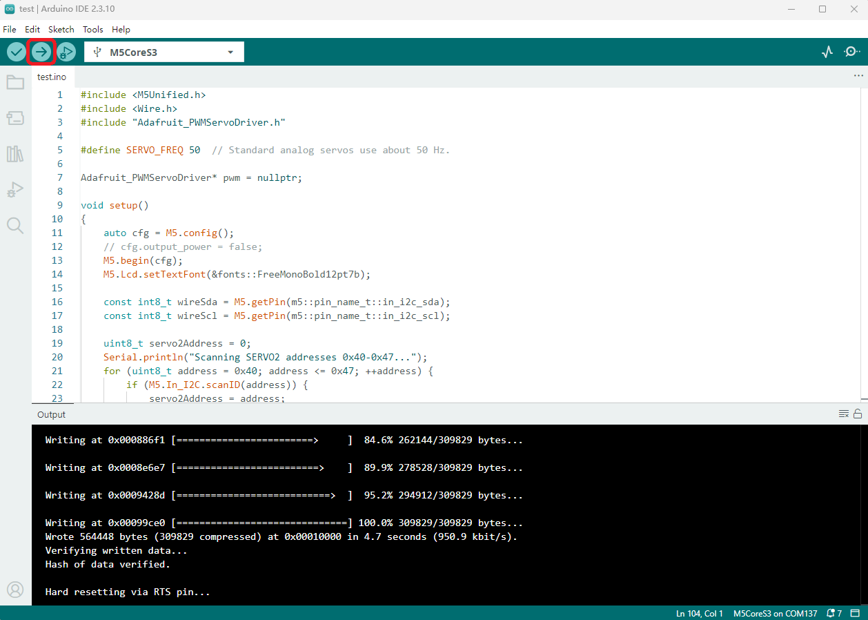
- 2. Select the device port, click the Compile and Upload button in the upper-left corner of Arduino IDE, and wait for the program to finish compiling and uploading to the device.
5. Servo Control
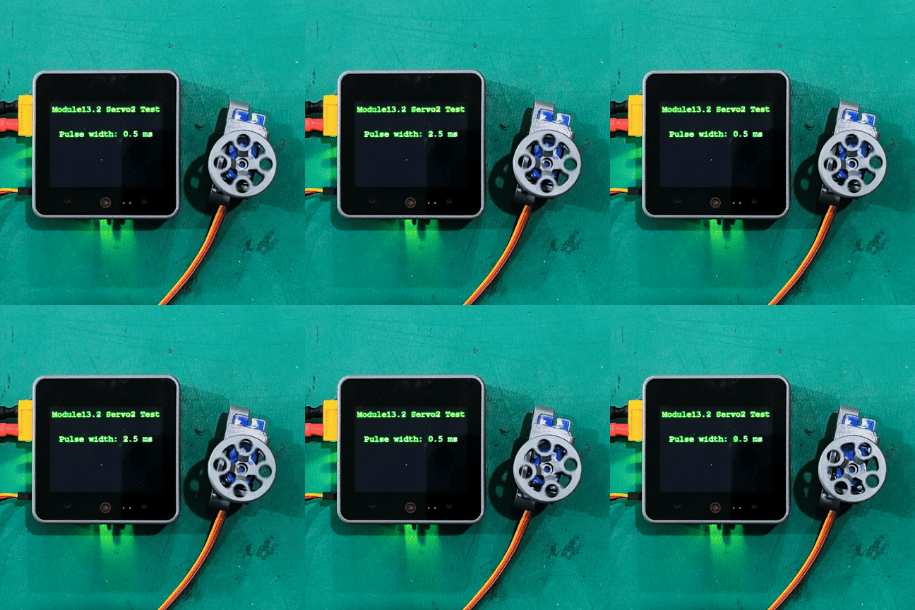
- After power-on, the Module13.2 Servo2 module is initialized automatically, then the servos are driven repeatedly using pulse widths of 0.5ms / 2.5ms.
Note
The example code drives all 16 channels; only one channel is connected to a servo in the image below for demonstration.
Page Tools