

Arduino Quick Start
2. Devices & Examples
3. M5Unified
4. M5GFX
5. Extensions
Unit
Module
Atomic
Tab5
IoT
Accessories
Unit Buzzer Arduino Tutorial
1. Preparations
- Environment Setup: Refer to the Arduino IDE Getting Started Guide to complete IDE installation, and install the corresponding board manager and required driver libraries for the development board used.
- Required Driver Libraries:
- Required Hardware Products:

2. Notes
Pin Compatibility
Since pin configurations vary across host devices, M5Stack provides a pin compatibility table for reference. Modify the example program according to your actual pin connections.
3. Example Program
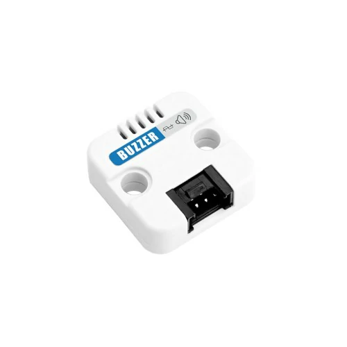
- This tutorial uses a CoreS3 as the main controller with a Unit Buzzer. The Unit Buzzer is a passive buzzer driven by a PWM signal, and its corresponding pin after connection is
G9.
cpp
1 2 3 4 5 6 7 8 9 10 11 12 13 14 15 16 17 18 19 20 21 22 23 24 25 26 27 28 29 30 31 32 33 34 35 36 37 38 39 40 41 42 43 44 45 46 47 48 49 50 51 52 53 54 55 56 57 58 59 60 61 62 63 64 65 66
#include <M5Unified.h>

constexpr uint8_t buzzer_pin = 9;
constexpr uint32_t freq = 4000;
constexpr uint8_t resolution = 10;

uint32_t beepCount = 0;

void showStatus(const char* status, uint32_t duty) {
  // Draw the current PWM state on the display.
  M5.Display.clear();
  M5.Display.setTextSize(2);

  M5.Display.setCursor(10, 20);
  M5.Display.println("LEDC Buzzer");

  M5.Display.setCursor(10, 60);
  M5.Display.printf("Pin: %u", buzzer_pin);

  M5.Display.setCursor(10, 90);
  M5.Display.printf("Freq: %lu Hz", static_cast<unsigned long>(freq));

  M5.Display.setCursor(10, 120);
  M5.Display.printf("Duty: %lu", static_cast<unsigned long>(duty));

  M5.Display.setCursor(10, 150);
  M5.Display.printf("Status: %s", status);

  M5.Display.setCursor(10, 180);
  M5.Display.printf("Count: %lu", static_cast<unsigned long>(beepCount));
}

void setup() {
  // Initialize the CoreS3 display.
  M5.begin();

  M5.Display.setRotation(1);
  showStatus("Starting", 0);

  // Attach the buzzer to the Arduino-ESP32 3.x LEDC output.
  if (!ledcAttach(buzzer_pin, freq, resolution)) {
    showStatus("Attach failed", 0);

    // Stop here when the PWM output cannot be attached.
    while (true) {
      delay(1000);
    }
  }

  showStatus("Ready", 0);
  delay(1000);
}

void loop() {
  // Generate a short PWM beep.
  beepCount++;

  ledcWrite(buzzer_pin, 200);
  showStatus("ON", 200);
  delay(100);

  // Stop the PWM output before the next beep.
  ledcWrite(buzzer_pin, 0);
  showStatus("OFF", 0);
  delay(3000);
}4. Compile and Upload
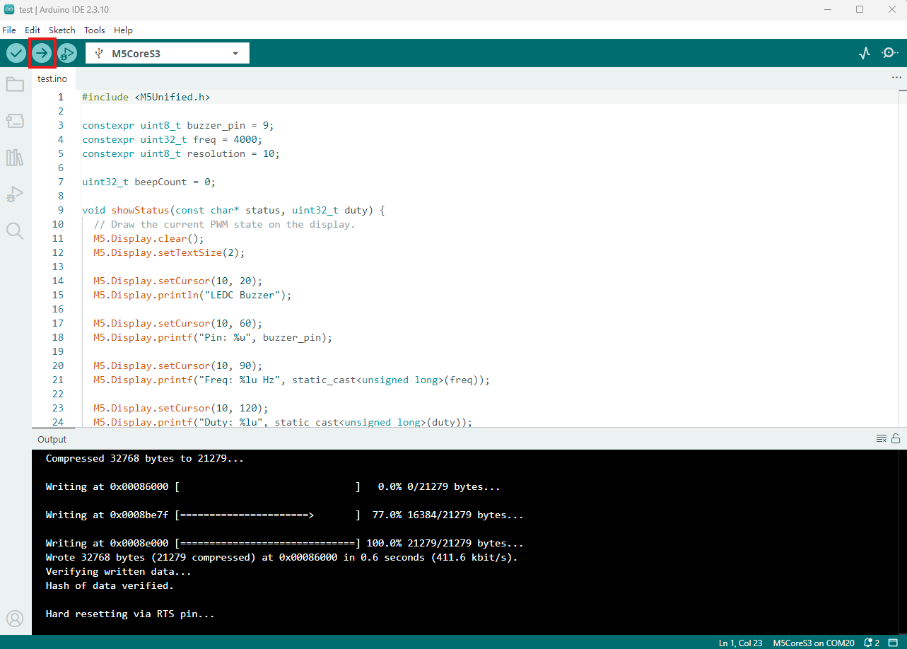
- Copy and paste the example code above into the project code area, select the device port (for details, refer to Compile and Upload), and click the compile and upload button in the upper-left corner of Arduino IDE. Wait for the program to compile and upload to the device.
5. Buzzer PWM Output
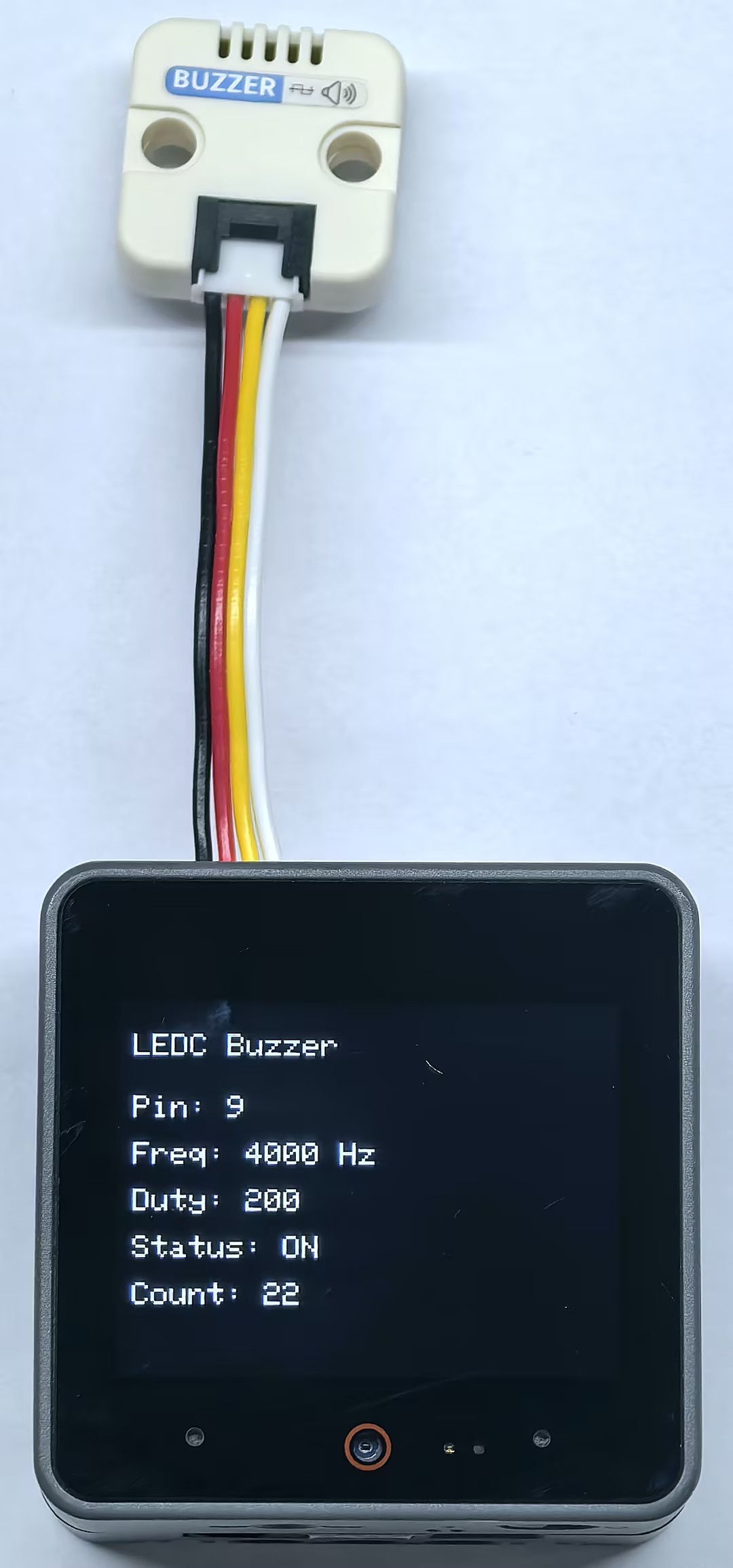
- After startup, the program checks whether the LEDC PWM output is successfully attached to GPIO9. During normal operation, the buzzer outputs 4 kHz PWM with a duty value of 200 for 100 ms, then stops PWM for about 3 seconds. The CoreS3 display shows the pin, frequency, duty value, current status, and beep count.
Page Tools