

Arduino Quick Start
2. Devices & Examples
3. M5Unified
4. M5GFX
5. Extensions
Unit
Module
Atomic
Tab5
IoT
Accessories
Stamp Timer Power Arduino Tutorial
1. Prerequisites
- Environment Setup: Refer to the Arduino IDE Getting Started Guide to install the IDE, then install the board package and driver libraries required for the development board in use.
- Required Driver Library:
- Required Hardware:

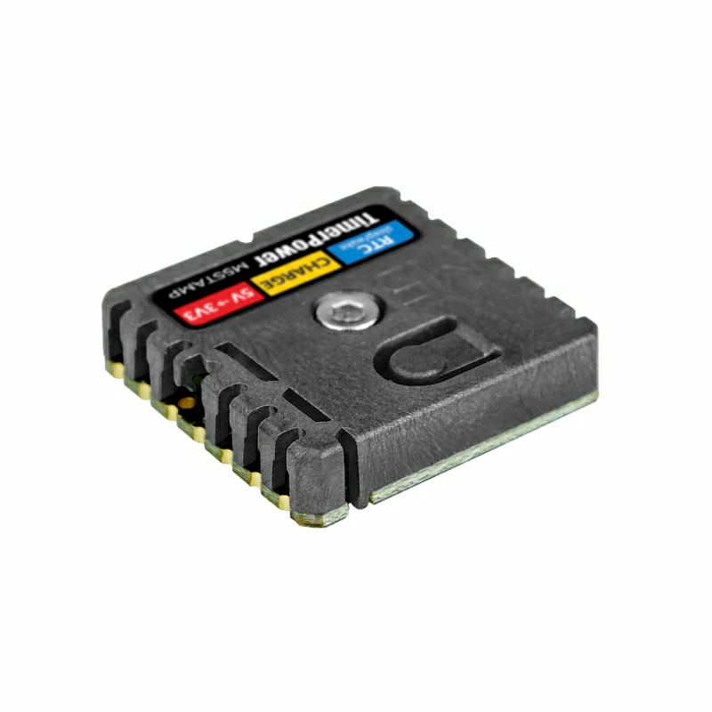
2. Notes
+5VOUT is the output terminal of Stamp Timer Power. Do not directly power it from an external supply by reverse-feeding it.
Stamp Timer Power must be supplied with a stable external 5V power source through 5VIN to operate normally and provide +5VOUT. +5VOUT can supply power to the host through the controller's PORT.A.
HOLD is the 5V output hold-control terminal of Stamp Timer Power. It uses 3.3V logic levels: a high level keeps the +5VOUT output enabled, while a low level disables the +5VOUT output.
+5VOUT, set cfg.output_power = false in the program to prevent the controller from reverse-driving the 5V output of PORT.A.3. Example Program
#include <M5Unified.h>

static constexpr bool SET_RTC_ON_BOOT = true;
static constexpr uint32_t TIMER_SECONDS = 5;
static constexpr uint32_t DISPLAY_INTERVAL_MS = 1000;

static bool startTimer()
{
    const uint32_t actualMs = M5.Rtc.setTimerIRQ(TIMER_SECONDS * 1000UL);
    if (actualMs == 0) {
        return false;
    }

    Serial.printf("RTC timer: %lu seconds\n",
                  static_cast<unsigned long>(actualMs / 1000UL));
    return true;
}

static void stopWithError(const char* message)
{
    Serial.println(message);
    M5.Display.println(message);
    while (true) {
        delay(1000);
    }
}

void setup()
{
    Serial.begin(115200);

    auto cfg = M5.config();
    cfg.output_power = false;
    cfg.internal_rtc = false;
    cfg.external_rtc = false;
    M5.begin(cfg);

    M5.Display.setFont(&fonts::FreeMonoBold9pt7b);
    M5.Display.setCursor(0, 0);
    M5.Display.println("Stamp Timer Power");

    if (!M5.Rtc.begin(&M5.Ex_I2C)) {
        stopWithError("RTC init failed");
    }

    if (SET_RTC_ON_BOOT) {
        const m5::rtc_datetime_t dateTime{
            m5::rtc_date_t(2026, 9, 2, 3),
            m5::rtc_time_t(12, 0, 0),
        };
        M5.Rtc.setDateTime(dateTime);
    }

    M5.Rtc.setSystemTimeFromRtc();

    if (M5.Rtc.getVoltLow()) {
        Serial.println("RTC voltage low flag: SET");
    } else {
        Serial.println("RTC voltage low flag: CLEAR");
    }

    M5.Rtc.disableIRQ();
    if (!startTimer()) {
        stopWithError("RTC timer setup failed");
    }
}

void loop()
{
    M5.update();

    static bool timerFiredSinceLastDisplay = false;
    const bool irq = M5.Rtc.getIRQstatus();
    if (irq) {
        Serial.println("RTC timer fired");
        timerFiredSinceLastDisplay = true;
        M5.Rtc.clearIRQ();
        M5.Rtc.disableIRQ();
        if (!startTimer()) {
            stopWithError("RTC timer restart failed");
        }
    }

    static uint32_t lastDisplayMs = 0;
    if (millis() - lastDisplayMs >= DISPLAY_INTERVAL_MS) {
        lastDisplayMs = millis();
        const bool displayIrq = timerFiredSinceLastDisplay;

        m5::rtc_datetime_t dateTime{};
        const bool readOk = M5.Rtc.getDateTime(&dateTime);

        M5.Display.fillScreen(BLACK);
        M5.Display.setCursor(0, 0);
        M5.Display.println("Stamp Timer Power");

        if (readOk) {
            Serial.printf("RTC: %04d-%02d-%02d %02d:%02d:%02d, IRQ=%s\n",
                          dateTime.date.year, dateTime.date.month,
                          dateTime.date.date, dateTime.time.hours,
                          dateTime.time.minutes, dateTime.time.seconds,
                          displayIrq ? "FIRED" : "WAITING");
            M5.Display.printf("%04d-%02d-%02d\n%02d:%02d:%02d\n",
                              dateTime.date.year, dateTime.date.month,
                              dateTime.date.date, dateTime.time.hours,
                              dateTime.time.minutes, dateTime.time.seconds);
        } else {
            Serial.println("RTC read failed");
            M5.Display.println("RTC read failed");
        }

        M5.Display.printf("IRQ: %s", displayIrq ? "FIRED" : "WAITING");
        timerFiredSinceLastDisplay = false;
    }

    delay(100);
}4. Compile and Upload
- Download mode: Press and hold the CoreS3 reset button for approximately 2 seconds. Release it when the internal green LED lights up. The green LED turns off after release, indicating that the device has entered download mode and is ready for flashing.
.gif)
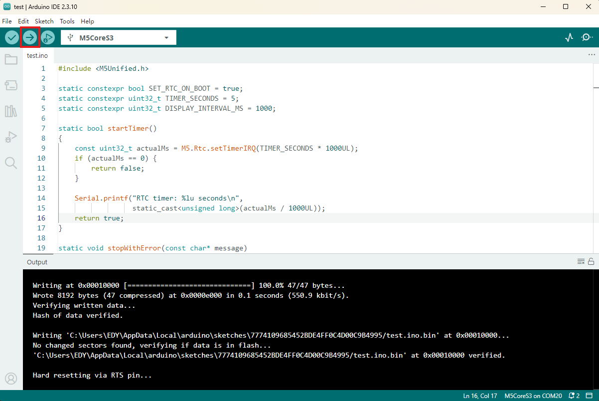
- Select the device port in Arduino IDE, paste the example program above, and click the compile and upload button in the upper-left corner. Wait for the program to finish compiling and uploading to the device.
5. Result
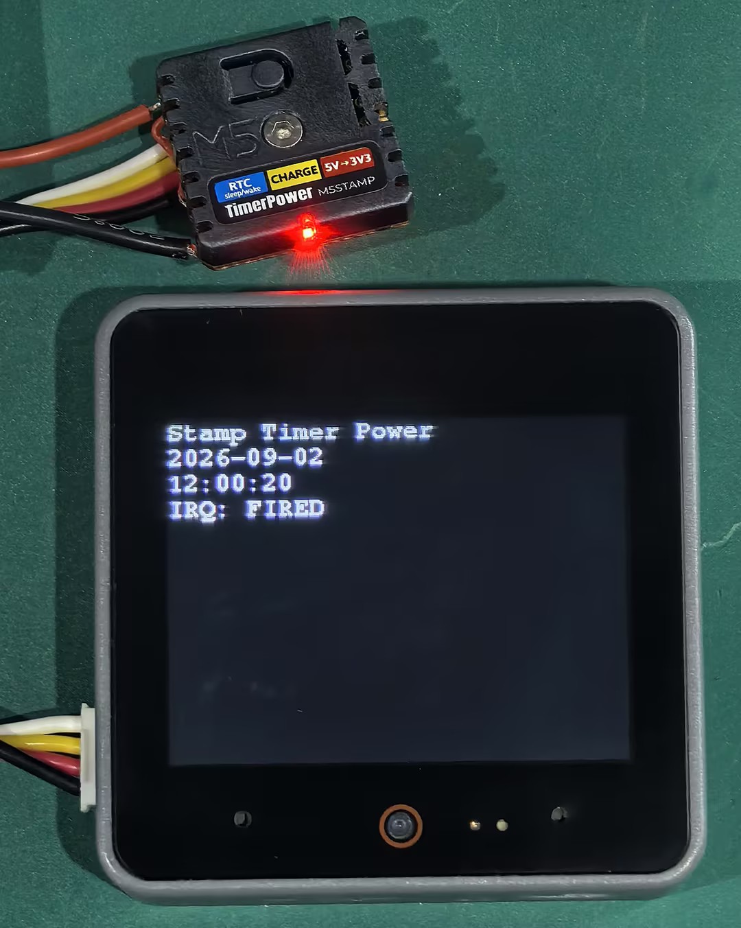
After uploading and running the program, the CoreS3 display shows the current RTC date and time from Stamp Timer Power. The timer triggers an IRQ approximately every 5 seconds. Set the Serial Monitor baud rate to 115200 to see output similar to the following:
Example serial output:
RTC voltage low flag: CLEAR
RTC timer: 5 seconds
RTC: 2026-09-02 12:00:00, IRQ=WAITING
RTC: 2026-09-02 12:00:01, IRQ=WAITING
......
RTC: 2026-09-02 12:00:04, IRQ=WAITING
RTC timer fired
RTC timer: 5 seconds
RTC: 2026-09-02 12:00:05, IRQ=FIRED
......
RTC: 2026-09-02 12:00:09, IRQ=WAITING
RTC timer fired
RTC timer: 5 seconds
RTC: 2026-09-02 12:00:10, IRQ=WAITING