

Arduino Quick Start
2. Devices & Examples
3. M5Unified
4. M5GFX
5. Extensions
Unit
Module
Atomic
Tab5
IoT
Accessories
Unit SSR Arduino Tutorial
1. Preparations
Environment Setup: Refer to the Arduino IDE Getting Started Guide to complete IDE installation, and install the corresponding board manager and required driver libraries for the development board used.
Required Driver Libraries:
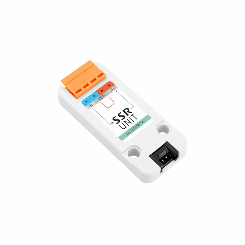
Required Hardware Products:

2. Notes
Pin Compatibility
Since pin configurations vary across different host devices, M5Stack provides a pin compatibility table for reference. Modify the example program according to your actual pin connections.
3. Example Program
Note
Unit SSR is only suitable for single-phase AC 220 ~ 250V loads, with a maximum load current of 2A. Disconnect the power before connecting or adjusting high-voltage AC wiring. Live operation is prohibited.
- This tutorial uses a CoreS3 as the main controller with a Unit SSR. Unit SSR is controlled by a GPIO digital signal, and its corresponding pin after connection is
G9 (DIN).
cpp
1 2 3 4 5 6 7 8 9 10 11 12 13 14 15 16 17 18 19 20
#include <M5Unified.h>

#define DIN_PIN GPIO_NUM_9

void setup() {
  M5.begin();
  M5.Lcd.clear();
  M5.Lcd.setFont(&fonts::FreeMonoBold12pt7b);
  M5.Lcd.setTextColor(YELLOW, BLACK);
  M5.Lcd.setTextDatum(bottom_center);
  M5.Lcd.drawCenterString("Unit SSR Example", 160, 100);
  pinMode(DIN_PIN, OUTPUT);
}

void loop(void) {
  digitalWrite(DIN_PIN, HIGH);
  delay(1000);
  digitalWrite(DIN_PIN, LOW);
  delay(1000);
}4. Compile and Upload
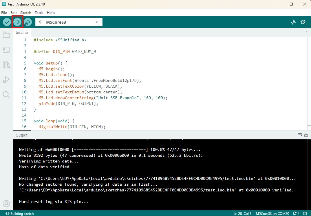
- Copy and paste the example code above into the project code area, select the device port (for details, refer to Compile and Upload), and click the compile and upload button in the upper-left corner of Arduino IDE. Wait for the program to compile and upload to the device.
5. SSR On/Off Control
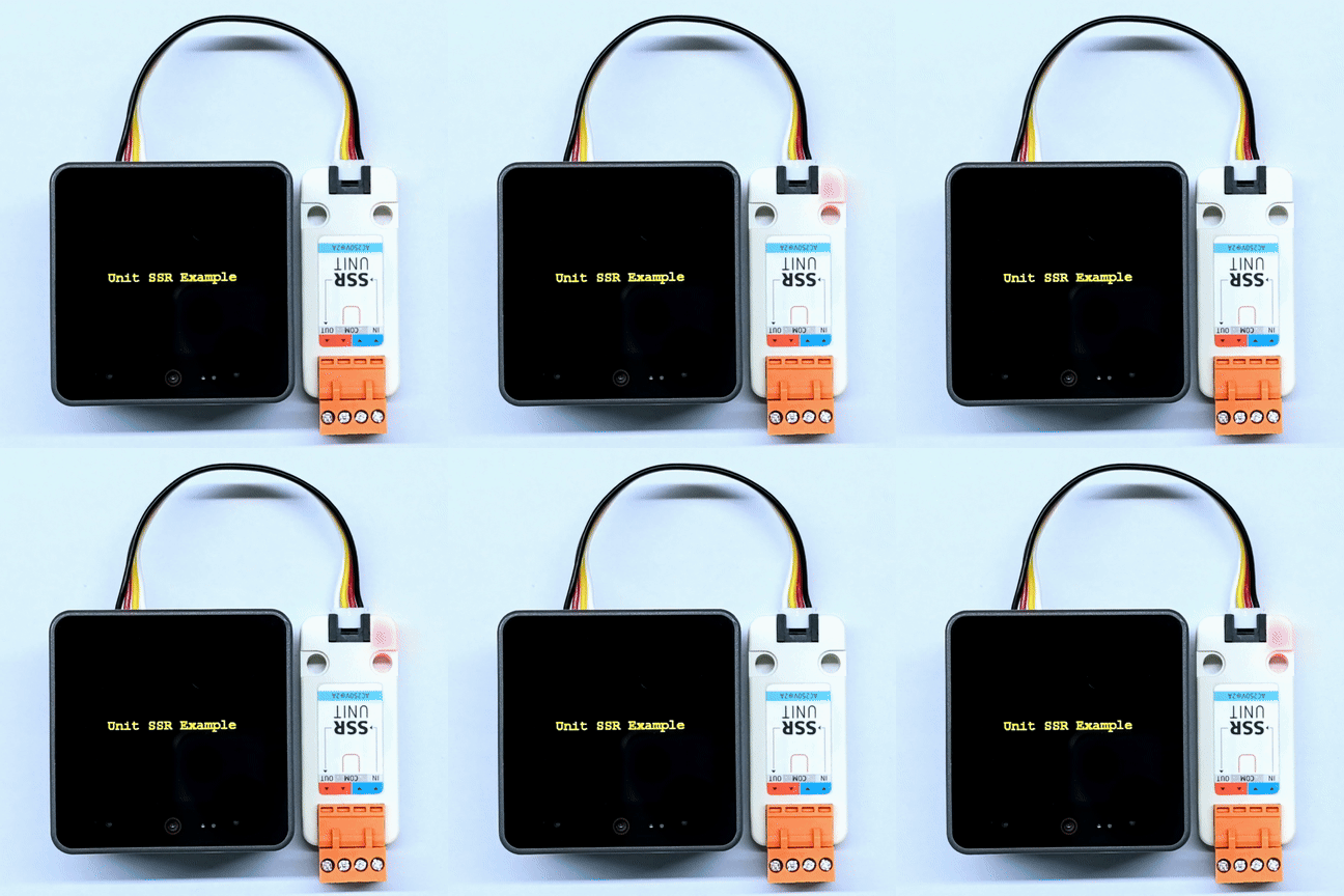
- After the program starts, the CoreS3 display shows
Unit SSR Example.G9switches between high and low levels every 1 second, causing the AC load controlled by Unit SSR to alternate between on and off in a 1-second cycle. The red LED indicates the on/off status.
Page Tools