

Arduino Quick Start
2. Devices & Examples
3. M5Unified
4. M5GFX
5. Extensions
Unit
Module
Atomic
Tab5
IoT
Accessories
Module13.2 4Relay v1.1 Arduino Tutorial
1. Preparation
- Environment Setup: Refer to the Arduino IDE Getting Started Guide to complete IDE installation, and install the corresponding board package and driver based on the actual host used.
- Required Driver Libraries:
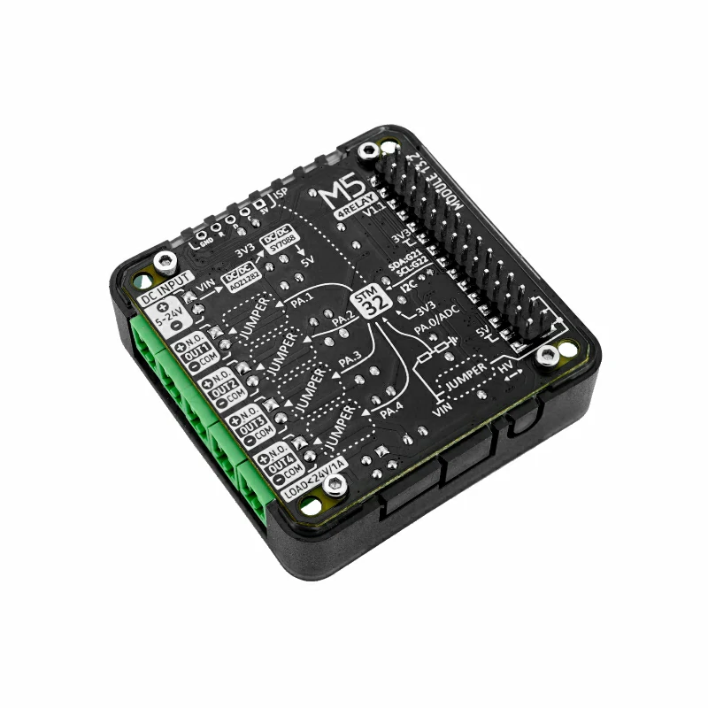
- Hardware Products Used:

2. Precautions
Load and Wiring
Module13.2 4Relay v1.1 only supports DC circuit switching. The specified maximum load capacity for the 4 channels is 24W (DC 24V@1A). The relay terminals are
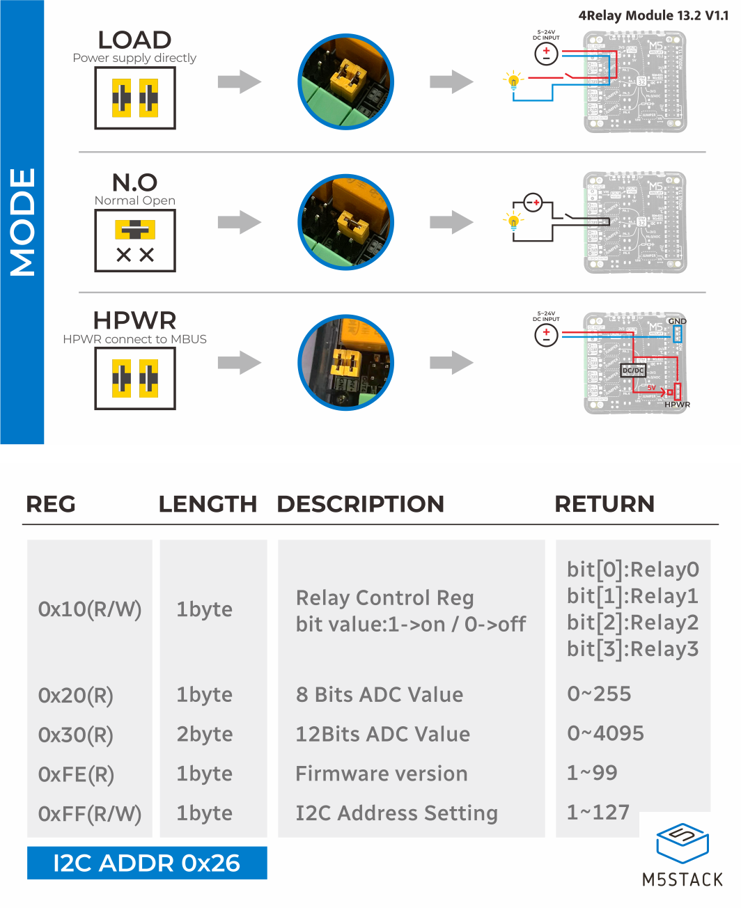
COM and NO. Connect the wiring according to the actual load and power supply specifications. Disconnect the power supply before wiring, disconnecting wires, or replacing the load.Operating Mode
Install the jumper caps according to the product wiring instructions to select active or passive mode. When using an external DC 5 ~ 24V power supply, confirm that the power polarity and load voltage meet the product specifications. Do not connect AC power to this module.
Pin Compatibility
Since the I2C pin configurations vary between host devices, refer to the Pin Compatibility Table in the product documentation before use, and modify the example program according to the actual connections.
3. Example Program
This tutorial uses CoreS3 with Module13.2 4Relay v1.1. The module communicates via I2C and uses the default address 0x26. The I2C pins connected to CoreS3 are G12 (SDA) and G11 (SCL). The CoreS3 touchscreen controls the relays: tap STEP to switch the current channel, tap ALL ON to turn on all channels, and tap ALL OFF to turn off all channels.
cpp
1 2 3 4 5 6 7 8 9 10 11 12 13 14 15 16 17 18 19 20 21 22 23 24 25 26 27 28 29 30 31 32 33 34 35 36 37 38 39 40 41 42 43 44 45 46 47 48 49 50 51 52 53 54 55 56 57 58 59 60 61 62 63 64 65 66 67 68 69 70 71 72 73 74 75 76 77 78 79 80 81 82 83 84 85 86 87 88 89 90 91 92 93 94 95 96 97 98 99 100 101 102 103 104 105 106 107 108 109 110 111 112 113 114 115 116 117 118 119 120 121 122 123 124 125 126 127
#include <M5Unified.h>
#include "Module_4RELAY.h"

MODULE_4RELAY relay;
TwoWire *relayWire = &Wire1;

uint8_t currentChannel = 0;

constexpr uint8_t RELAY_SDA = 12;
constexpr uint8_t RELAY_SCL = 11;
constexpr int16_t TOUCH_BUTTON_Y = 176;
constexpr int16_t TOUCH_BUTTON_HEIGHT = 58;
constexpr int16_t TOUCH_BUTTON_WIDTH = 100;
constexpr int16_t TOUCH_BUTTON_GAP = 6;

int16_t getButtonX(uint8_t index)
{
    return TOUCH_BUTTON_GAP + index * (TOUCH_BUTTON_WIDTH + TOUCH_BUTTON_GAP);
}

int8_t getTouchedButton(int16_t x, int16_t y)
{
    if (y < TOUCH_BUTTON_Y || y >= TOUCH_BUTTON_Y + TOUCH_BUTTON_HEIGHT) {
        return -1;
    }

    for (uint8_t index = 0; index < 3; ++index) {
        const int16_t buttonX = getButtonX(index);
        if (x >= buttonX && x < buttonX + TOUCH_BUTTON_WIDTH) {
            return index;
        }
    }
    return -1;
}

void drawTouchButton(uint8_t index, const char *label)
{
    const int16_t x = getButtonX(index);
    M5.Display.fillRoundRect(x, TOUCH_BUTTON_Y, TOUCH_BUTTON_WIDTH,
                             TOUCH_BUTTON_HEIGHT, 5, TFT_DARKGREY);
    M5.Display.drawRoundRect(x, TOUCH_BUTTON_Y, TOUCH_BUTTON_WIDTH,
                             TOUCH_BUTTON_HEIGHT, 5, TFT_ORANGE);
    M5.Display.setTextDatum(MC_DATUM);
    M5.Display.setTextColor(TFT_WHITE, TFT_DARKGREY);
    M5.Display.drawString(label, x + TOUCH_BUTTON_WIDTH / 2,
                          TOUCH_BUTTON_Y + TOUCH_BUTTON_HEIGHT / 2);
}

void showStatus(const char *action)
{
    const uint8_t state = relay.getAllRelayState();

    M5.Display.fillScreen(TFT_BLACK);
    M5.Display.setTextColor(TFT_WHITE, TFT_BLACK);
    M5.Display.setTextSize(2);
    M5.Display.setTextDatum(TL_DATUM);
    M5.Display.drawString("Module13.2 4Relay", 8, 8);
    M5.Display.drawString(action, 8, 32);

    for (uint8_t index = 0; index < 4; ++index) {
        const bool isOn = (state >> index) & 0x01;
        M5.Display.setCursor(8, 60 + index * 26);
        M5.Display.printf("CH%u: %s%s", index + 1, isOn ? "ON" : "OFF",
                          index == currentChannel ? "  <" : "");
    }

    Serial.printf("%s | relay state: 0x%02X\n", action, state);
    drawTouchButton(0, "STEP");
    drawTouchButton(1, "ALL ON");
    drawTouchButton(2, "ALL OFF");
}

void setup()
{
    M5.begin();
    Serial.begin(115200);

    while (!relay.begin(relayWire, MODULE_4RELAY_ADDR, RELAY_SDA, RELAY_SCL,
                        200000L)) {
        Serial.println("4RELAY INIT ERROR");
        M5.Display.fillScreen(TFT_BLACK);
        M5.Display.setTextColor(TFT_RED, TFT_BLACK);
        M5.Display.setTextSize(2);
        M5.Display.setTextDatum(TL_DATUM);
        M5.Display.drawString("4RELAY INIT ERROR", 8, 8);
        delay(1000);
    }

    Serial.println("4RELAY INIT SUCCESS");
    relay.setAllRelay(false);
    showStatus("Ready");
}

void loop()
{
    M5.update();

    const auto touch = M5.Touch.getDetail();
    if (touch.wasClicked()) {
        switch (getTouchedButton(touch.x, touch.y)) {
        case 0: {
            const bool nextState = !relay.getRelayState(currentChannel);
            const bool success = relay.setRelay(currentChannel, nextState);
            currentChannel = (currentChannel + 1) % 4;
            showStatus(success ? "Channel updated" : "Channel update error");
            break;
        }

        case 1: {
            const bool success = relay.setAllRelay(true);
            showStatus(success ? "All ON" : "All ON error");
            break;
        }

        case 2: {
            const bool success = relay.setAllRelay(false);
            showStatus(success ? "All OFF" : "All OFF error");
            break;
        }

        default:
            break;
        }
    }

    delay(20);
}4. Compile and Upload
- 1. Enter download mode: Press and hold the reset button on CoreS3 for about 2 seconds until the internal green LED lights up, then release it. The device will enter download mode and wait for the program to be written.
Note
Before burning a program, different devices need to enter download mode, and the procedure may vary depending on the host device. For details, refer to the device program download tutorial list at the bottom of the Arduino IDE Getting Started Guide page.
.gif)
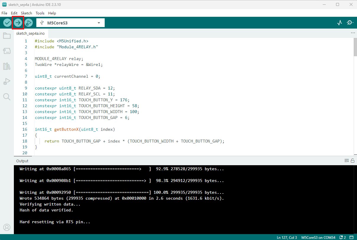
- 2. Select the device port and click the compile and upload button in the upper-left corner of Arduino IDE. Wait for the program to finish compiling and uploading to the device.
5. Relay Control
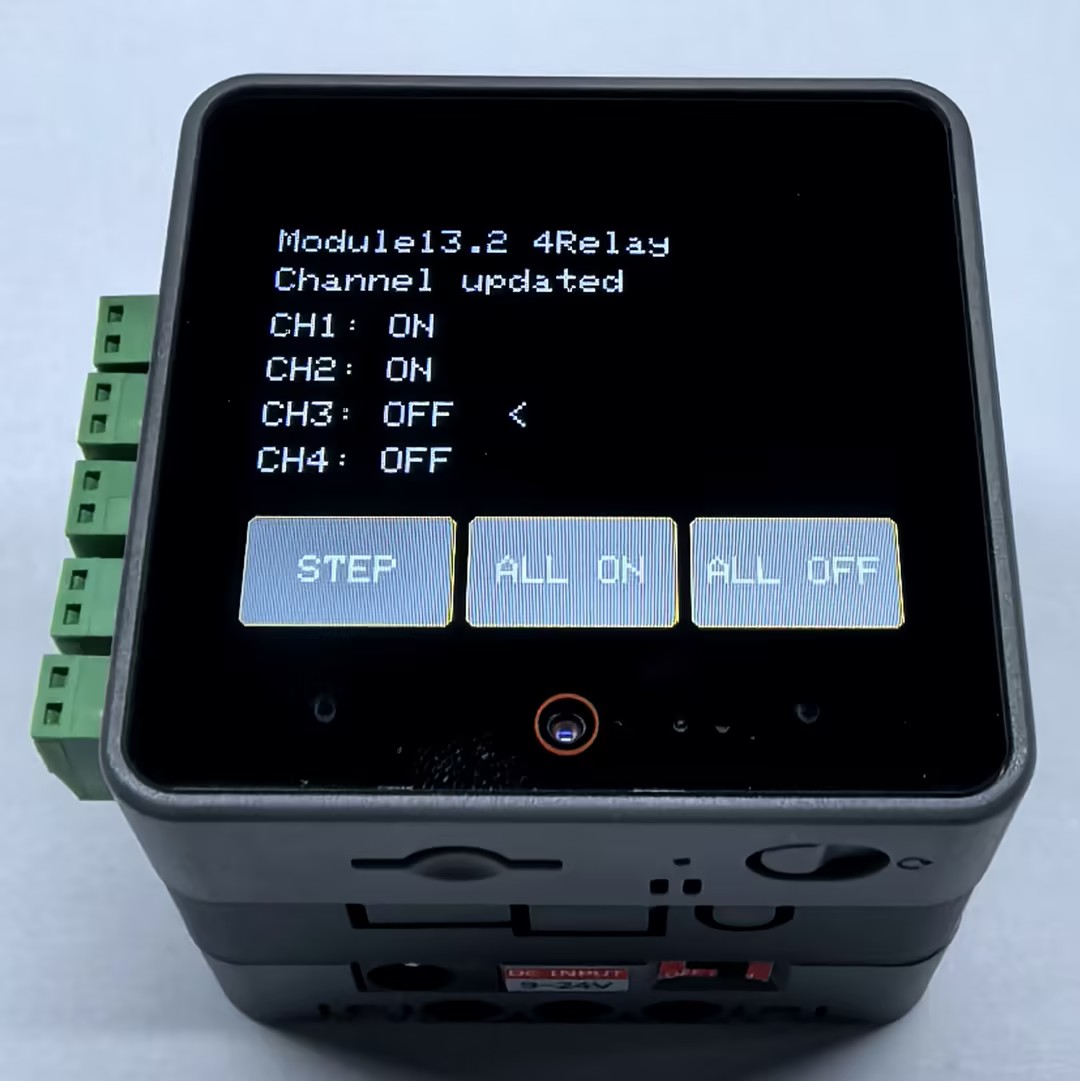
After the program starts, the CoreS3 screen displays the status of the 4 relays. The < symbol indicates the channel selected for the next toggle.
- Tap
STEP: Toggle the current channel, then select the next channel automatically. - Tap
ALL ON: Turn on all 4 relays. - Tap
ALL OFF: Turn off all 4 relays.
Use a multimeter or a low-voltage DC load that meets the specifications to verify the continuity between the COM and NO terminals before connecting the actual load.
Page Tools