

Arduino 上手教程
2. 设备开发 & 案例程序
3. M5Unified
4. M5GFX
5. 扩展模块
Unit
Module
Atomic
Tab5
IoT
PaperMono M5PM1 & M5IOE1 电源管理
1. 多级电源开关设计
PaperMono 内部集成 M5PM1 + M5IOE1,结合硬件电路实现了多级电源开关,不同的级别的电源开关对应控制了相关的外设与接口供电。用户可根据运行需求,切换不同级别的电源使能,关闭未使用的外设部分,实现整机低功耗。
M5PM1 / M5IOE1 驱动库
使用 M5PM1 / M5IOE1 驱动库能够非常便捷地配置 M5PM1 / M5IOE1 的引脚功能,用于低功耗唤醒以及外设供电开关。
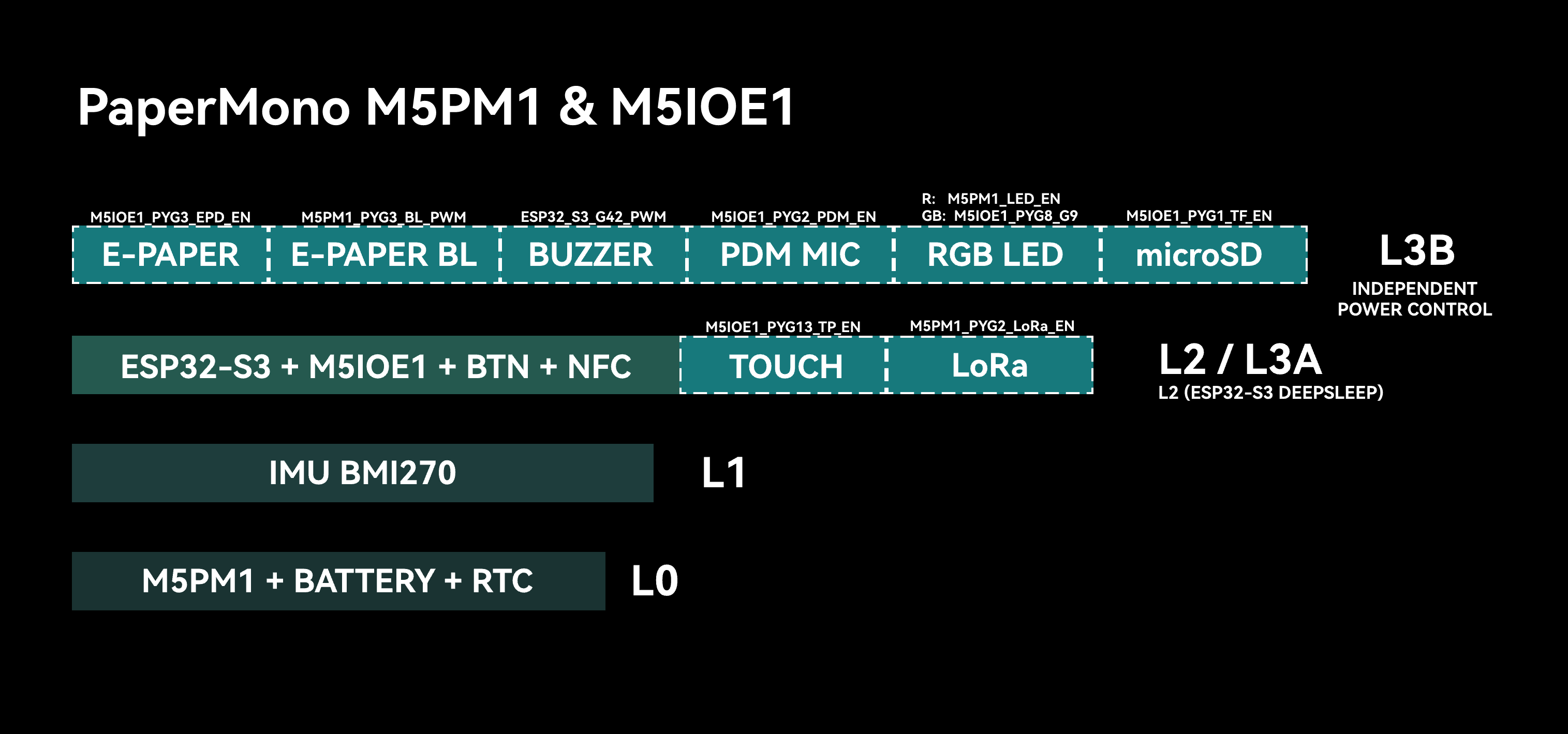
L0
此级电源条件下,电池保持对 M5PM1 以及 RTC 的供电。电池电量未耗尽的情况下,该层电源将一直保持,M5PM1 支持基础的按键开关机操作及 RTC 中断唤醒。
L1
此级电源条件下,将新启用 IMU 外设供电。该层级的电源开关使用 M5PM1 的 3V3_L1_EN,可通过以下 API 实现开关控制。
pm1.setLdoEnable(true); // L1 ON
pm1.setLdoEnable(false); // L1 OFF同时,IMU 的 INT1 中断引脚连接至 M5PM1 的 PYG4,可通过配置相关的寄存器实现保持 IMU 供电,M5PM1 进入休眠状态,通过翻转设备,触发 IMU 中断(高电平有效)唤醒 M5PM1。可通过以下 API 实现 IMU (L1) 供电保持。
pm1.setLdoEnable(true);
pm1.ldoSetPowerHold(true);
pm1.setLedEnLevel(true);
pm1.shutdown();L2 \ L3A
此级电源条件下,将新启用 ESP32-S3、LoRa 模块、NFC/RFID 模块、M5IOE1 拓展芯片、用户按键上拉、屏幕触摸中断、蜂鸣器供电以及 RGB LED 红色灯珠控制。该层级的电源开关使用 M5PM1 的 3V3_L2_EN,可通过以下 API 实现开关控制。
pm1.setDcdcEnable(true); // L2 ON
pm1.setDcdcEnable(false); // L2 OFF当 ESP32-S3 处于休眠状态时,电源处于 L2 级。当 ESP32-S3 处于工作状态时,电源处于 L3A 级。 ESP32-S3 可通过控制 M5PM1 进入休眠,关断自身的供电 (L2 -> L1/L0)。
L3B
L3B 层级控制屏幕、触控、microSD检测、PDM、RGB 等功耗较高的外设的供电或相关配置。该层级基于 M5IOE1 IO 拓展芯片实现控制,允许独立控制该层级的一些外设。
| M5IOE1 | PYG1 | PYG2 | PYG3 | PYG4_ADC2 | PYG5 | PYG6 | PYG8 | PYG9 | PYG10 | PYG12 | PYG13 | PYG14 |
|---|---|---|---|---|---|---|---|---|---|---|---|---|
| microSD | PYB_TF_DET | PYB_TF_EN | ||||||||||
| LoRa | PYB_LoRa_ANT_SW | PYB_LoRa_RST | ||||||||||
| E-Paper | PYB_EPD_EN | PYB_EINK_RST | ||||||||||
| NFC / RFID | PYB_NFC_EN | |||||||||||
| Touch | PYB_TP_RST | PYB_TP_EN | ||||||||||
| RGB LED | PYB_LED_G | PYB_LED_B | ||||||||||
| PDM | PYB_PDM_EN |
- PYB_TF_DET: microSD 检测
- PYB_TF_EN: microSD 供电
- PYB_LoRa_ANT_SW: LoRa 天线开关
- PYB_LoRa_RST: LoRa 复位
- PYB_EPD_EN: E-Paper 供电
- PYB_EINK_RST: E-Paper 复位
- PYB_NFC_EN: NFC / RFID 使能与复位
- PYB_LED_G: RGB LED 绿色控制
- PYB_LED_B: RGB LED 蓝色控制
- PYB_PDM_EN: PDM 供电
- PYB_TP_EN: 触控供电
- PYB_TP_RST: 触控复位
2. M5PM1 休眠
手动休眠
M5PM1 可通过程序手动控制进入休眠状态,来降低整机功耗。默认状态下,直接设置休眠将回退至 L0 级电源,此时仅 M5PM1 保持供电。
pm1.shutdown();在一些特殊的使用场景 (例如 IMU 唤醒,或是 ESP32-S3 SoC 休眠),允许 M5PM1 进入休眠降低的同时,保持一些层级的外设供电,用于唤醒源或是状态保持。
该类应用需要在 M5PM1 进入休眠模式前,配置对应层级的电源开关引脚状态,并激活状态保持。
I2C 空闲休眠
M5PM1 支持配置 I2C 空闲通信自动休眠状态,来降低整机功耗。进入休眠状态后,ESP32-S3 与 M5PM1 的首次通信将用于 M5PM1 唤醒,因此将通信失败,有效的通信将在唤醒后的下一次通信中完成。
m5pm1_err_t setI2cSleepTime(uint8_t seconds);3. M5PM1 Timer 定时器
M5PM1 支持配置定时器功能,当计时结束后,执行相应的操作,如开机,关机,复位等。
m5pm1_err_t timerSet(uint32_t seconds, m5pm1_tim_action_t action);typedef enum {
M5PM1_TIM_ACTION_STOP = 0b000, // 停止,无动作
// Stop, no action
M5PM1_TIM_ACTION_FLAG = 0b001, // 仅设置标志
// Set flag only
M5PM1_TIM_ACTION_REBOOT = 0b010, // 系统复位
// System reboot
M5PM1_TIM_ACTION_POWERON = 0b011, // 开机
// Power on
M5PM1_TIM_ACTION_POWEROFF = 0b100 // 关机
// Power off
} m5pm1_tim_action_t;定时开机 / 关机案例
案例说明:设备开机后,单击按键 A 配置 10s 定时器触发重新开机,单击按键 B 配置 10s 后定时器触发 M5PM1 关机 (可通过单击电源按键重新开机)。
#include <M5Unified.h>
#include <M5PM1.h>
M5PM1 pm1;
void setup()
{
auto cfg = M5.config();
cfg.clear_display = false;
M5.begin(cfg);
Serial.begin(115200);
const m5pm1_err_t err = pm1.begin(&M5.In_I2C, M5PM1_DEFAULT_ADDR, M5PM1_I2C_FREQ_100K);
if (err != M5PM1_OK) {
Serial.printf("M5PM1 init failed: %d\n", err);
while (true) {
delay(1000);
}
}
M5.Display.setEpdMode(epd_mode_t::epd_fast);
M5.Display.setTextDatum(middle_center);
M5.Display.setFont(&fonts::FreeSansBold18pt7b);
M5.Display.drawString("BtnA: power on after 10s", M5.Display.width() / 2, 280);
M5.Display.drawString("BtnB: power off after 10s", M5.Display.width() / 2, 340);
}
void loop(void)
{
M5.update();
if (M5.BtnA.wasPressed()) {
M5.Display.clear();
M5.Display.setCursor(40, 80);
M5.Display.println("Shutdown");
M5.Display.println(" After 10s");
M5.Display.println(" Power ON");
delay(500);
pm1.timerSet(10, M5PM1_TIM_ACTION_POWERON);
pm1.shutdown();
}
if (M5.BtnB.wasPressed()) {
M5.Display.clear();
M5.Display.setCursor(40, 80);
M5.Display.println(" After 10s");
M5.Display.println(" Power OFF");
delay(500);
pm1.timerSet(10, M5PM1_TIM_ACTION_POWEROFF);
}
}4. IMU 唤醒
BMI270 驱动库
IMU M5PM1 唤醒
电源切换至 L1 Mode, 整机仅 IMU、RTC 和 M5PM1 处于供电状态。在配置 IMU 唤醒功能后,M5PM1 也进入休眠状态,同时保持 L1 的输出供电 (3V3_L1_EN),用于维持 IMU 工作。
此时可通过翻转或移动设备,触发 IMU 唤醒信号,唤醒 M5PM1 重新启动。
M5PM1 唤醒后将重新运行 L0、L1 和 L2 上电流程。ESP32-S3 重新执行初始化。
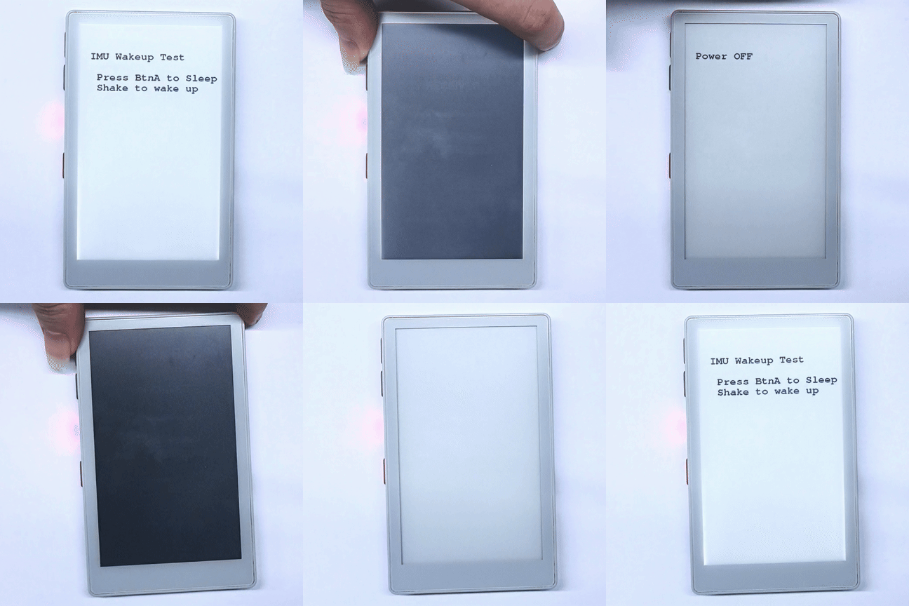
案例说明:设备开机后,单击按键 A 配置 IMU 中断模式与 M5PM1 L1 电源保持,M5PM1 进入休眠。此时翻转或移动设备即可触发 M5PM1 唤醒,ESP32-S3 重新上电。
#include <M5Unified.h>
#include <M5PM1.h>
#include <Wire.h>
#include "SparkFun_BMI270_Arduino_Library.h"
BMI270 imu;
M5PM1 pm1;
void setup(void)
{
auto cfg = M5.config();
cfg.clear_display = false;
M5.begin(cfg);
Serial.begin(115200);
Wire1.setPins(M5.getPin(m5::pin_name_t::in_i2c_sda), M5.getPin(m5::pin_name_t::in_i2c_scl));
// Initialize PM1
m5pm1_err_t err = pm1.begin(&M5.In_I2C, M5PM1_DEFAULT_ADDR, M5PM1_I2C_FREQ_100K);
if (err == M5PM1_OK) {
Serial.println("PM1 initialization successful");
pm1.gpioSetWakeEnable(M5PM1_GPIO_NUM_4, true);
pm1.gpioSetWakeEdge(M5PM1_GPIO_NUM_4, M5PM1_GPIO_WAKE_FALLING); // Falling edge
} else {
Serial.printf("PM1 initialization failed, error code: %d\n", err);
}
pm1.setSingleResetDisable(false);
// Check if sensor is connected and initialize
while(imu.beginI2C(BMI2_I2C_PRIM_ADDR, Wire1) != BMI2_OK)
{
Serial.println("Error: BMI270 not connected, check wiring and I2C address!");
delay(1000);
}
imu.disableFeature(BMI2_ANY_MOTION);
Serial.println("BMI270 initialization successful");
M5.Display.setEpdMode(epd_mode_t::epd_fast);
M5.Display.setFont(&fonts::FreeMonoBold18pt7b);
M5.Display.clear();
M5.Display.setCursor(40, 100);
M5.Display.printf("IMU Wakeup Test\n\n");
M5.Display.println(" Press BtnA to Sleep");
M5.Display.println(" Shake to wake up");
}
void loop(void)
{
M5.update();
if (M5.BtnA.wasPressed()) {
int8_t ret = imu.enableFeature(BMI2_ANY_MOTION);
// Optional
// bmi2_sens_config config;
// config.type = BMI2_ANY_MOTION;
// config.cfg.any_motion.threshold = 0xA0;// 1LSB equals to 0.48mg. Default is 83mg. Lower is more sensitive
// config.cfg.any_motion.duration = 0x0A; // 1LSB equals 20ms. Default is 100ms.
// ret |= imu.setConfig(config);
//
bmi2_int_pin_config intPinConfig;
intPinConfig.pin_type = BMI2_INT1;
intPinConfig.int_latch = BMI2_INT_NON_LATCH;
intPinConfig.pin_cfg[0].lvl = BMI2_INT_ACTIVE_LOW;
intPinConfig.pin_cfg[0].od = BMI2_INT_PUSH_PULL;
intPinConfig.pin_cfg[0].output_en = BMI2_INT_OUTPUT_ENABLE;
intPinConfig.pin_cfg[0].input_en = BMI2_INT_INPUT_DISABLE;
ret |= imu.setInterruptPinConfig(intPinConfig);
ret |= imu.mapInterruptToPin(BMI2_ANY_MOTION_INT, BMI2_INT1);
if (!ret){
Serial.println("BMI270 AnyMotionInterrupt enabled successfully");
} else {
Serial.println("Failed to enable BMI270 AnyMotionInterrupt");
}
M5.Display.clear();
M5.Display.setCursor(40, 100);
M5.Display.println("Power OFF");
delay(1000);
// Shutdown
pm1.setLdoEnable(true);
pm1.ldoSetPowerHold(true);
pm1.setLedEnLevel(true);
pm1.shutdown();
}
} 按下按键 A 后,程序会启用 BMI270 任意运动检测,将中断映射到低电平有效的 INT1,并保持 M5PM1 的 L1 供电后关闭整机。翻转或移动设备触发中断时,M5PM1 会恢复各级供电,ESP32-S3 重新上电并从 setup() 开始运行。
IMU 唤醒 ESP32-S3
M5PM1 的 PYG1_IRQ 引脚在电路上连接到了 ESP32-S3 的 G1 上,可以通过链式的唤醒信号实现 ESP32-S3 唤醒,实现步骤如下:
- 配置 M5PM1 PYG4 为输入模式,该引脚连接 IMU 的 INT1 输出信号。
- 配置 M5PM1 PYG4_IRQ 为 IRQ 输入信号引脚。当 PYG4 (IMU 产生中断信号) 引脚状态变化时, PYG1_IRQ 引脚将输出中断信号
- 配置 ESP32-S3 进入休眠,配置唤醒引脚为 G1
- 翻转或移动设备:触发 IMU 唤醒信号 -> 触发 M5PM1 PYG1_IRQ -> 唤醒 ESP32-S3
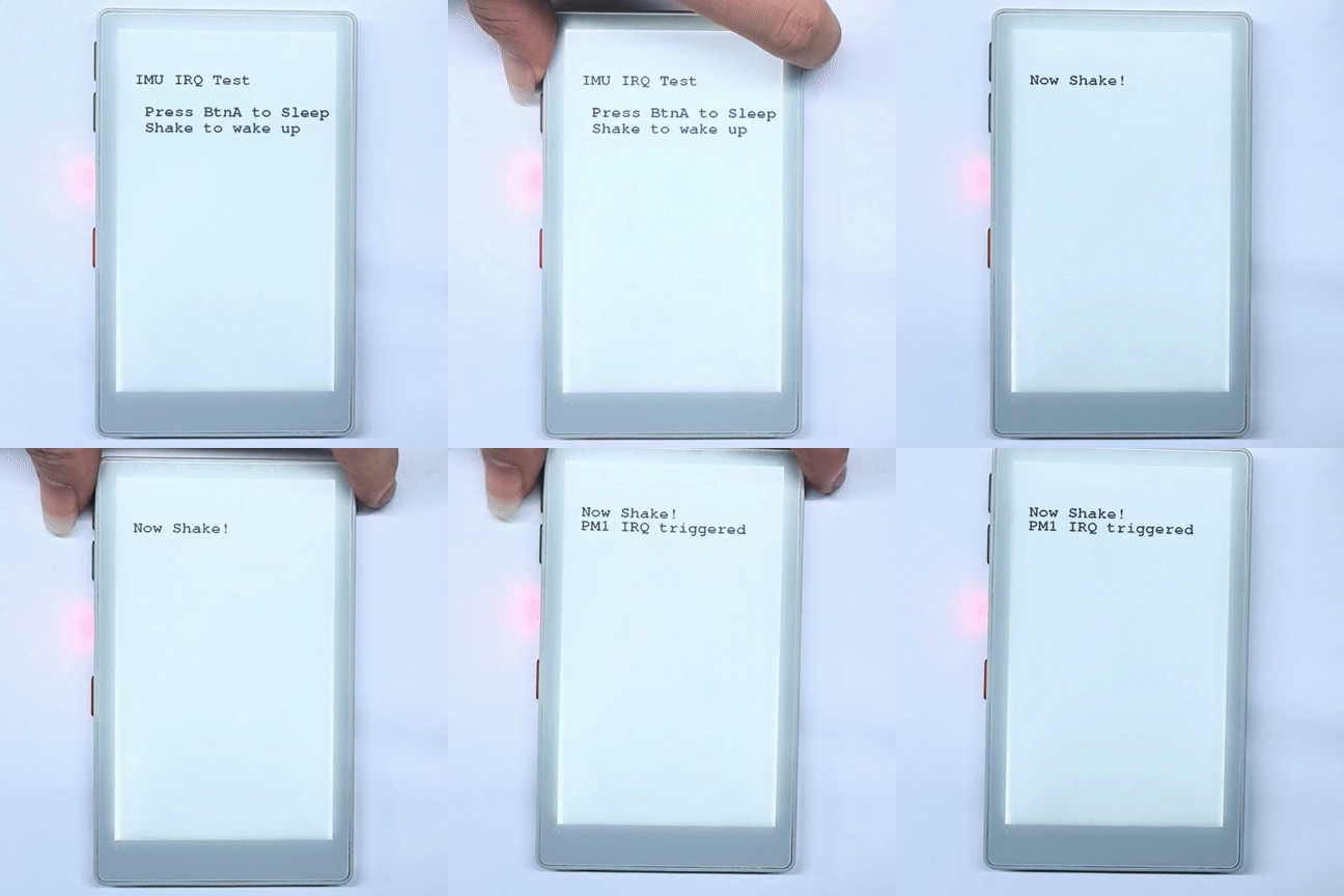
案例说明:设备开机后,单击按键 A 配置 IMU 中断模式。翻转或移动设备即可触发 GPIO 中断处理函数。再次单击按键 A 可清除 M5PM1 IRQ 标志位,再次进行测试。
#include <M5Unified.h>
#include <M5PM1.h>
#include <Wire.h>
#include "SparkFun_BMI270_Arduino_Library.h"
#include "driver/rtc_io.h"

BMI270 imu;
M5PM1 pm1;

void setup(void)
{
    auto cfg = M5.config();
    cfg.clear_display = false;
    M5.begin(cfg);
    Serial.begin(115200);

    Wire1.setPins(M5.getPin(m5::pin_name_t::in_i2c_sda), M5.getPin(m5::pin_name_t::in_i2c_scl));

    // Initialize PM1
    m5pm1_err_t err = pm1.begin(&M5.In_I2C, M5PM1_DEFAULT_ADDR, M5PM1_I2C_FREQ_100K);

    if (err == M5PM1_OK) {
        Serial.println("PM1 initialization successful");
        pm1.irqClearGpioAll();
        pm1.irqClearSysAll();
        pm1.irqClearBtnAll();

        pm1.irqSetGpioMaskAll(M5PM1_IRQ_MASK_ENABLE);
        pm1.irqSetSysMaskAll(M5PM1_IRQ_MASK_ENABLE);
        pm1.irqSetBtnMaskAll(M5PM1_IRQ_MASK_ENABLE);

        pm1.irqSetGpioMask(M5PM1_IRQ_GPIO4, M5PM1_IRQ_MASK_DISABLE);
        pm1.gpioSetMode(M5PM1_GPIO_NUM_4, M5PM1_GPIO_MODE_INPUT);
        pm1.gpioSetPull(M5PM1_GPIO_NUM_4, M5PM1_GPIO_PULL_UP);

        pm1.gpioSetMode(M5PM1_GPIO_NUM_1, M5PM1_GPIO_MODE_OUTPUT);
        pm1.gpioSetDrive(M5PM1_GPIO_NUM_1, M5PM1_GPIO_DRIVE_PUSHPULL);
        pm1.gpioSetFunc(M5PM1_GPIO_NUM_1, M5PM1_GPIO_FUNC_IRQ);
    } else {
        Serial.printf("PM1 initialization failed, error code: %d\n", err);
    }
    pm1.setSingleResetDisable(false);

    // Check if sensor is connected and initialize
    while(imu.beginI2C(BMI2_I2C_PRIM_ADDR, Wire1) != BMI2_OK)
    {
        Serial.println("Error: BMI270 not connected, check wiring and I2C address!");
        delay(1000);
    }
    imu.disableFeature(BMI2_ANY_MOTION);
    Serial.println("BMI270 initialization successful");

    M5.Display.setEpdMode(epd_mode_t::epd_fast);
    M5.Display.setFont(&fonts::FreeMonoBold18pt7b);
    M5.Display.clear();
    M5.Display.setCursor(40, 100);
    M5.Display.printf("IMU IRQ Test\n\n");
    M5.Display.println("   Press BtnA to Sleep");
    M5.Display.println("   Shake to wake up");
}

volatile bool pm1IrqTriggered = false;

void ARDUINO_ISR_ATTR pm1_irq_handler()
{
    pm1IrqTriggered = true;
}

void loop(void)
{
    M5.update();

    if (pm1IrqTriggered) {
        pm1IrqTriggered = false;

        Serial.println("PM1 IRQ triggered");

        uint16_t status = 0;
        imu.getInterruptStatus(&status);
        Serial.printf("BMI270 interrupt status: 0x%04X\n", status);

        M5.Display.setCursor(40, 130);
        M5.Display.println("PM1 IRQ triggered");
    }

    if (M5.BtnA.wasPressed()) {
        pm1.irqClearGpioAll();
        pm1.irqClearSysAll();
        pm1.irqClearBtnAll();
        int8_t ret = imu.enableFeature(BMI2_ANY_MOTION);
        // Optional
        // bmi2_sens_config config;
        // config.type = BMI2_ANY_MOTION;
        // ret |= imu.getConfig(&config);
        // config.cfg.any_motion.threshold = 0xE0;// 1LSB equals to 0.48mg. Default is 83mg. Lower is more sensitive
        // config.cfg.any_motion.duration = 0x0A; // 1LSB equals 20ms. Default is 100ms.
        // ret |= imu.setConfig(config);

        bmi2_int_pin_config intPinConfig;
        intPinConfig.pin_type = BMI2_INT1;
        intPinConfig.int_latch = BMI2_INT_NON_LATCH;
        intPinConfig.pin_cfg[0].lvl = BMI2_INT_ACTIVE_LOW;// active - low
        intPinConfig.pin_cfg[0].od = BMI2_INT_PUSH_PULL;
        intPinConfig.pin_cfg[0].output_en = BMI2_INT_OUTPUT_ENABLE;
        intPinConfig.pin_cfg[0].input_en = BMI2_INT_INPUT_DISABLE;
        ret |= imu.setInterruptPinConfig(intPinConfig);
        ret |= imu.mapInterruptToPin(BMI2_ANY_MOTION_INT, BMI2_INT1);
        if (!ret){
            Serial.println("BMI270 AnyMotionInterrupt enabled successfully");
        } else {
            Serial.println("Failed to enable BMI270 AnyMotionInterrupt");
        }

        M5.Display.clear();
        M5.Display.setCursor(40, 100);
        M5.Display.println("Now Shake!");

        // Choose either of the two pieces of code below.
        pinMode(GPIO_NUM_1, INPUT_PULLUP);
        attachInterrupt(GPIO_NUM_1, pm1_irq_handler, FALLING);

        // esp_sleep_enable_ext0_wakeup(GPIO_NUM_1, 0);  // 0 = Low
        // rtc_gpio_pullup_en(GPIO_NUM_1);
        // Serial.println("Going to sleep now");
        // esp_deep_sleep_start();
    }
} 程序将 BMI270 INT1 经 M5PM1 GPIO4 转换为 PYG1_IRQ,并连接到 ESP32-S3 G1。当前代码默认在 G1 上注册下降沿中断,检测到运动后在屏幕和串口监视器中显示中断状态;若要实际测试深度休眠唤醒,需要改用代码中已注释的 esp_sleep_enable_ext0_wakeup() 和 esp_deep_sleep_start()。
5. RTC 唤醒
RTC M5PM1 唤醒
电源切换至 L1 Mode, 整机仅 IMU、RTC 和 M5PM1 处于供电状态。当配置 RTC 定时唤醒功能后,M5PM1 进入休眠状态,同时保持 L1 的输出供电 (3V3_L1_EN),用于维持 RTC 工作。
此时可通过配置 RTC 定时器唤醒,触发 M5PM1 唤醒,ESP32-S3 重新上电。
M5PM1 唤醒后将重新运行 L0、L1 和 L2 上电流程。ESP32-S3 重新执行初始化。
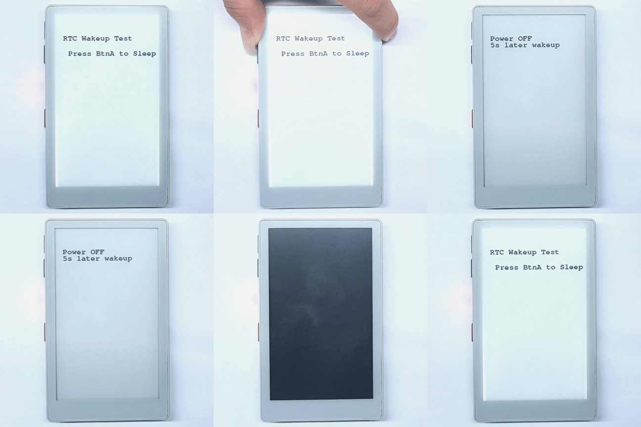
案例说明:设备开机后,单击按键 A 配置 RTC 定时器唤醒,M5PM1 进入休眠。 5s 后触发 RTC 唤醒,ESP32-S3 重新上电。
#include <M5Unified.h>
#include <M5PM1.h>

M5PM1 pm1;

void setup(void)
{
    auto cfg = M5.config();
    cfg.clear_display = false;
    M5.begin(cfg);
    Serial.begin(115200);

    // Initialize PM1
    m5pm1_err_t err = pm1.begin(&M5.In_I2C, M5PM1_DEFAULT_ADDR, M5PM1_I2C_FREQ_100K);

    if (err == M5PM1_OK) {
        Serial.println("PM1 initialization successful");
        pm1.gpioSetWakeEnable(M5PM1_GPIO_NUM_0, true);
        pm1.gpioSetWakeEdge(M5PM1_GPIO_NUM_0, M5PM1_GPIO_WAKE_FALLING);  // Falling edge
    } else {
        Serial.printf("PM1 initialization failed, error code: %d\n", err);
    }

    M5.Display.setEpdMode(epd_mode_t::epd_fast);
    M5.Display.setFont(&fonts::FreeMonoBold18pt7b);
    M5.Display.clear();
    M5.Display.setCursor(40, 100);
    M5.Display.printf("RTC Wakeup Test\n\n");
    M5.Display.println("   Press BtnA to Sleep");
}

void loop(void)
{
    M5.update();
    if (M5.BtnA.wasPressed()) {
        M5.Rtc.clearIRQ();

        if (M5.Rtc.setTimerIRQ(5000)){// 5s later wakeup
            Serial.println("RTC IRQ enabled successfully");
            M5.Display.clear();
            M5.Display.setCursor(40, 100);
            M5.Display.printf("Power OFF");
            M5.Display.setCursor(40, 130);
            M5.Display.printf("5s later wakeup");
            // Shutdown
            pm1.setLdoEnable(true);
            pm1.ldoSetPowerHold(true);
            pm1.setLedEnLevel(true);
            delay(500);
            pm1.shutdown();
        } else {
            Serial.println("Failed to enable RTC IRQ");
        }
    }
}按下按键 A 后,程序会清除 RTC 中断并设置 5 秒定时器,同时保持 M5PM1 的 L1 供电后关闭整机。定时器到期时,RTC 通过 M5PM1 GPIO0 触发下降沿唤醒,M5PM1 恢复供电,ESP32-S3 重新执行初始化。
RTC ESP32-S3 唤醒
RTC 唤醒配置步骤与 IMU ESP32-S3 唤醒类似,区别在于 RTC 唤醒不需要像 IMU 那样配置 BMI270 中断,但仍依赖 RTC IRQ → M5PM1 GPIO → PYG1_IRQ → ESP32-S3 G1 这条链路。
#include <M5Unified.h>
#include <M5PM1.h>
#include "driver/rtc_io.h"

M5PM1 pm1;

void setup(void) {
  auto cfg = M5.config();
    cfg.clear_display = false;
    cfg.disable_rtc_irq = false;
    M5.begin(cfg);
    Serial.begin(115200);

    // Initialize PM1
    m5pm1_err_t err = pm1.begin(&M5.In_I2C, M5PM1_DEFAULT_ADDR, M5PM1_I2C_FREQ_100K);

    if (err == M5PM1_OK) {
        Serial.println("PM1 initialization successful");
        pm1.irqClearGpioAll();
        pm1.irqClearSysAll();
        pm1.irqClearBtnAll();

        pm1.irqSetGpioMaskAll(M5PM1_IRQ_MASK_ENABLE);
        pm1.irqSetSysMaskAll(M5PM1_IRQ_MASK_ENABLE);
        pm1.irqSetBtnMaskAll(M5PM1_IRQ_MASK_ENABLE);

        pm1.irqSetGpioMask(M5PM1_IRQ_GPIO0, M5PM1_IRQ_MASK_DISABLE);
        pm1.gpioSetMode(M5PM1_GPIO_NUM_0, M5PM1_GPIO_MODE_INPUT);
        pm1.gpioSetPull(M5PM1_GPIO_NUM_0, M5PM1_GPIO_PULL_UP);

        pm1.gpioSetMode(M5PM1_GPIO_NUM_1, M5PM1_GPIO_MODE_OUTPUT);
        pm1.gpioSetDrive(M5PM1_GPIO_NUM_1, M5PM1_GPIO_DRIVE_PUSHPULL);
        pm1.gpioSetFunc(M5PM1_GPIO_NUM_1, M5PM1_GPIO_FUNC_IRQ);
    } else {
        Serial.printf("PM1 initialization failed, error code: %d\n", err);
    }

    M5.Display.setEpdMode(epd_mode_t::epd_fast);
    M5.Display.setFont(&fonts::FreeMonoBold18pt7b);
    M5.Display.clear();
    M5.Display.setCursor(40, 100);
    M5.Display.printf("RTC IRQ Test\n\n");
    M5.Display.println("   Press BtnA to Sleep");
    delay(200);
    M5.Rtc.clearIRQ();
    delay(200);
}

volatile bool pm1IrqTriggered = false;

void ARDUINO_ISR_ATTR pm1_irq_handler() {
    pm1IrqTriggered = true;
}

void loop(void) {
    M5.update();

    if (pm1IrqTriggered) {
        pm1IrqTriggered = false;
        M5.Rtc.clearIRQ();
        M5.Rtc.setTimerIRQ(0);
        pm1.irqClearGpioAll();
        pm1.irqClearSysAll();
        pm1.irqClearBtnAll();
        Serial.println("PM1 IRQ triggered");
        M5.Display.setCursor(40, 140);
        M5.Display.println("PM1 IRQ triggered");
    }

    if (M5.BtnA.wasPressed()) {
        if (M5.Rtc.setTimerIRQ(5000)){// Set Timer IRQ
            Serial.println("RTC IRQ enabled successfully");
            M5.Display.clear();
            M5.Display.setCursor(40, 100);
            M5.Display.printf("Wait for IRQ ...");

            // Choose either of the two pieces of code below.
            pinMode(GPIO_NUM_1, INPUT_PULLUP);
            attachInterrupt(GPIO_NUM_1, pm1_irq_handler, FALLING);

            // esp_sleep_enable_ext0_wakeup(GPIO_NUM_1, 0);  // 0 = Low
            // rtc_gpio_pullup_en(GPIO_NUM_1);
            // Serial.println("Going to sleep now");
            // esp_deep_sleep_start();
        } else {
            Serial.println("Failed to enable RTC IRQ");
        }
    }
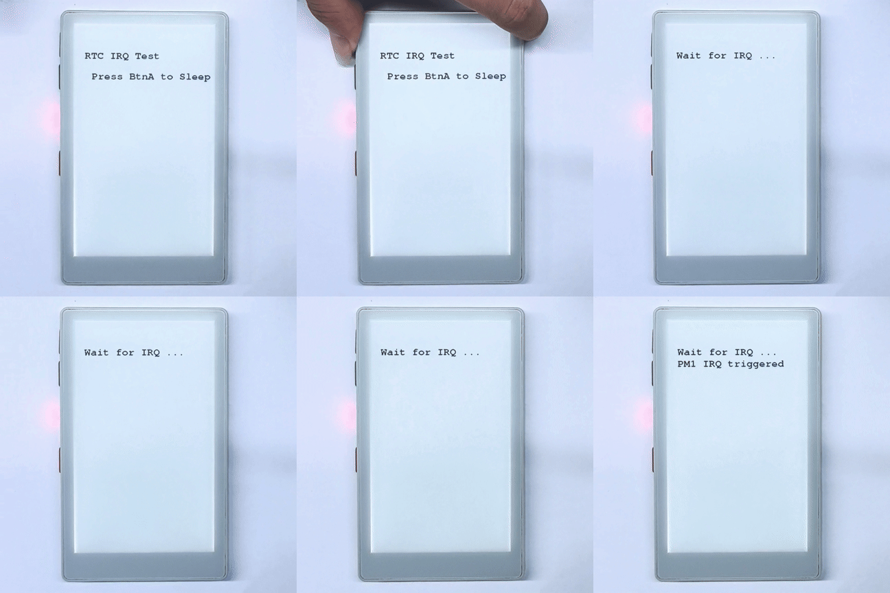
}按下按键 A 后,程序会设置 5 秒 RTC 中断,并通过 M5PM1 将 GPIO0 的中断转发到 ESP32-S3 G1。当前代码默认使用 G1 下降沿中断显示触发结果;若启用代码中注释的深度休眠部分,RTC 定时到期后会唤醒 ESP32-S3,并从 setup() 重新运行。
6. M5IOE1 外设控制
PaperMono 的 M5IOE1 负责 L3B 级外设控制,主要 M5IOE1 引脚如下:
| M5IOE1 引脚 | PaperMono 功能 |
|---|---|
M5IOE1_PIN_2 | LoRa 天线切换 |
M5IOE1_PIN_3 | 电子纸电源 |
M5IOE1_PIN_4 | NFC/RFID 使能 |
M5IOE1_PIN_5 | 电子纸复位 |
M5IOE1_PIN_6 | 触摸复位 |
M5IOE1_PIN_8 | RGB LED 绿色通道 |
M5IOE1_PIN_9 | RGB LED 蓝色通道 |
M5IOE1_PIN_10 | LoRa 复位 |
M5IOE1_PIN_12 | PDM 麦克风电源 |
M5IOE1_PIN_13 | 触摸电源 |
M5IOE1_PIN_14 | microSD 电源 |
下面示例直接初始化 M5PM1 与 M5IOE1,依次演示屏幕前光、LoRa 天线开关与复位、NFC 供电,以及 RGB LED 绿色和蓝色通道控制。电子纸、触摸、microSD 和 PDM 相关引脚已经被 M5Unified 使用,修改它们前应确保对应外设已经停止,否则可能导致外设失效或需要重新初始化。
#include <M5Unified.h>
#include <M5PM1.h>
#include <M5IOE1.h>

M5PM1 pm1;
M5IOE1 ioe1;

#define IOE_LORA_ANT_SW M5IOE1_PIN_2
#define IOE_LORA_RST    M5IOE1_PIN_10
#define IOE_NFC_EN      M5IOE1_PIN_4
#define IOE_LED_G       M5IOE1_PIN_8
#define IOE_LED_B       M5IOE1_PIN_9

void setup(void)
{
    auto cfg = M5.config();
    cfg.clear_display = false;
    M5.begin(cfg);
    Serial.begin(115200);

    // Initialize PM1.
    const m5pm1_err_t pm1_err =
        pm1.begin(&M5.In_I2C, M5PM1_DEFAULT_ADDR, M5PM1_I2C_FREQ_100K);
    if (pm1_err == M5PM1_OK) {
        Serial.println("PM1 initialization successful");
    } else {
        Serial.printf("PM1 initialization failed, error code: %d\n", pm1_err);
    }
    pm1.setSingleResetDisable(false);

    // Enable the PaperMono LoRa power rail through PM1 GPIO2.
    pm1.gpioSetFunc(M5PM1_GPIO_NUM_2, M5PM1_GPIO_FUNC_GPIO);
    pm1.gpioSetMode(M5PM1_GPIO_NUM_2, M5PM1_GPIO_MODE_OUTPUT);
    pm1.gpioSetDrive(M5PM1_GPIO_NUM_2, M5PM1_GPIO_DRIVE_PUSHPULL);
    pm1.gpioSetOutput(M5PM1_GPIO_NUM_2, true);

    // Initialize IOE1.
    const m5ioe1_err_t ioe1_err =
        ioe1.begin(&M5.In_I2C, M5IOE1_DEFAULT_ADDR, M5IOE1_I2C_FREQ_100K);
    if (ioe1_err == M5IOE1_OK) {
        Serial.println("IOE1 initialization successful");
    } else {
        Serial.printf("IOE1 initialization failed, error code: %d\n", ioe1_err);
        while (true) delay(1000);
    }

    ioe1.pinMode(IOE_LORA_ANT_SW, OUTPUT);
    ioe1.pinMode(IOE_LORA_RST, OUTPUT);
    ioe1.pinMode(IOE_NFC_EN, OUTPUT);
    ioe1.pinMode(IOE_LED_G, OUTPUT);
    ioe1.pinMode(IOE_LED_B, OUTPUT);

    // Default states: LoRa receive path, LoRa released from reset, NFC on, LEDs off.
    ioe1.digitalWrite(IOE_LORA_ANT_SW, LOW);
    ioe1.digitalWrite(IOE_LORA_RST, HIGH);
    ioe1.digitalWrite(IOE_NFC_EN, HIGH);
    ioe1.digitalWrite(IOE_LED_G, LOW);
    ioe1.digitalWrite(IOE_LED_B, LOW);

    M5.Display.setEpdMode(epd_mode_t::epd_fast);
    M5.Display.setFont(&fonts::FreeMonoBold18pt7b);
    M5.Display.clear();
    M5.Display.setCursor(40, 100);
    M5.Display.printf("IOE1 Power Test Begin\n\n");
    delay(1000);
}

void loop(void)
{
    M5.update();

    // Display frontlight.
    M5.Display.clear();
    M5.Display.setCursor(40, 100);
    M5.Display.printf("Frontlight OFF");
    M5.Display.setBrightness(0);
    delay(1000);
    M5.Display.setBrightness(255);
    M5.Display.setCursor(40, 140);
    M5.Display.printf("Frontlight ON");
    delay(1000);

    // LoRa antenna switch.
    M5.Display.clear();
    M5.Display.setCursor(40, 100);
    M5.Display.printf("LoRa antenna RX");
    ioe1.digitalWrite(IOE_LORA_ANT_SW, LOW);
    delay(1000);
    M5.Display.setCursor(40, 140);
    M5.Display.printf("LoRa antenna TX");
    ioe1.digitalWrite(IOE_LORA_ANT_SW, HIGH);
    delay(1000);

    // LoRa reset.
    M5.Display.clear();
    M5.Display.setCursor(40, 100);
    M5.Display.printf("LoRa reset LOW");
    ioe1.digitalWrite(IOE_LORA_RST, LOW);
    delay(100);
    M5.Display.setCursor(40, 140);
    M5.Display.printf("LoRa reset HIGH");
    ioe1.digitalWrite(IOE_LORA_RST, HIGH);
    delay(1000);

    // NFC power enable.
    M5.Display.clear();
    M5.Display.setCursor(40, 100);
    M5.Display.printf("NFC power OFF");
    ioe1.digitalWrite(IOE_NFC_EN, LOW);
    delay(1000);
    M5.Display.setCursor(40, 140);
    M5.Display.printf("NFC power ON");
    ioe1.digitalWrite(IOE_NFC_EN, HIGH);
    delay(1000);

    // RGB LED green and blue channels.
    M5.Display.clear();
    M5.Display.setCursor(40, 100);
    M5.Display.printf("Green LED ON");
    ioe1.digitalWrite(IOE_LED_G, HIGH);
    ioe1.digitalWrite(IOE_LED_B, LOW);
    delay(1000);
    M5.Display.setCursor(40, 140);
    M5.Display.printf("Blue LED ON");
    ioe1.digitalWrite(IOE_LED_G, LOW);
    ioe1.digitalWrite(IOE_LED_B, HIGH);
    delay(1000);
    ioe1.digitalWrite(IOE_LED_G, LOW);
    ioe1.digitalWrite(IOE_LED_B, LOW);
    delay(200);
}成功烧录后,程序会先关闭再开启屏幕前光,然后依次演示 LoRa 天线开关、LoRa 复位、NFC 供电以及 RGB LED 绿色和蓝色通道控制。