

Arduino Quick Start
2. Devices & Examples
3. M5Unified
4. M5GFX
5. Extensions
Unit
Module
Atomic
Tab5
IoT
Accessories
Module13.2 LoRa-1262 Arduino Tutorial
1. Preparations
- Environment Setup: Refer to the Arduino IDE Getting Started Guide to complete IDE installation, and install the corresponding board manager and required driver libraries for the development board used.
- Required Driver Libraries:
- Required Hardware Products:


2. Notes
Antenna Connection
Before using the LoRa module, connect a matching external antenna. Transmitting without an antenna is prohibited, as it may permanently damage the hardware.
I2C Address
The IO expander address can be set using the A and B DIP switches of SW2, as shown below.
| A | B | I2C Address |
|---|---|---|
| 0 | 0 | 0x74 |
| 1 | 0 | 0x73 |
| 0 | 1 | 0x72 |
| 1 | 1 | 0x71 |
Pin Compatibility
Since pin configurations vary across host devices, M5Stack provides a pin compatibility table for reference. Modify the example program according to your actual pin connections.
3. Example Program
- This tutorial uses a CoreS3 with Module13.2 LoRa-1262 for wireless communication. Before use, refer to the image below and set the pin DIP switches to the specified positions.
3.1 Pin DIP Switch
- Module13.2 LoRa-1262 communicates via SPI. Modify the pin definitions in the program according to the actual circuit connections. After connecting the device to CoreS3, the corresponding SPI IO pins are
G1 (NSS),G2 (BUSY),G37 (MOSI),G35 (MISO), andG36 (SCK), the interrupt IO isG10 (IRQ), and the IO expander address is shown in the physical setup below:

3.2 Parameter Configuration
Module13.2 LoRa-1262 supports multiple parameter configurations. Refer to the following information before use. For the meaning of each parameter and other details, see the Datasheet. Adjust the parameters in the example program as needed and ensure that the transmitter and receiver use matching parameters.
Frequency (LORA_FREQ)
- Module13.2 LoRa-1262 supports the
868 ~ 923 MHzband. Select a frequency according to the radio regulations in your region. - The transmitter and receiver must use the same frequency.
Bandwidth (LORA_BW)
- The unit is kHz. A smaller bandwidth generally improves receive sensitivity and long-distance communication capability, but lowers the data rate and increases packet airtime. A larger bandwidth increases the data rate, but may reduce noise immunity and communication range.
Spreading Factor (LORA_SF)
- The configurable range is 6 ~ 12.
- A larger value generally improves receive sensitivity and interference immunity, but lowers the transmission rate and increases packet airtime.
- The transmitter and receiver must use the same spreading factor.
Coding Rate (LORA_CR)
- The configurable range is 5 ~ 8, corresponding to coding rates
4/5~4/8. - A larger value provides stronger error correction, but lowers the effective data rate and increases packet airtime.
Sync Word (LORA_SYNC_WORD)
- Used to distinguish different LoRa networks.
- The receiver can correctly identify a packet only when the sync words match. The transmitter and receiver must use the same sync word.
Transmit Power (LORA_TX_POWER)
- The configurable range is -9 ~ 22 dBm.
- A larger value generally increases transmit power and communication range, but also increases power consumption and power supply requirements.
Note:
1. If a stable power supply is unavailable, such as when using a CoreS3 battery base, set a lower power value; otherwise, the module may not work properly.
2. This parameter has no practical effect on the receiver and is only used to allow the software to compile successfully.
2. This parameter has no practical effect on the receiver and is only used to allow the software to compile successfully.
Preamble Length (LORA_PREAMBLE_LEN)
- The preamble helps the receiver detect the start of a packet. Increasing its length appropriately can help with weak-signal reception, but increases packet airtime.
- The transmitter and receiver should use the same setting.
Note
The code below sets only the
NSS, IRQ, and BUSY pins. The RadioLib library automatically maps the remaining SPI pins (MOSI, MISO, and SCK) according to the controller being used. When initialized with M5Unified, the default pins are defined for each device, so they do not need to be specified manually.3.3 Transmitter
cpp
1 2 3 4 5 6 7 8 9 10 11 12 13 14 15 16 17 18 19 20 21 22 23 24 25 26 27 28 29 30 31 32 33 34 35 36 37 38 39 40 41 42 43 44 45 46 47 48 49 50 51 52 53 54 55 56 57 58 59 60 61 62 63 64 65 66 67 68 69 70 71 72 73 74 75 76 77 78 79 80 81 82 83 84 85 86 87 88 89 90 91 92 93 94 95 96 97 98 99 100 101 102 103 104 105 106 107 108 109 110 111 112 113 114 115 116 117 118 119 120 121 122 123 124 125 126 127 128 129 130 131 132 133 134 135 136 137 138 139 140 141 142 143 144 145 146 147 148 149 150 151 152 153 154 155 156 157 158 159 160 161 162 163 164 165 166 167 168 169 170 171 172 173 174 175 176 177 178 179 180 181 182 183 184 185 186 187 188 189 190 191 192 193 194
#include <M5Unified.h>
#include <M5IOE1.h>
#include <RadioLib.h>

// M5IOE1 I2C address selected by SW2.
#define IO_EXPANDER_ADDRESS 0x74

// CoreS3 pins selected by the module DIP switches.
#define LORA_NSS_PIN  GPIO_NUM_1
#define LORA_BUSY_PIN GPIO_NUM_2
#define LORA_IRQ_PIN  GPIO_NUM_10

// M5IOE1 pins for LoRa reset, bypass, and power control.
#define PY_IO2_LORA_RST   M5IOE1_PIN_2
#define PY_IO3_BYPASS     M5IOE1_PIN_3
#define PY_IO5_PWR_EN     M5IOE1_PIN_5

// LoRa parameters. These values must match on both devices.
#define LORA_FREQ         868.0f  // Carrier frequency (MHz).
#define LORA_BW           125.0f  // Bandwidth (kHz).
#define LORA_SF           12      // Spreading factor.
#define LORA_CR           5       // Coding rate: 4/5.
#define LORA_SYNC_WORD    0x34    // Sync word.
#define LORA_TX_POWER     22      // TX power (dBm).
#define LORA_CURRENT_LIMIT 140.0f // TX current limit (mA).
#define LORA_PREAMBLE_LEN 20      // Preamble length (symbols).

// SX1262 pins: NSS, IRQ, reset (controlled by M5IOE1), and BUSY.
SX1262 radio = new Module(LORA_NSS_PIN, LORA_IRQ_PIN, RADIOLIB_NC, LORA_BUSY_PIN);
M5Canvas canvas(&M5.Lcd);
M5IOE1 ioe1;

int transmissionState = RADIOLIB_ERR_NONE;
volatile bool transmittedFlag = false;

bool setExpanderOutput(uint8_t pin, uint8_t level)
{
    // Configure one M5IOE1 pin as a push-pull output and set its level.
    m5ioe1_err_t error = M5IOE1_OK;
    ioe1.pinModeWithRes(pin, OUTPUT, &error);
    if (error != M5IOE1_OK) {
        return false;
    }
    if (ioe1.setDriveMode(pin, M5IOE1_DRIVE_PUSHPULL) != M5IOE1_OK) {
        return false;
    }
    ioe1.digitalWriteWithRes(pin, level, &error);
    return error == M5IOE1_OK;
}

bool initModuleControl()
{
    // Initialize the M5IOE1 control interface.
    const m5ioe1_err_t ioeState = ioe1.begin(
        &M5.In_I2C, IO_EXPANDER_ADDRESS, M5IOE1_I2C_FREQ_100K,
        M5IOE1_INT_MODE_DISABLED);
    if (ioeState != M5IOE1_OK) {
        Serial.printf("M5IOE1 init failed at 0x%02X, code: %d\n",
                      IO_EXPANDER_ADDRESS, ioeState);
        return false;
    }

    // Hold reset, set the bypass control, and disable module power.
    if (!setExpanderOutput(PY_IO2_LORA_RST, LOW) ||
        !setExpanderOutput(PY_IO3_BYPASS, HIGH) ||
        !setExpanderOutput(PY_IO5_PWR_EN, LOW)) {
        return false;
    }
    delay(25);

    // Enable module power before releasing reset.
    if (!setExpanderOutput(PY_IO5_PWR_EN, HIGH)) {
        return false;
    }
    delay(120);

    // Release reset after the power rail is stable.
    if (!setExpanderOutput(PY_IO2_LORA_RST, HIGH)) {
        return false;
    }
    delay(120);
    return true;
}

void IRAM_ATTR setFlag(void)
{
    // Mark the packet-sent event for loop().
    transmittedFlag = true;
}

void showSending(const String& payload, int count)
{
    canvas.clear();
    canvas.setCursor(0, 5);
    canvas.printf("[SX1262]\nSending #%d packet......\n", count);
    canvas.printf("Data:\n %s\n", payload.c_str());
    canvas.pushSprite(0, 0);
}

void setup()
{
    auto cfg = M5.config();
    M5.begin(cfg);
    Serial.begin(115200);
    canvas.createSprite(320, 240);
    canvas.setFont(&fonts::FreeMonoBold9pt7b);

    if (!initModuleControl()) {
        Serial.println(F("IO_EXP init failed"));
        canvas.println(F("IO_EXP init failed"));
        canvas.pushSprite(0, 0);
        while (true) {
            delay(1000);
        }
    }

    // Initialize the SX1262.
    Serial.print(F("[SX1262] Initializing ... "));
    int state = radio.begin(LORA_FREQ, LORA_BW, LORA_SF, LORA_CR,
                            LORA_SYNC_WORD, LORA_TX_POWER, LORA_PREAMBLE_LEN,
                            3.0f, true);
    if (state != RADIOLIB_ERR_NONE) {
        Serial.print(F("failed, code "));
        Serial.println(state);
        canvas.println(F("SX1262 init failed"));
        canvas.pushSprite(0, 0);
        while (true) {
            delay(1000);
        }
    }
    state = radio.setCurrentLimit(LORA_CURRENT_LIMIT);
    if (state != RADIOLIB_ERR_NONE) {
        Serial.print(F("current limit setup failed, code "));
        Serial.println(state);
        canvas.println(F("Current limit setup failed"));
        canvas.pushSprite(0, 0);
        while (true) {
            delay(1000);
        }
    }
    Serial.println(F("success!"));

    // Register the callback for the packet-sent interrupt.
    radio.setPacketSentAction(setFlag);
    // Send an initial packet to start interrupt-driven transmission.
    Serial.print(F("[SX1262] Sending first packet ... "));
    transmissionState = radio.startTransmit("Transmitter Ready");
    if (transmissionState != RADIOLIB_ERR_NONE) {
        Serial.print(F("startTransmit failed, code: "));
        Serial.println(transmissionState);
    }
    canvas.clear();
    canvas.setCursor(0, 5);
    canvas.println(F("[SX1262]"));
    canvas.println(F("Transmitter Ready"));
    canvas.pushSprite(0, 0);
}

int count = 0;

void loop()
{
    // Wait until the packet-sent interrupt is received.
    if (!transmittedFlag) {
        return;
    }
    transmittedFlag = false;

    if (transmissionState == RADIOLIB_ERR_NONE) {
        Serial.println(F("Transmission finished!"));
        canvas.println(F("Send successfully!"));
        canvas.pushSprite(0, 0);
    } else {
        Serial.print(F("Send failed, code: "));
        Serial.println(transmissionState);
        canvas.println(F("Send failed"));
        canvas.printf("code: %d\n", transmissionState);
        canvas.pushSprite(0, 0);
    }

    // Finish the previous transmission before starting the next one.
    radio.finishTransmit();
    delay(1000);

    // Start the next packet.
    String payload = "Module13.2 LoRa-1262 #" + String(count);
    Serial.printf("[SX1262] Sending #%d packet ... ", count);
    transmissionState = radio.startTransmit(payload);
    if (transmissionState != RADIOLIB_ERR_NONE) {
        Serial.print(F("startTransmit failed, code: "));
        Serial.println(transmissionState);
    }
    showSending(payload, count++);
}3.4 Receiver
cpp
1 2 3 4 5 6 7 8 9 10 11 12 13 14 15 16 17 18 19 20 21 22 23 24 25 26 27 28 29 30 31 32 33 34 35 36 37 38 39 40 41 42 43 44 45 46 47 48 49 50 51 52 53 54 55 56 57 58 59 60 61 62 63 64 65 66 67 68 69 70 71 72 73 74 75 76 77 78 79 80 81 82 83 84 85 86 87 88 89 90 91 92 93 94 95 96 97 98 99 100 101 102 103 104 105 106 107 108 109 110 111 112 113 114 115 116 117 118 119 120 121 122 123 124 125 126 127 128 129 130 131 132 133 134 135 136 137 138 139 140 141 142 143 144 145 146 147 148 149 150 151 152 153 154 155 156 157 158 159 160 161 162 163 164 165 166 167 168 169 170 171 172 173 174 175 176 177 178 179 180 181 182 183 184 185 186 187 188 189 190 191 192 193 194 195 196 197 198 199 200 201 202 203 204
#include <M5Unified.h>
#include <M5IOE1.h>
#include <RadioLib.h>

// M5IOE1 I2C address selected by SW2.
#define IO_EXPANDER_ADDRESS 0x74

// CoreS3 pins selected by the module DIP switches.
#define LORA_NSS_PIN  GPIO_NUM_1
#define LORA_BUSY_PIN GPIO_NUM_2
#define LORA_IRQ_PIN  GPIO_NUM_10

// M5IOE1 pins for LoRa reset, bypass, and power control.
#define PY_IO2_LORA_RST   M5IOE1_PIN_2
#define PY_IO3_BYPASS     M5IOE1_PIN_3
#define PY_IO5_PWR_EN     M5IOE1_PIN_5

// LoRa parameters. These values must match on both devices.
#define LORA_FREQ         868.0f  // Carrier frequency (MHz).
#define LORA_BW           125.0f  // Bandwidth (kHz).
#define LORA_SF           12      // Spreading factor.
#define LORA_CR           5       // Coding rate: 4/5.
#define LORA_SYNC_WORD    0x34    // Sync word.
#define LORA_TX_POWER     22      // TX power (dBm).
#define LORA_CURRENT_LIMIT 140.0f // TX current limit (mA).
#define LORA_PREAMBLE_LEN 20      // Preamble length (symbols).

// SX1262 pins: NSS, IRQ, reset (controlled by M5IOE1), and BUSY.
SX1262 radio = new Module(LORA_NSS_PIN, LORA_IRQ_PIN, RADIOLIB_NC, LORA_BUSY_PIN);
M5Canvas canvas(&M5.Lcd);
M5IOE1 ioe1;

// Set by the packet-received interrupt.
volatile bool receivedFlag = false;

bool setExpanderOutput(uint8_t pin, uint8_t level)
{
    // Configure one M5IOE1 pin as a push-pull output and set its level.
    m5ioe1_err_t error = M5IOE1_OK;
    ioe1.pinModeWithRes(pin, OUTPUT, &error);
    if (error != M5IOE1_OK) {
        return false;
    }
    if (ioe1.setDriveMode(pin, M5IOE1_DRIVE_PUSHPULL) != M5IOE1_OK) {
        return false;
    }
    ioe1.digitalWriteWithRes(pin, level, &error);
    return error == M5IOE1_OK;
}

bool initModuleControl()
{
    // Initialize the M5IOE1 control interface.
    const m5ioe1_err_t ioeState = ioe1.begin(
        &M5.In_I2C, IO_EXPANDER_ADDRESS, M5IOE1_I2C_FREQ_100K,
        M5IOE1_INT_MODE_DISABLED);
    if (ioeState != M5IOE1_OK) {
        Serial.printf("M5IOE1 init failed at 0x%02X, code: %d\n",
                      IO_EXPANDER_ADDRESS, ioeState);
        return false;
    }

    // Hold reset, set the bypass control, and disable module power.
    if (!setExpanderOutput(PY_IO2_LORA_RST, LOW) ||
        !setExpanderOutput(PY_IO3_BYPASS, HIGH) ||
        !setExpanderOutput(PY_IO5_PWR_EN, LOW)) {
        return false;
    }
    delay(25);

    // Enable module power before releasing reset.
    if (!setExpanderOutput(PY_IO5_PWR_EN, HIGH)) {
        return false;
    }
    delay(120);

    // Release reset after the power rail is stable.
    if (!setExpanderOutput(PY_IO2_LORA_RST, HIGH)) {
        return false;
    }
    delay(120);
    return true;
}

void IRAM_ATTR setFlag(void)
{
    // Mark the packet-received event for loop().
    receivedFlag = true;
}

void setup()
{
    auto cfg = M5.config();
    M5.begin(cfg);
    Serial.begin(115200);
    canvas.createSprite(320, 240);
    canvas.setFont(&fonts::FreeMonoBold9pt7b);

    if (!initModuleControl()) {
        Serial.println(F("IO_EXP init failed"));
        canvas.println(F("IO_EXP init failed"));
        canvas.pushSprite(0, 0);
        while (true) {
            delay(1000);
        }
    }

    // Initialize the SX1262.
    Serial.print(F("[SX1262] Initializing ... "));
    int state = radio.begin(LORA_FREQ, LORA_BW, LORA_SF, LORA_CR,
                            LORA_SYNC_WORD, LORA_TX_POWER, LORA_PREAMBLE_LEN,
                            3.0f, true);
    if (state != RADIOLIB_ERR_NONE) {
        Serial.print(F("failed, code "));
        Serial.println(state);
        canvas.println(F("SX1262 init failed"));
        canvas.pushSprite(0, 0);
        while (true) {
            delay(1000);
        }
    }
    state = radio.setCurrentLimit(LORA_CURRENT_LIMIT);
    if (state != RADIOLIB_ERR_NONE) {
        Serial.print(F("current limit setup failed, code "));
        Serial.println(state);
        canvas.println(F("Current limit setup failed"));
        canvas.pushSprite(0, 0);
        while (true) {
            delay(1000);
        }
    }
    Serial.println(F("success!"));

    // Register the callback for the packet-received interrupt.
    radio.setPacketReceivedAction(setFlag);
    // Start interrupt-driven receive mode.
    Serial.print(F("[SX1262] Starting to listen ... "));
    state = radio.startReceive();
    if (state != RADIOLIB_ERR_NONE) {
        Serial.print(F("failed, code "));
        Serial.println(state);
        canvas.println(F("Receive start failed"));
        canvas.pushSprite(0, 0);
        while (true) {
            delay(1000);
        }
    }
    Serial.println(F("success!"));

    canvas.setCursor(0, 5);
    canvas.println(F("[SX1262]"));
    canvas.println(F("Waiting for packet..."));
    canvas.pushSprite(0, 0);
}

void loop()
{
    // Wait until the packet-received interrupt is received.
    if (!receivedFlag) {
        return;
    }
    receivedFlag = false;

    // Read the packet after the interrupt is received.
    String payload;
    int state = radio.readData(payload);
    if (state == RADIOLIB_ERR_NONE) {
        // Read link quality information for the received packet.
        const float rssi = radio.getRSSI();
        const float snr = radio.getSNR();
        const float frequencyError = radio.getFrequencyError();

        Serial.println(F("[SX1262] Received packet:"));
        Serial.print(F("[SX1262] Data:\t\t"));
        Serial.println(payload);
        Serial.print(F("[SX1262] RSSI:\t\t"));
        Serial.print(rssi);
        Serial.println(F(" dBm"));
        Serial.print(F("[SX1262] SNR:\t\t"));
        Serial.print(snr);
        Serial.println(F(" dB"));
        Serial.print(F("[SX1262] Frequency error:\t"));
        Serial.print(frequencyError);
        Serial.println(F(" Hz"));

        canvas.clear();
        canvas.setCursor(0, 5);
        canvas.printf("[SX1262]\nReceived packet:\n");
        canvas.printf("Data:\n %s\n", payload.c_str());
        canvas.printf("RSSI: %0.2f dBm\n", rssi);
        canvas.printf("SNR: %0.2f dB\n", snr);
        canvas.printf("Freq err: %0.2f Hz\n", frequencyError);
        canvas.pushSprite(0, 0);
    } else if (state == RADIOLIB_ERR_CRC_MISMATCH) {
        Serial.println(F("[SX1262] CRC error!"));
    } else {
        Serial.print(F("[SX1262] Receive failed, code: "));
        Serial.println(state);
    }

    // Return to continuous receive mode.
    radio.finishReceive();
    radio.startReceive();
}4. Compile and Upload
- 1. Enter download mode: Press and hold the CoreS3 reset button for about 2 seconds until the internal green LED lights up, then release the button. The green LED turns off after release, indicating that the device has entered download mode and is ready for flashing.
Note
Different devices need to enter download mode before flashing, and the procedure may vary depending on the main controller. For details, refer to the list of device flashing tutorials at the bottom of the Arduino IDE Getting Started Guide page.
.gif)
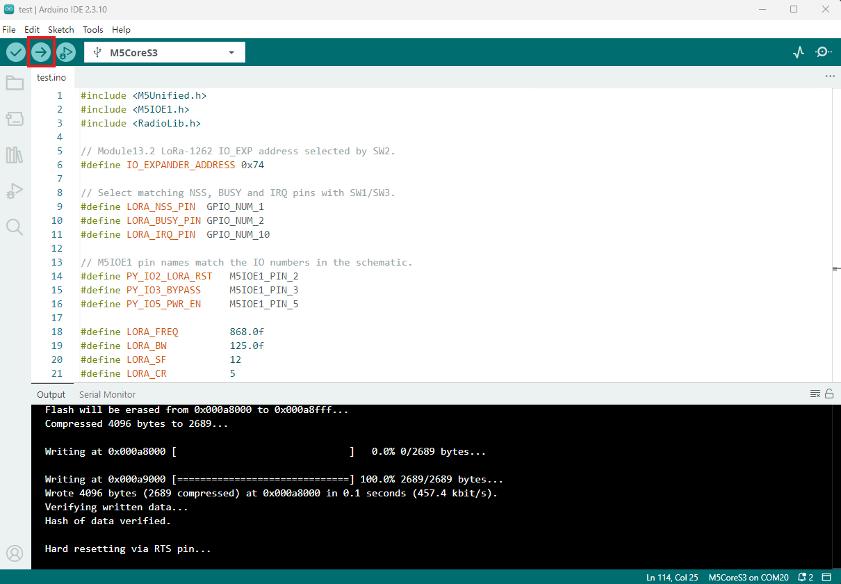
- 2. Select the device port, click the compile and upload button in the upper-left corner of Arduino IDE, and wait for the program to finish compiling and uploading to the device.
5. Information Transmission and Reception Demonstration
The transmitter sends a string containing a counter every second. The receiver prints the received string and displays RSSI and other information.

- Transmitter serial output:
[SX1262] Sending #34 packet ... Transmission finished!- Receiver serial output:
[SX1262] Received packet:
[SX1262] Data:           Module13.2 LoRa-1262 #34
[SX1262] RSSI:           -0.00 dBm
[SX1262] SNR:            5.00 dB
[SX1262] Frequency error: 23.01 HzPage Tools