Arduino Quick Start
2. Devices & Examples
3. M5Unified
4. M5GFX
5. Extensions
Unit
Module
Atomic
Tab5
IoT
Accessories
Unit 8Servos2-Chain Arduino Tutorial
1. Preparation
Environment setup: Refer to the Arduino IDE Getting Started Tutorial to complete the IDE installation, then install the board packages and driver libraries required by the development board you are using.
Libraries used:
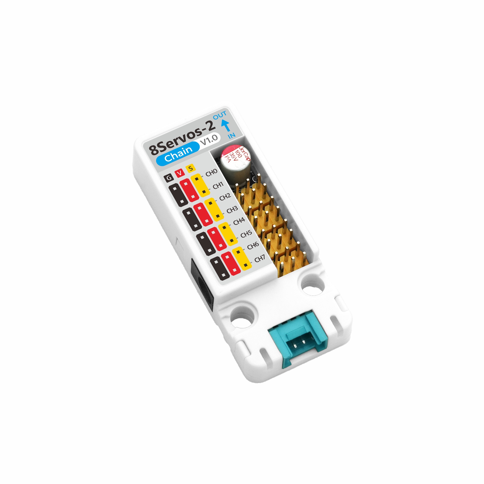
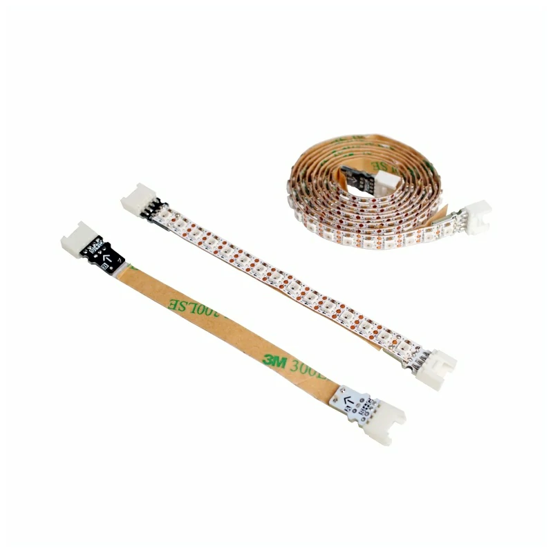
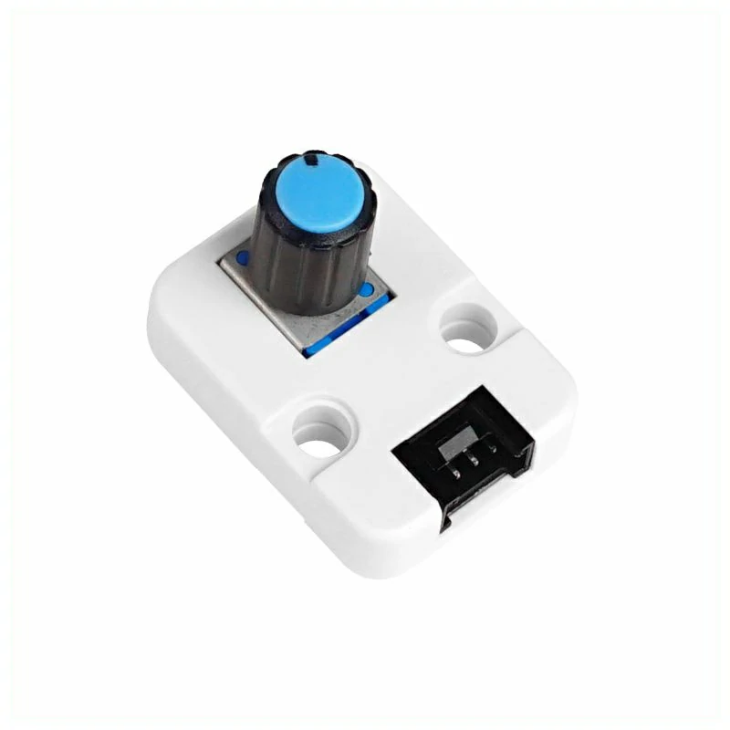
Hardware products used:

2. Notes
3. Example Programs
- This tutorial uses CoreS3 as the host device and Unit 8Servos2-Chain to control servos. Unit 8Servos2-Chain communicates with the host through a serial port. After the devices are connected, the corresponding pins are
G17 (TXD)andG18 (RXD).
cfg.output_power to true in setup().3.1 Servo Control
#include <M5Unified.h>
#include "M5Chain.h"

#define TXD_PIN             17
#define RXD_PIN             18
#define SERVO_CHANNEL_COUNT 8
#define ANGLE_STEP          20
#define LOOP_DELAY_MS       200

// Chain state and device list.
Chain M5Chain;
device_list_t *devices_list = nullptr;
uint16_t device_nums = 0;
uint8_t operation_status = 0;
uint8_t angle = 0;
bool servo_ready = false;
M5Canvas canvas(&M5.Display);

void showMessage(const char *message)
{
    // Show a status message on the display.
    canvas.clear();
    canvas.setCursor(0, 0);
    canvas.println(message);
    canvas.pushSprite(0, 0);
}

bool updateDeviceList()
{
    // Discover all devices on the Chain bus.
    if (!M5Chain.isDeviceConnected()) {
        Serial.println("Chain device not connected");
        return false;
    }

    if (M5Chain.getDeviceNum(&device_nums) != CHAIN_OK || device_nums == 0) {
        Serial.println("Failed to get Chain device count");
        return false;
    }

    // Allocate storage for the device list returned by M5Chain.
    devices_list = (device_list_t *)malloc(sizeof(device_list_t));
    if (devices_list == nullptr) {
        Serial.println("Failed to allocate device list");
        return false;
    }

    devices_list->count = device_nums;
    devices_list->devices = (device_info_t *)malloc(sizeof(device_info_t) * device_nums);
    if (devices_list->devices == nullptr) {
        free(devices_list);
        devices_list = nullptr;
        Serial.println("Failed to allocate device information");
        return false;
    }

    if (!M5Chain.getDeviceList(devices_list)) {
        free(devices_list->devices);
        free(devices_list);
        devices_list = nullptr;
        Serial.println("Failed to get Chain device list");
        return false;
    }

    // Print the detected device IDs and types.
    Serial.printf("Chain device count: %u\r\n", devices_list->count);
    for (uint8_t i = 0; i < devices_list->count; i++) {
        Serial.printf("ID[%u], type: 0x%02X\r\n", devices_list->devices[i].id,
                      devices_list->devices[i].device_type);
    }
    return true;
}

bool initializeServoMode()
{
    if (devices_list == nullptr) {
        return false;
    }

    // Configure all eight channels as servo outputs.
    user_gpio_mode_t modes[SERVO_CHANNEL_COUNT];
    for (uint8_t i = 0; i < SERVO_CHANNEL_COUNT; i++) {
        modes[i] = USER_GPIO_SERVO_MODE;
    }

    bool found = false;
    for (uint8_t i = 0; i < devices_list->count; i++) {
        if (devices_list->devices[i].device_type != UNIT_8SERVOS2_CHAIN_TYPE_CODE) {
            continue;
        }

        found = true;
        uint8_t device_id = devices_list->devices[i].id;
        chain_status_t status = M5Chain.setServosModeAll(
            device_id, modes, SERVO_CHANNEL_COUNT, &operation_status);
        if (status != CHAIN_OK || operation_status != 1) {
            Serial.printf("ID[%u] servo mode setup failed\r\n", device_id);
            continue;
        }

        Serial.printf("ID[%u] servo mode setup success\r\n", device_id);
    }
    return found;
}

bool setAndVerifyAngle(uint8_t target_angle)
{
    if (devices_list == nullptr) {
        return false;
    }

    // Set the same target angle on every servo channel.
    uint8_t target_angles[SERVO_CHANNEL_COUNT];
    uint8_t read_angles[SERVO_CHANNEL_COUNT] = {0};
    for (uint8_t i = 0; i < SERVO_CHANNEL_COUNT; i++) {
        target_angles[i] = target_angle;
    }

    bool all_success = true;
    for (uint8_t i = 0; i < devices_list->count; i++) {
        if (devices_list->devices[i].device_type != UNIT_8SERVOS2_CHAIN_TYPE_CODE) {
            continue;
        }

        uint8_t device_id = devices_list->devices[i].id;
        chain_status_t status = M5Chain.setServosAngleAll(
            device_id, target_angles, SERVO_CHANNEL_COUNT, &operation_status);
        if (status != CHAIN_OK || operation_status != 1 ||
            M5Chain.getServosAngleAll(device_id, read_angles, SERVO_CHANNEL_COUNT) != CHAIN_OK) {
            Serial.printf("ID[%u] angle operation failed\r\n", device_id);
            all_success = false;
            continue;
        }

        // Verify every channel by reading the angle back.
        for (uint8_t channel = 0; channel < SERVO_CHANNEL_COUNT; channel++) {
            if (read_angles[channel] != target_angle) {
                Serial.printf("ID[%u] CH[%u] angle mismatch: %u / %u\r\n",
                              device_id, channel, target_angle, read_angles[channel]);
                all_success = false;
            }
        }
    }
    return all_success;
}

bool readAndDisplayPower(uint8_t current_angle)
{
    if (devices_list == nullptr) {
        return false;
    }

    // Read voltage and current telemetry from each matching device.
    bool all_success = true;
    bool display_updated = false;
    for (uint8_t i = 0; i < devices_list->count; i++) {
        if (devices_list->devices[i].device_type != UNIT_8SERVOS2_CHAIN_TYPE_CODE) {
            continue;
        }

        uint8_t device_id = devices_list->devices[i].id;
        uint16_t dc_voltage = 0;
        uint16_t grove_voltage = 0;
        uint16_t system_current = 0;
        chain_status_t dc_status = M5Chain.getServosDcVoltage(device_id, &dc_voltage);
        chain_status_t grove_status = M5Chain.getServosGroveVoltage(device_id, &grove_voltage);
        chain_status_t current_status = M5Chain.getServosSysCurrent(device_id, &system_current);

        if (dc_status != CHAIN_OK || grove_status != CHAIN_OK || current_status != CHAIN_OK) {
            Serial.printf("ID[%u] power monitor failed: DC=%d, Grove=%d, Current=%d\r\n",
                          device_id, dc_status, grove_status, current_status);
            all_success = false;
            continue;
        }

        Serial.printf("ID[%u] power: DC=%umV, Grove=%umV, Current=%umA\r\n",
                      device_id, dc_voltage, grove_voltage, system_current);

        // Display the first matching device while logging all devices.
        if (!display_updated) {
            canvas.clear();
            canvas.setCursor(0, 0);
            canvas.println("Unit 8Servos2-Chain");
            canvas.setCursor(0, 40);
            canvas.printf("Angle: %u", current_angle);
            canvas.setCursor(0, 80);
            canvas.printf("DC: %umV", dc_voltage);
            canvas.setCursor(0, 120);
            canvas.printf("Current: %umA", system_current);
            canvas.setCursor(0, 160);
            canvas.printf("Grove: %umV", grove_voltage);
            canvas.pushSprite(0, 0);
            display_updated = true;
        }
    }
    return all_success;
}

void setup()
{
    // Disable 5V output on the CoreS3 Grove port.
    auto cfg = M5.config();
    cfg.output_power = false;
    M5.begin(cfg);
    canvas.createSprite(320, 240);
    canvas.setFont(&fonts::FreeMonoBold12pt7b);
    canvas.setTextSize(1);
    Serial.begin(115200);
    Serial.println("Unit 8Servos2-Chain Test");

    // Start Chain UART communication.
    M5Chain.begin(&Serial2, 115200, RXD_PIN, TXD_PIN);
    if (!updateDeviceList()) {
        showMessage("Chain device not found");
        return;
    }

    servo_ready = initializeServoMode();
    if (!servo_ready) {
        showMessage("8Servos2-Chain not found");
        return;
    }
    showMessage("8Servos2-Chain ready");
}

void loop()
{
    if (!servo_ready) {
        delay(LOOP_DELAY_MS);
        return;
    }

    // Set the next angle and verify the response.
    if (setAndVerifyAngle(angle)) {
        Serial.printf("All servo channels set to %u degrees\r\n", angle);
    } else {
        Serial.println("Servo angle operation failed");
    }

    // Update the power monitor display and serial log.
    readAndDisplayPower(angle);

    // Advance through the 0-180 degree test range.
    angle += ANGLE_STEP;
    if (angle > 180) {
        angle = 0;
    }
    delay(LOOP_DELAY_MS);
}After the device is powered on, the program outputs the Chain bus device count, device IDs, and device types to the serial monitor, then searches for Unit 8Servos2-Chain. After the device is found, the program configures all channels as servo mode, cycles through servo angles from 0° to 180° in 20° increments, and reads the DC input voltage, Grove interface voltage, and total system current. When multiple Unit 8Servos2-Chain devices are connected, the serial port outputs the monitoring data for each device, while the display shows the data from the first detected device.
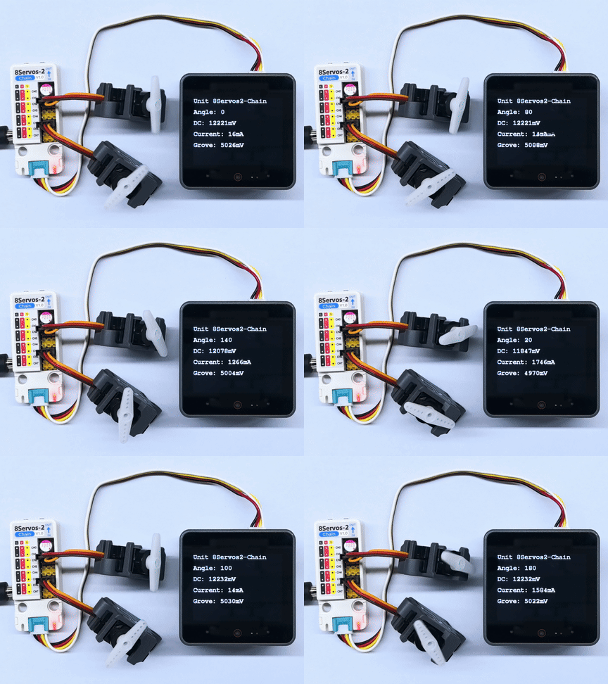
Example serial output:
Unit 8Servos2-Chain Test
Chain device count: 1
ID[1], type: 0x0C
ID[1] servo mode setup success
All servo channels set to 0 degrees
ID[1] power: DC=12254mV, Grove=5046mV, Current=1768mA
All servo channels set to 20 degrees
ID[1] power: DC=12254mV, Grove=5046mV, Current=12mA
All servo channels set to 40 degrees
ID[1] power: DC=12265mV, Grove=5046mV, Current=1700mA
All servo channels set to 60 degrees
ID[1] power: DC=12265mV, Grove=5044mV, Current=12mA
All servo channels set to 80 degrees
ID[1] power: DC=12265mV, Grove=5046mV, Current=1590mA
All servo channels set to 100 degrees
ID[1] power: DC=12254mV, Grove=5044mV, Current=20mA
All servo channels set to 120 degrees
ID[1] power: DC=12243mV, Grove=5008mV, Current=1522mA
All servo channels set to 140 degrees
ID[1] power: DC=12254mV, Grove=5046mV, Current=10mA
All servo channels set to 160 degrees
ID[1] power: DC=12254mV, Grove=5004mV, Current=1488mA
All servo channels set to 180 degrees
ID[1] power: DC=12265mV, Grove=5044mV, Current=12mA3.2 Input and Output Control
#include <M5Unified.h>
#include "M5Chain.h"

#define TXD_PIN       17
#define RXD_PIN       18
#define GPIO_COUNT    8
#define CH0           0
#define CH3           3
#define CH4           4
#define CH7           7
#define LOOP_DELAY_MS 500

// Chain state and device list.
Chain M5Chain;
device_list_t *devices_list = nullptr;
uint16_t device_nums = 0;
uint8_t operation_status = 0;
uint8_t unit_id = 0;
bool unit_ready = false;
bool output_level = false;
M5Canvas canvas(&M5.Display);

void showMessage(const char *message)
{
    // Show a status message on the display.
    canvas.clear();
    canvas.setCursor(0, 0);
    canvas.println(message);
    canvas.pushSprite(0, 0);
}

bool updateDeviceList()
{
    // Discover the Unit 8Servos2-Chain device.
    if (!M5Chain.isDeviceConnected()) {
        Serial.println("Chain device not connected");
        return false;
    }

    if (M5Chain.getDeviceNum(&device_nums) != CHAIN_OK || device_nums == 0) {
        Serial.println("Failed to get Chain device count");
        return false;
    }

    devices_list = (device_list_t *)malloc(sizeof(device_list_t));
    if (devices_list == nullptr) {
        Serial.println("Failed to allocate device list");
        return false;
    }

    devices_list->count = device_nums;
    devices_list->devices = (device_info_t *)malloc(sizeof(device_info_t) * device_nums);
    if (devices_list->devices == nullptr || !M5Chain.getDeviceList(devices_list)) {
        free(devices_list->devices);
        free(devices_list);
        devices_list = nullptr;
        Serial.println("Failed to get Chain device list");
        return false;
    }

    for (uint8_t i = 0; i < devices_list->count; i++) {
        if (devices_list->devices[i].device_type == UNIT_8SERVOS2_CHAIN_TYPE_CODE) {
            unit_id = devices_list->devices[i].id;
            break;
        }
    }
    return unit_id != 0;
}

bool configureChannels()
{
    // Configure CH0 and CH4 as outputs, and CH3 and CH7 as inputs.
    user_gpio_mode_t modes[GPIO_COUNT];
    for (uint8_t i = 0; i < GPIO_COUNT; i++) {
        modes[i] = USER_GPIO_INPUT_MODE;
    }
    modes[CH0] = USER_GPIO_OUTPUT_MODE;
    modes[CH4] = USER_GPIO_OUTPUT_MODE;

    chain_status_t status = M5Chain.setServosModeAll(
        unit_id, modes, GPIO_COUNT, &operation_status);
    if (status != CHAIN_OK || operation_status != 1) {
        return false;
    }

    if (M5Chain.setServosInputPuPd(unit_id, CH3, USER_GPIO_PULL_DOWN, &operation_status) != CHAIN_OK ||
        operation_status != 1) {
        return false;
    }
    if (M5Chain.setServosInputPuPd(unit_id, CH7, USER_GPIO_PULL_DOWN, &operation_status) != CHAIN_OK ||
        operation_status != 1) {
        return false;
    }

    return true;
}

const char *levelName(user_sys_gpio_level_t level)
{
    return level == USER_GPIO_LEVEL_HIGH ? "HIGH" : "LOW";
}

void updateOutputAndDisplay()
{
    // Set CH0 and CH4 to opposite levels at the same update step.
    user_sys_gpio_level_t ch0_level = output_level ? USER_GPIO_LEVEL_HIGH : USER_GPIO_LEVEL_LOW;
    user_sys_gpio_level_t ch4_level = output_level ? USER_GPIO_LEVEL_LOW : USER_GPIO_LEVEL_HIGH;
    bool output_success =
        M5Chain.setServosOutputLevel(unit_id, CH0, ch0_level, &operation_status) == CHAIN_OK &&
        operation_status == 1;
    output_success =
        M5Chain.setServosOutputLevel(unit_id, CH4, ch4_level, &operation_status) == CHAIN_OK &&
        operation_status == 1 && output_success;

    user_sys_gpio_level_t ch3_level = USER_GPIO_LEVEL_LOW;
    user_sys_gpio_level_t ch7_level = USER_GPIO_LEVEL_LOW;
    bool input_success =
        M5Chain.getServosInputLevel(unit_id, CH3, &ch3_level, &operation_status) == CHAIN_OK &&
        operation_status == 1;
    input_success =
        M5Chain.getServosInputLevel(unit_id, CH7, &ch7_level, &operation_status) == CHAIN_OK &&
        operation_status == 1 && input_success;

    canvas.clear();
    canvas.setCursor(0, 0);
    canvas.println("Unit 8Servos2-Chain");
    canvas.setCursor(0, 40);
    canvas.printf("CH0 OUT: %s", levelName(ch0_level));
    canvas.setCursor(0, 80);
    canvas.printf("CH4 OUT: %s", levelName(ch4_level));
    canvas.setCursor(0, 120);
    canvas.printf("CH3 IN:  %s", input_success ? levelName(ch3_level) : "ERROR");
    canvas.setCursor(0, 160);
    canvas.printf("CH7 IN:  %s", input_success ? levelName(ch7_level) : "ERROR");
    canvas.pushSprite(0, 0);

    Serial.printf("CH0=%s, CH4=%s, CH3=%s, CH7=%s\r\n",
                  output_success ? levelName(ch0_level) : "ERROR",
                  output_success ? levelName(ch4_level) : "ERROR",
                  input_success ? levelName(ch3_level) : "ERROR",
                  input_success ? levelName(ch7_level) : "ERROR");
    output_level = !output_level;
}

void setup()
{
    // Disable 5V output on the CoreS3 Grove port.
    auto cfg = M5.config();
    cfg.output_power = false;
    M5.begin(cfg);
    canvas.createSprite(320, 240);
    canvas.setFont(&fonts::FreeMonoBold12pt7b);
    canvas.setTextSize(1);
    Serial.begin(115200);
    Serial.println("Unit 8Servos2-Chain GPIO Test");

    // Start Chain UART communication.
    M5Chain.begin(&Serial2, 115200, RXD_PIN, TXD_PIN);
    if (!updateDeviceList() || !configureChannels()) {
        showMessage("GPIO setup failed");
        return;
    }
    unit_ready = true;
    showMessage("GPIO test ready");
}

void loop()
{
    if (!unit_ready) {
        delay(LOOP_DELAY_MS);
        return;
    }

    updateOutputAndDisplay();
    delay(LOOP_DELAY_MS);
}
After power-on, the program reports the Chain bus device count, device IDs, and device types in the serial monitor, then searches for Unit 8Servos2-Chain. Once found, it configures CH0 and CH4 as outputs and CH3 and CH7 as inputs with pull-down resistors enabled. The program sets CH0 and CH4 to opposite logic levels every 500ms while reading the input levels on CH3 and CH7. The display shows the current output and input states, and the serial port outputs the same data.
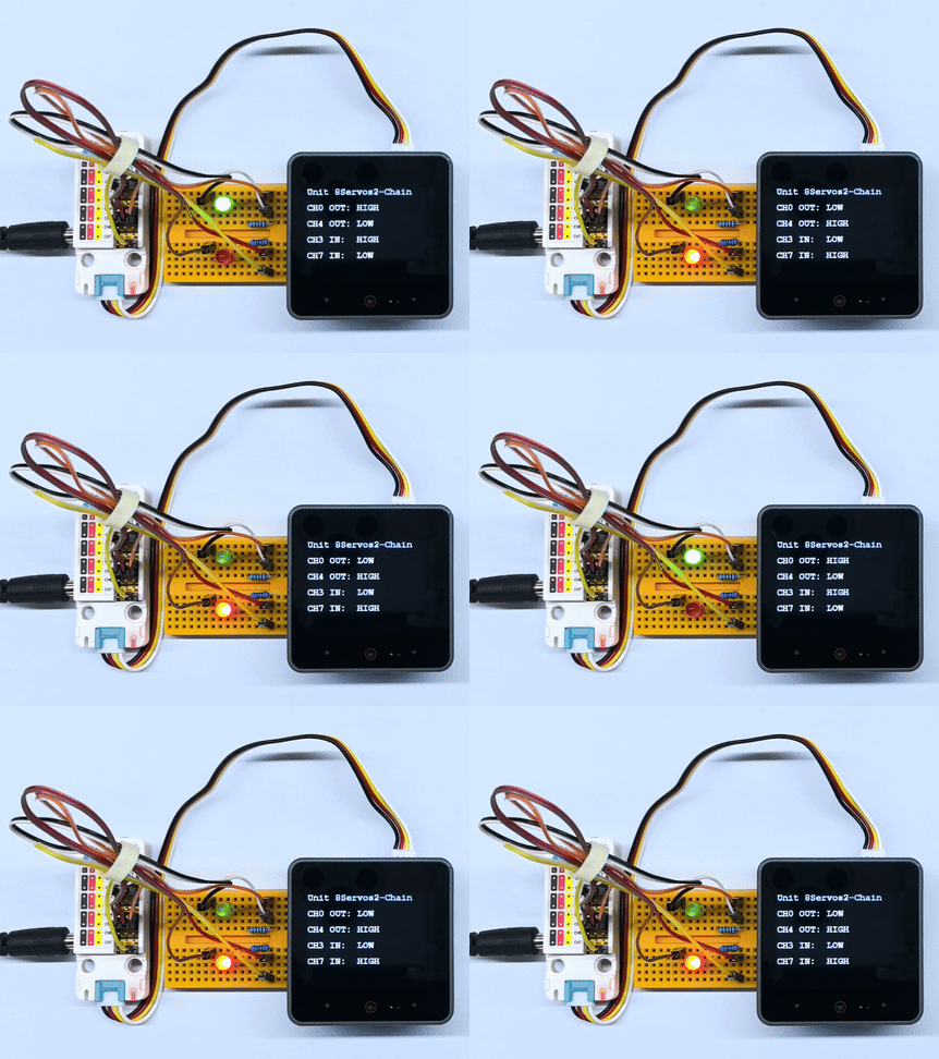
3.3 ADC Acquisition
#include <M5Unified.h>
#include "M5Chain.h"

#define TXD_PIN       17
#define RXD_PIN       18
#define GPIO_COUNT    8
#define ADC_CHANNEL   4
#define LOOP_DELAY_MS 100

// Chain state and device list.
Chain M5Chain;
device_list_t *devices_list = nullptr;
uint16_t device_nums = 0;
uint8_t operation_status = 0;
uint8_t unit_id = 0;
bool unit_ready = false;
M5Canvas canvas(&M5.Display);

void showMessage(const char *message)
{
    // Show a status message on the display.
    canvas.clear();
    canvas.setCursor(0, 0);
    canvas.println(message);
    canvas.pushSprite(0, 0);
}

bool updateDeviceList()
{
    // Discover the Unit 8Servos2-Chain device.
    if (!M5Chain.isDeviceConnected()) {
        Serial.println("Chain device not connected");
        return false;
    }

    if (M5Chain.getDeviceNum(&device_nums) != CHAIN_OK || device_nums == 0) {
        Serial.println("Failed to get Chain device count");
        return false;
    }

    devices_list = (device_list_t *)malloc(sizeof(device_list_t));
    if (devices_list == nullptr) {
        Serial.println("Failed to allocate device list");
        return false;
    }

    devices_list->count = device_nums;
    devices_list->devices = (device_info_t *)malloc(sizeof(device_info_t) * device_nums);
    if (devices_list->devices == nullptr || !M5Chain.getDeviceList(devices_list)) {
        free(devices_list->devices);
        free(devices_list);
        devices_list = nullptr;
        Serial.println("Failed to get Chain device list");
        return false;
    }

    for (uint8_t i = 0; i < devices_list->count; i++) {
        if (devices_list->devices[i].device_type == UNIT_8SERVOS2_CHAIN_TYPE_CODE) {
            unit_id = devices_list->devices[i].id;
            break;
        }
    }
    return unit_id != 0;
}

bool configureAdc()
{
    // Configure CH4 for ADC and keep the other channels as digital inputs.
    user_gpio_mode_t modes[GPIO_COUNT];
    for (uint8_t i = 0; i < GPIO_COUNT; i++) {
        modes[i] = USER_GPIO_INPUT_MODE;
    }
    modes[ADC_CHANNEL] = USER_GPIO_ADC_MODE;

    chain_status_t status = M5Chain.setServosModeAll(
        unit_id, modes, GPIO_COUNT, &operation_status);
    return status == CHAIN_OK && operation_status == 1;
}

void readAndDisplayAdc()
{
    // Read the CH4 ADC value continuously.
    uint16_t adc_value = 0;
    bool success = M5Chain.getServosAdcValue(
                       unit_id, ADC_CHANNEL, &adc_value, &operation_status) == CHAIN_OK &&
                   operation_status == 1;

    canvas.clear();
    canvas.setCursor(0, 0);
    canvas.println("Unit 8Servos2-Chain");
    canvas.setCursor(0, 40);
    canvas.println("ADC monitor");
    canvas.setCursor(0, 80);
    canvas.printf("CH4: %s", success ? "READY" : "ERROR");
    canvas.setCursor(0, 120);
    canvas.printf("Value: %u", adc_value);
    canvas.pushSprite(0, 0);

    Serial.printf("CH4 ADC: %s, value=%u\r\n", success ? "OK" : "ERROR", adc_value);
}

void setup()
{
    // Disable 5V output on the CoreS3 Grove port.
    auto cfg = M5.config();
    cfg.output_power = false;
    M5.begin(cfg);
    canvas.createSprite(320, 240);
    canvas.setFont(&fonts::FreeMonoBold12pt7b);
    canvas.setTextSize(1);
    Serial.begin(115200);
    Serial.println("Unit 8Servos2-Chain ADC Test");

    // Start Chain UART communication.
    M5Chain.begin(&Serial2, 115200, RXD_PIN, TXD_PIN);
    if (!updateDeviceList() || !configureAdc()) {
        showMessage("ADC setup failed");
        return;
    }
    unit_ready = true;
    showMessage("ADC test ready");
}

void loop()
{
    if (!unit_ready) {
        delay(LOOP_DELAY_MS);
        return;
    }

    readAndDisplayAdc();
    delay(LOOP_DELAY_MS);
}
After startup, the program sets CH4 to ADC mode and continuously reads its raw ADC value. The CoreS3 display shows the current channel and ADC value, while the serial port reports the acquisition status and results. The program updates every 100ms.
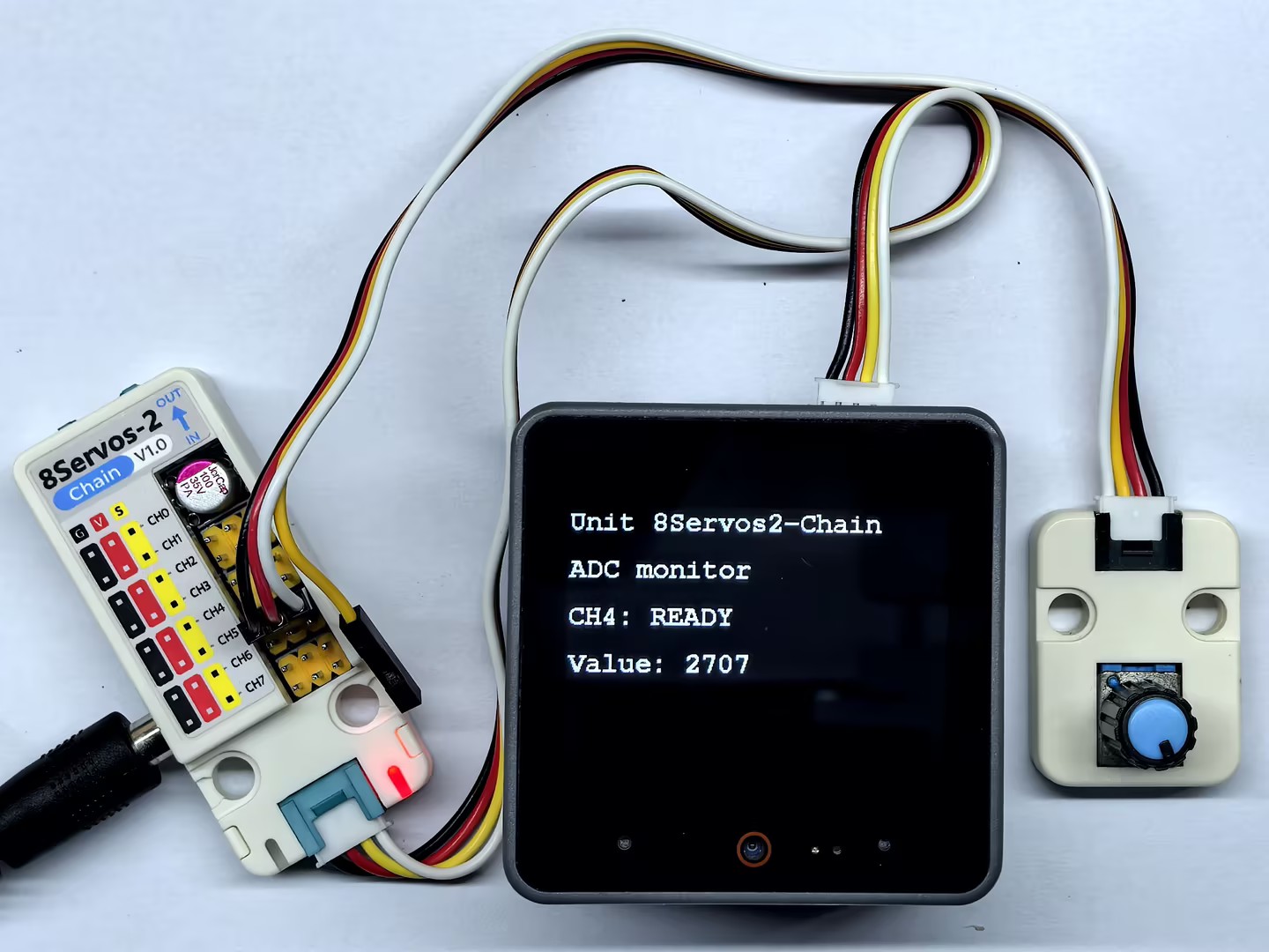
3.4 PWM Output
#include <M5Unified.h>
#include "M5Chain.h"

#define TXD_PIN       17
#define RXD_PIN       18
#define GPIO_COUNT    8
#define CH0           0
#define CH4           4
#define PWM_MAX_DUTY  100
#define DUTY_STEP     10
#define LOOP_DELAY_MS 50

// Chain state and device list.
Chain M5Chain;
device_list_t *devices_list = nullptr;
uint16_t device_nums = 0;
uint8_t operation_status = 0;
uint8_t unit_id = 0;
bool unit_ready = false;
uint8_t ch0_duty = 0;
uint8_t ch4_duty = PWM_MAX_DUTY;
bool duty_increasing = true;
M5Canvas canvas(&M5.Display);

void showMessage(const char *message)
{
    // Show a status message on the display.
    canvas.clear();
    canvas.setCursor(0, 0);
    canvas.println(message);
    canvas.pushSprite(0, 0);
}

bool updateDeviceList()
{
    // Discover the Unit 8Servos2-Chain device.
    if (!M5Chain.isDeviceConnected()) {
        Serial.println("Chain device not connected");
        return false;
    }

    if (M5Chain.getDeviceNum(&device_nums) != CHAIN_OK || device_nums == 0) {
        Serial.println("Failed to get Chain device count");
        return false;
    }

    devices_list = (device_list_t *)malloc(sizeof(device_list_t));
    if (devices_list == nullptr) {
        Serial.println("Failed to allocate device list");
        return false;
    }

    devices_list->count = device_nums;
    devices_list->devices = (device_info_t *)malloc(sizeof(device_info_t) * device_nums);
    if (devices_list->devices == nullptr || !M5Chain.getDeviceList(devices_list)) {
        free(devices_list->devices);
        free(devices_list);
        devices_list = nullptr;
        Serial.println("Failed to get Chain device list");
        return false;
    }

    for (uint8_t i = 0; i < devices_list->count; i++) {
        if (devices_list->devices[i].device_type == UNIT_8SERVOS2_CHAIN_TYPE_CODE) {
            unit_id = devices_list->devices[i].id;
            break;
        }
    }
    return unit_id != 0;
}

bool configurePwm()
{
    // Configure CH0 and CH4 for PWM output.
    user_gpio_mode_t modes[GPIO_COUNT];
    for (uint8_t i = 0; i < GPIO_COUNT; i++) {
        modes[i] = USER_GPIO_INPUT_MODE;
    }
    modes[CH0] = USER_GPIO_PWM_MODE;
    modes[CH4] = USER_GPIO_PWM_MODE;

    chain_status_t status = M5Chain.setServosModeAll(
        unit_id, modes, GPIO_COUNT, &operation_status);
    return status == CHAIN_OK && operation_status == 1;
}

void updatePwmAndDisplay()
{
    // Change one duty cycle up and the other down every 200 ms.
    if (duty_increasing) {
        if (ch0_duty <= PWM_MAX_DUTY - DUTY_STEP) {
            ch0_duty += DUTY_STEP;
        } else {
            ch0_duty = PWM_MAX_DUTY;
        }
        if (ch4_duty >= DUTY_STEP) {
            ch4_duty -= DUTY_STEP;
        } else {
            ch4_duty = 0;
        }
        if (ch0_duty == PWM_MAX_DUTY || ch4_duty == 0) {
            duty_increasing = false;
        }
    } else {
        if (ch0_duty >= DUTY_STEP) {
            ch0_duty -= DUTY_STEP;
        } else {
            ch0_duty = 0;
        }
        if (ch4_duty <= PWM_MAX_DUTY - DUTY_STEP) {
            ch4_duty += DUTY_STEP;
        } else {
            ch4_duty = PWM_MAX_DUTY;
        }
        if (ch0_duty == 0 || ch4_duty == PWM_MAX_DUTY) {
            duty_increasing = true;
        }
    }

    bool ch0_success =
        M5Chain.setServosPwmDuty(unit_id, CH0, ch0_duty, &operation_status) == CHAIN_OK &&
        operation_status == 1;
    bool ch4_success =
        M5Chain.setServosPwmDuty(unit_id, CH4, ch4_duty, &operation_status) == CHAIN_OK &&
        operation_status == 1;

    canvas.clear();
    canvas.setCursor(0, 0);
    canvas.println("Unit 8Servos2-Chain");
    canvas.setCursor(0, 40);
    canvas.println("PWM output");
    canvas.setCursor(0, 80);
    canvas.printf("CH0: %3u%% %s", ch0_duty, ch0_success ? "OK" : "ERR");
    canvas.setCursor(0, 120);
    canvas.printf("CH4: %3u%% %s", ch4_duty, ch4_success ? "OK" : "ERR");
    canvas.setCursor(0, 160);
    canvas.printf("Direction: %s", duty_increasing ? "UP" : "DOWN");
    canvas.pushSprite(0, 0);

    Serial.printf("PWM CH0=%u (%s), CH4=%u (%s), direction=%s\r\n",
                  ch0_duty, ch0_success ? "OK" : "ERROR",
                  ch4_duty, ch4_success ? "OK" : "ERROR",
                  duty_increasing ? "UP" : "DOWN");
}

void setup()
{
    // Disable 5V output on the CoreS3 Grove port.
    auto cfg = M5.config();
    cfg.output_power = false;
    M5.begin(cfg);
    canvas.createSprite(320, 240);
    canvas.setFont(&fonts::FreeMonoBold12pt7b);
    canvas.setTextSize(1);
    Serial.begin(115200);
    Serial.println("Unit 8Servos2-Chain PWM Test");

    // Start Chain UART communication.
    M5Chain.begin(&Serial2, 115200, RXD_PIN, TXD_PIN);
    if (!updateDeviceList() || !configurePwm()) {
        showMessage("PWM setup failed");
        return;
    }
    unit_ready = true;
    showMessage("PWM test ready");
}

void loop()
{
    if (!unit_ready) {
        delay(LOOP_DELAY_MS);
        return;
    }

    updatePwmAndDisplay();
    delay(LOOP_DELAY_MS);
}
After startup, the program sets CH0 and CH4 to PWM output mode. It adjusts the duty cycles every 50ms, increasing CH0 while decreasing CH4, and reverses direction upon reaching 0% or 100%. The CoreS3 display and serial output show the current duty cycles and adjustment directions of both channels.
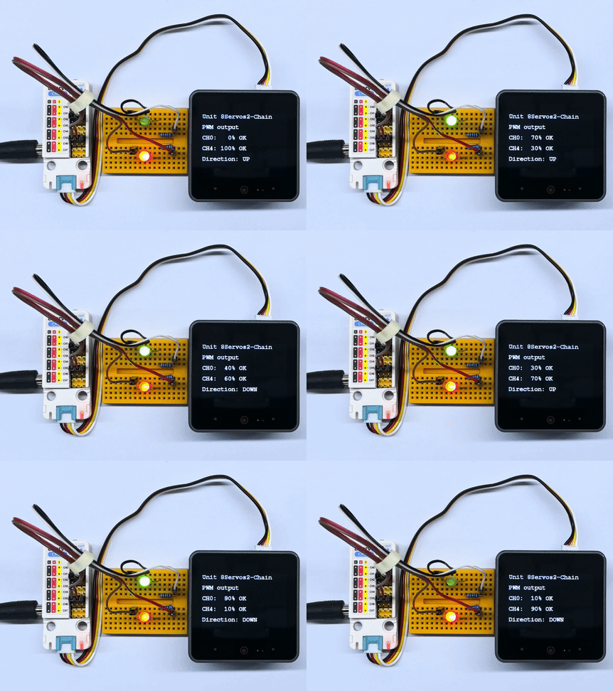
3.5 RGB LED Control
#include <M5Unified.h>
#include "M5Chain.h"

#define TXD_PIN        17
#define RXD_PIN        18
#define GPIO_COUNT     8
#define RGB_CHANNEL    2
#define RGB_LED_COUNT  15
#define RGB_BUFFER_COUNT 16
#define RAINBOW_DURATION_MS 1000
#define RAINBOW_DELAY_MS    20

// Chain state and device list.
Chain M5Chain;
device_list_t *devices_list = nullptr;
uint16_t device_nums = 0;
uint8_t operation_status = 0;
uint8_t unit_id = 0;
bool unit_ready = false;
M5Canvas canvas(&M5.Display);

void showMessage(const char *message)
{
    // Show a status message on the display.
    canvas.clear();
    canvas.setCursor(0, 0);
    canvas.println(message);
    canvas.pushSprite(0, 0);
}

bool updateDeviceList()
{
    // Discover the Unit 8Servos2-Chain device.
    if (!M5Chain.isDeviceConnected()) {
        Serial.println("Chain device not connected");
        return false;
    }

    if (M5Chain.getDeviceNum(&device_nums) != CHAIN_OK || device_nums == 0) {
        Serial.println("Failed to get Chain device count");
        return false;
    }

    devices_list = (device_list_t *)malloc(sizeof(device_list_t));
    if (devices_list == nullptr) {
        Serial.println("Failed to allocate device list");
        return false;
    }

    devices_list->count = device_nums;
    devices_list->devices = (device_info_t *)malloc(sizeof(device_info_t) * device_nums);
    if (devices_list->devices == nullptr || !M5Chain.getDeviceList(devices_list)) {
        free(devices_list->devices);
        free(devices_list);
        devices_list = nullptr;
        Serial.println("Failed to get Chain device list");
        return false;
    }

    for (uint8_t i = 0; i < devices_list->count; i++) {
        if (devices_list->devices[i].device_type == UNIT_8SERVOS2_CHAIN_TYPE_CODE) {
            unit_id = devices_list->devices[i].id;
            break;
        }
    }
    return unit_id != 0;
}

bool configureRgb()
{
    // Configure CH2 as an RGB strip control channel.
    user_gpio_mode_t modes[GPIO_COUNT];
    for (uint8_t i = 0; i < GPIO_COUNT; i++) {
        modes[i] = USER_GPIO_INPUT_MODE;
    }
    modes[RGB_CHANNEL] = USER_GPIO_RGB_MODE;

    chain_status_t status = M5Chain.setServosModeAll(
        unit_id, modes, GPIO_COUNT, &operation_status);
    if (status != CHAIN_OK || operation_status != 1) {
        return false;
    }

    return true;
}

uint32_t wheel(uint8_t position)
{
    // Convert a position on the color wheel to 0xRRGGBB.
    position = 255 - position;
    if (position < 85) {
        return ((uint32_t)(255 - position * 3) << 16) |
               ((uint32_t)(position * 3) << 8);
    }
    if (position < 170) {
        position -= 85;
        return ((uint32_t)(position * 3) << 16) |
               (uint32_t)(255 - position * 3);
    }
    position -= 170;
    return ((uint32_t)(255 - position * 3) << 8) |
           (uint32_t)(position * 3);
}

bool setStripColor(uint32_t color, const char *name)
{
    // Set one color on every LED in the strip.
    // M5Chain requires a 16-entry RGB buffer; the last entry is unused.
    uint32_t colors[RGB_BUFFER_COUNT] = {0};
    for (uint8_t i = 0; i < RGB_LED_COUNT; i++) {
        colors[i] = color;
    }
    bool success = M5Chain.setServosRGBBufferAll(unit_id, colors, RGB_BUFFER_COUNT) == CHAIN_OK;
    uint8_t rgb_config = 0x20 | RGB_LED_COUNT;
    success = M5Chain.setServosRGBConfig(unit_id, RGB_CHANNEL, rgb_config, &operation_status) == CHAIN_OK &&
              operation_status == 1 && success;

    canvas.clear();
    canvas.setCursor(0, 0);
    canvas.println("Unit 8Servos2-Chain");
    canvas.setCursor(0, 40);
    canvas.println("RGB strip");
    canvas.setCursor(0, 80);
    canvas.printf("Color: %s", success ? name : "ERROR");
    canvas.setCursor(0, 120);
    canvas.printf("CH2 LEDs: %u", RGB_LED_COUNT);
    canvas.pushSprite(0, 0);
    Serial.printf("RGB %s: %s\r\n", name, success ? "OK" : "ERROR");
    return success;
}

bool setRainbowStep(uint8_t step)
{
    // Shift the rainbow pattern across the strip.
    // M5Chain requires a 16-entry RGB buffer; the last entry is unused.
    uint32_t colors[RGB_BUFFER_COUNT] = {0};
    for (uint8_t i = 0; i < RGB_LED_COUNT; i++) {
        uint8_t position = (uint8_t)((uint16_t)i * 256 / RGB_LED_COUNT - step * 26);
        colors[i] = wheel(position);
    }
    bool success = M5Chain.setServosRGBBufferAll(unit_id, colors, RGB_BUFFER_COUNT) == CHAIN_OK;
    uint8_t rgb_config = 0x20 | RGB_LED_COUNT;
    success = M5Chain.setServosRGBConfig(unit_id, RGB_CHANNEL, rgb_config, &operation_status) == CHAIN_OK &&
              operation_status == 1 && success;

    canvas.clear();
    canvas.setCursor(0, 0);
    canvas.println("Unit 8Servos2-Chain");
    canvas.setCursor(0, 40);
    canvas.println("RGB strip");
    canvas.setCursor(0, 80);
    canvas.printf("Color: %s", success ? "RAINBOW" : "ERROR");
    canvas.setCursor(0, 120);
    canvas.printf("Step: %u", step);
    canvas.pushSprite(0, 0);
    return success;
}

void setup()
{
    // Disable 5V output on the CoreS3 Grove port.
    auto cfg = M5.config();
    cfg.output_power = false;
    M5.begin(cfg);
    canvas.createSprite(320, 240);
    canvas.setFont(&fonts::FreeMonoBold12pt7b);
    canvas.setTextSize(1);
    Serial.begin(115200);
    Serial.println("Unit 8Servos2-Chain RGB Test");

    // Start Chain UART communication.
    M5Chain.begin(&Serial2, 115200, RXD_PIN, TXD_PIN);
    if (!updateDeviceList() || !configureRgb()) {
        showMessage("RGB setup failed");
        return;
    }
    unit_ready = true;
    showMessage("RGB test ready");
}

void loop()
{
    if (!unit_ready) {
        delay(RAINBOW_DELAY_MS);
        return;
    }

    setStripColor(0xFF0000, "RED");
    delay(500);
    setStripColor(0x00FF00, "GREEN");
    delay(500);
    setStripColor(0x0000FF, "BLUE");
    delay(500);

    // Run a fast rainbow animation continuously for one second.
    uint32_t rainbow_start = millis();
    uint8_t step = 0;
    while (millis() - rainbow_start < RAINBOW_DURATION_MS) {
        setRainbowStep(step++);
        delay(RAINBOW_DELAY_MS);
    }
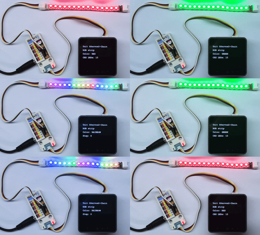
}After startup, the program sets CH2 as the RGB strip control channel and configures 15 RGB LEDs. The strip displays red, green, and blue in sequence, holding each color for 500ms, followed by a fast, continuously scrolling rainbow animation lasting 1 second. The CoreS3 display shows the current color and either the LED count or the rainbow scroll step count. The serial port reports the results of setting the three solid colors, while the rainbow scrolling status is shown on the display.
4. Compile and Upload
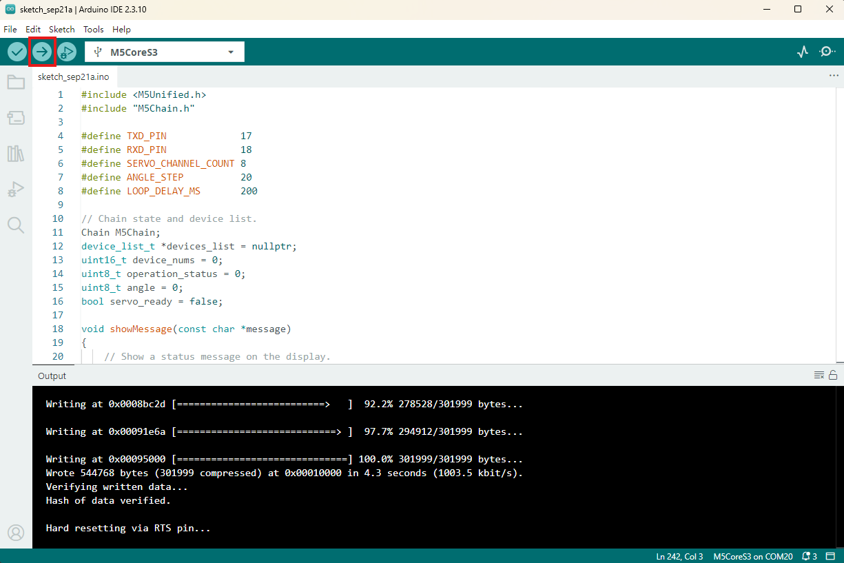
- Copy and paste the example program above into the project code area, select the device port (for details, refer to Program Compilation and Upload), click the Compile and Upload button in the upper-left corner of Arduino IDE, and wait for the program to finish compiling and uploading to the device.