

Arduino Quick Start
2. Devices & Examples
3. M5Unified
4. M5GFX
5. Extensions
Unit
Module
Atomic
Tab5
IoT
Accessories
Stamp LoRa-1262 IF Arduino Tutorial
1. Preparation
Environment setup: Follow the Arduino IDE Getting Started Tutorial to install the IDE, then install the appropriate board package and required driver libraries for your development board.
Required driver library:
Required hardware:
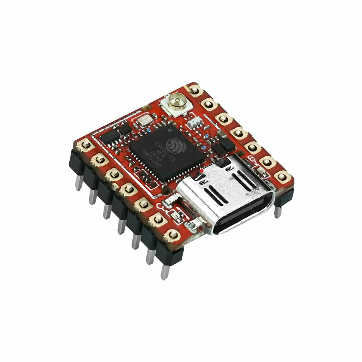

2. Notes
The signal connections between Stamp-C5 DIP and Stamp LoRa-1262 IF are as follows:
| Stamp LoRa-1262 IF Pin | Stamp-C5 GPIO |
|---|---|
| SX_ANT_SW | G23 |
| LORA_IRQ | G0 |
| SX_BUSY | G24 |
| SX_NRST | G25 |
| GND | GND |
| SPI_MISO | G26 |
| SPI_MOSI | G27 |
| SX_NSS | G11 |
| GND | GND |
| SPI_CLK | G12 |

3. Example Programs
This example uses two sets of Stamp-C5 DIP and Stamp LoRa-1262 IF for LoRa point-to-point communication. The transmitter sends strings containing a counter, and the receiver outputs the received data and signal information over the serial port.
The LoRa parameters are as follows:
| Macro | Default | Description |
|---|---|---|
LORA_FREQ | 868.0f | Carrier frequency in MHz |
LORA_BW | 125.0f | Bandwidth in kHz |
LORA_SF | 12 | Spreading factor |
LORA_CR | 5 | Coding rate, corresponding to 4/5 |
LORA_SYNC_WORD | 0x34 | Sync word for identifying matching LoRa packets |
LORA_TX_POWER | 22 | Transmit power in dBm |
LORA_PREAMBLE | 20 | Preamble length in symbols |
The transmitter and receiver should use the same frequency, bandwidth, spreading factor, coding rate, sync word, and preamble length.
3.1 Transmitter
#include <SPI.h>
#include <RadioLib.h>

// Stamp-C5 DIP FPC to Stamp LoRa-1262 IF connections.
#define LORA_MOSI_PIN   GPIO_NUM_27
#define LORA_MISO_PIN   GPIO_NUM_26
#define LORA_SCK_PIN    GPIO_NUM_12
#define LORA_NSS_PIN    GPIO_NUM_11
#define LORA_BUSY_PIN   GPIO_NUM_24
#define LORA_IRQ_PIN    GPIO_NUM_0
#define LORA_RST_PIN    GPIO_NUM_25
#define LORA_ANT_SW_PIN GPIO_NUM_23

// These settings must match on the transmitter and receiver.
#define LORA_FREQ       868.0f
#define LORA_BW         125.0f
#define LORA_SF         12
#define LORA_CR         5
#define LORA_SYNC_WORD  0x34
#define LORA_TX_POWER   22
#define LORA_PREAMBLE   20

SX1262 radio = new Module(LORA_NSS_PIN, LORA_IRQ_PIN, RADIOLIB_NC, LORA_BUSY_PIN);

volatile bool transmittedFlag = false;
int transmissionState = RADIOLIB_ERR_NONE;
uint32_t packetCount = 0;

void IRAM_ATTR setFlag()
{
    transmittedFlag = true;
}

bool initRadio()
{
    // Select the transmit path for the sender.
    // SX_ANT_SW is active high on the S014-IF RF path.
    pinMode(LORA_ANT_SW_PIN, OUTPUT);
    digitalWrite(LORA_ANT_SW_PIN, HIGH);

    // Reset manually because the Module reset pin is RADIOLIB_NC.
    pinMode(LORA_RST_PIN, OUTPUT);
    digitalWrite(LORA_RST_PIN, LOW);
    delay(10);
    digitalWrite(LORA_RST_PIN, HIGH);
    delay(10);

    SPI.begin(LORA_SCK_PIN, LORA_MISO_PIN, LORA_MOSI_PIN, LORA_NSS_PIN);
    const int state = radio.begin(LORA_FREQ, LORA_BW, LORA_SF, LORA_CR,
                                  LORA_SYNC_WORD, LORA_TX_POWER, LORA_PREAMBLE,
                                  3.0f, true);
    if (state != RADIOLIB_ERR_NONE) {
        Serial.printf("[SX1262] init failed, code: %d\n", state);
        return false;
    }
    radio.setPacketSentAction(setFlag);
    return true;
}

void setup()
{
    Serial.begin(115200);
    delay(1000);
    Serial.println(F("Stamp C5-DIP LoRa-1262 IF transmitter"));

    if (!initRadio()) {
        while (true) delay(1000);
    }

    Serial.println(F("[SX1262] init success"));
    transmissionState = radio.startTransmit("Transmitter Ready");
}

void loop()
{
    if (!transmittedFlag) return;
    transmittedFlag = false;

    if (transmissionState == RADIOLIB_ERR_NONE) {
        Serial.println(F("[SX1262] transmission finished"));
    } else {
        Serial.printf("[SX1262] transmit failed, code: %d\n", transmissionState);
    }

    radio.finishTransmit();
    delay(1000);

    String payload = "Stamp C5-DIP LoRa-1262 #" + String(packetCount++);
    Serial.printf("[SX1262] sending: %s\n", payload.c_str());
    transmissionState = radio.startTransmit(payload);
}3.2 Receiver
#include <SPI.h>
#include <RadioLib.h>

// Stamp-C5 DIP FPC to Stamp LoRa-1262 IF connections.
#define LORA_MOSI_PIN   GPIO_NUM_27
#define LORA_MISO_PIN   GPIO_NUM_26
#define LORA_SCK_PIN    GPIO_NUM_12
#define LORA_NSS_PIN    GPIO_NUM_11
#define LORA_BUSY_PIN   GPIO_NUM_24
#define LORA_IRQ_PIN    GPIO_NUM_0
#define LORA_RST_PIN    GPIO_NUM_25
#define LORA_ANT_SW_PIN GPIO_NUM_23

// These settings must match on the transmitter and receiver.
#define LORA_FREQ       868.0f
#define LORA_BW         125.0f
#define LORA_SF         12
#define LORA_CR         5
#define LORA_SYNC_WORD  0x34
#define LORA_TX_POWER   22
#define LORA_PREAMBLE   20

SX1262 radio = new Module(LORA_NSS_PIN, LORA_IRQ_PIN, RADIOLIB_NC, LORA_BUSY_PIN);

volatile bool receivedFlag = false;

void IRAM_ATTR setFlag()
{
    receivedFlag = true;
}

bool initRadio()
{
    pinMode(LORA_ANT_SW_PIN, OUTPUT);
    // Select the receive path for the receiver.
    digitalWrite(LORA_ANT_SW_PIN, LOW);

    // Reset manually because the Module reset pin is RADIOLIB_NC.
    pinMode(LORA_RST_PIN, OUTPUT);
    digitalWrite(LORA_RST_PIN, LOW);
    delay(10);
    digitalWrite(LORA_RST_PIN, HIGH);
    delay(10);

    SPI.begin(LORA_SCK_PIN, LORA_MISO_PIN, LORA_MOSI_PIN, LORA_NSS_PIN);
    const int state = radio.begin(LORA_FREQ, LORA_BW, LORA_SF, LORA_CR,
                                  LORA_SYNC_WORD, LORA_TX_POWER, LORA_PREAMBLE,
                                  3.0f, true);
    if (state != RADIOLIB_ERR_NONE) {
        Serial.printf("[SX1262] init failed, code: %d\n", state);
        return false;
    }
    radio.setPacketReceivedAction(setFlag);
    return true;
}

void setup()
{
    Serial.begin(115200);
    delay(1000);
    Serial.println(F("Stamp C5-DIP LoRa-1262 IF receiver"));

    if (!initRadio()) {
        while (true) delay(1000);
    }

    Serial.println(F("[SX1262] init success"));
    const int state = radio.startReceive();
    if (state != RADIOLIB_ERR_NONE) {
        Serial.printf("[SX1262] receive start failed, code: %d\n", state);
        while (true) delay(1000);
    }
    Serial.println(F("[SX1262] listening"));
}

void loop()
{
    if (!receivedFlag) return;
    receivedFlag = false;

    String payload;
    const int state = radio.readData(payload);
    if (state == RADIOLIB_ERR_NONE) {
        Serial.println(F("[SX1262] packet received"));
        Serial.printf("[SX1262] data: %s\n", payload.c_str());
        Serial.printf("[SX1262] RSSI: %.2f dBm\n", radio.getRSSI());
        Serial.printf("[SX1262] SNR: %.2f dB\n", radio.getSNR());
        Serial.printf("[SX1262] frequency error: %.2f Hz\n", radio.getFrequencyError());
    } else if (state == RADIOLIB_ERR_CRC_MISMATCH) {
        Serial.println(F("[SX1262] CRC error"));
    } else {
        Serial.printf("[SX1262] receive failed, code: %d\n", state);
    }

    radio.finishReceive();
    radio.startReceive();
}4. Compile and Upload
- Select the device port, paste the example program above, and click the Upload button in the upper-left corner of the Arduino IDE. Wait for the program to compile and upload to the device.

5. LoRa Transmission and Reception Test
The transmitter sends a string containing a counter once per second. The receiver prints the received string and displays information such as RSSI.
- Example serial output from the transmitter:
Stamp C5-DIP LoRa-1262 IF transmitter
[SX1262] init success
[SX1262] transmission finished
[SX1262] sending: Stamp C5-DIP LoRa-1262 #0- Example serial output from the receiver:
Stamp C5-DIP LoRa-1262 IF receiver
[SX1262] init success
[SX1262] listening
[SX1262] packet received
[SX1262] data: Stamp C5-DIP LoRa-1262 #0
[SX1262] RSSI: -42.00 dBm
[SX1262] SNR: 9.25 dB