Arduino Quick Start
2. Devices & Examples
3. M5Unified
4. M5GFX
5. Extensions
Unit
Module
Atomic
Tab5
IoT
Accessories
Unit 8Servos2-I2C Arduino Tutorial
1. Preparation
Environment setup: Refer to the Arduino IDE Getting Started Guide to install the IDE, then install the appropriate board package and driver library for your development board.
Libraries used:
Hardware used:

2. Notes
3. Example Programs
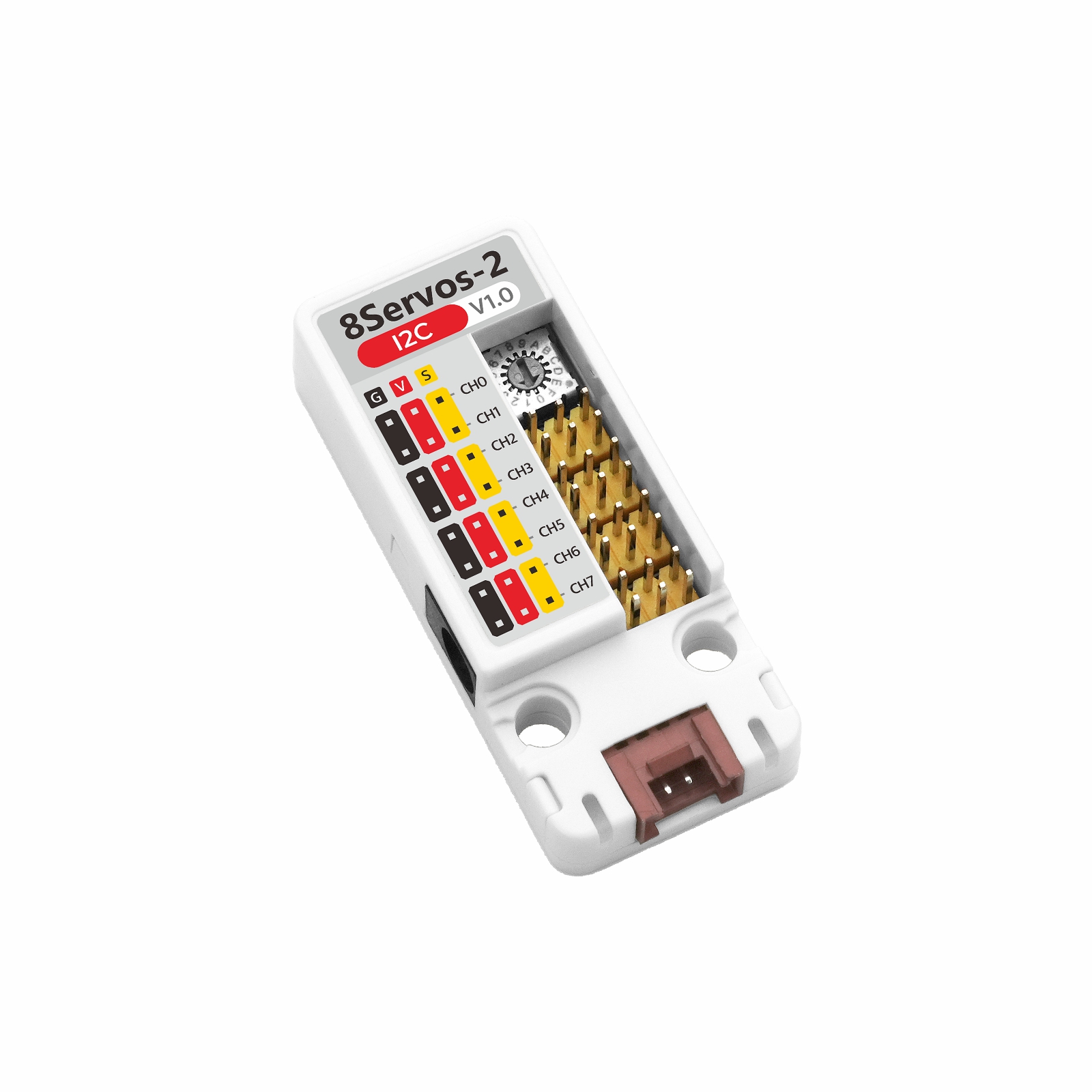
- This tutorial uses a CoreS3 with Unit 8Servos2-I2C to control servos. Unit 8Servos2-I2C communicates over I2C. When connected, the corresponding pins are
G2 (SDA)andG1 (SCL).
0x25, corresponding to address dial position 0 on the Unit;
if the dial is set to another position, change UNIT_I2C_ADDRESS in the program to the corresponding address.cfg.output_power to true in setup().3.1 Servo Control
#include <M5Unified.h>
#include <M5Unit8Servos2.h>

constexpr int I2C_SDA_PIN             = 2;
constexpr int I2C_SCL_PIN             = 1;
constexpr uint8_t UNIT_I2C_ADDRESS    = UNIT_8SERVOS2_DEFAULT_ADDR;
constexpr uint8_t SERVO_CHANNEL_COUNT = 8;
constexpr uint32_t I2C_FREQUENCY      = 400000;
constexpr int16_t STATUS_LINE_HEIGHT  = 40;

// Store the Unit controller and current servo position.
M5Unit8Servos2 servos2;
M5Canvas canvas(&M5.Display);
int16_t angle     = 0;
int8_t angle_step = 20;

// Refresh the display with servo and power data.
void drawStatus(uint16_t dc_voltage, uint16_t grove_voltage, uint16_t current_mA)
{
    canvas.fillScreen(TFT_BLACK);
    canvas.setCursor(0, 0);
    canvas.printf("Unit 8Servos2-I2C\n");
    canvas.setCursor(0, STATUS_LINE_HEIGHT);
    canvas.printf("Angle: %d deg", angle);
    canvas.setCursor(0, STATUS_LINE_HEIGHT * 2);
    canvas.printf("DC: %umV", static_cast<unsigned>(dc_voltage));
    canvas.setCursor(0, STATUS_LINE_HEIGHT * 3);
    canvas.printf("Current: %umA", static_cast<unsigned>(current_mA));
    canvas.setCursor(0, STATUS_LINE_HEIGHT * 4);
    canvas.printf("Grove: %umV", static_cast<unsigned>(grove_voltage));
    canvas.pushSprite(0, 0);
}

void setup()
{
    auto cfg = M5.config();
    cfg.output_power = false;
    M5.begin(cfg);
    canvas.createSprite(M5.Display.width(), M5.Display.height());
    Serial.begin(115200);
    canvas.setFont(&fonts::FreeMonoBold12pt7b);
    canvas.setTextColor(TFT_WHITE, TFT_BLACK);

    Wire.begin(I2C_SDA_PIN, I2C_SCL_PIN, I2C_FREQUENCY);
    while (!servos2.begin(&Wire, UNIT_I2C_ADDRESS, -1, -1, I2C_FREQUENCY)) {
        Serial.println("Unit 8Servos2-I2C not found");
        canvas.fillScreen(TFT_BLACK);
        canvas.setCursor(0, 0);
        canvas.printf("Unit not found");
        canvas.setCursor(0, STATUS_LINE_HEIGHT);
        canvas.printf("Check I2C and address");
        canvas.pushSprite(0, 0);
        delay(1000);
    }

    // Set all channels to servo mode.
    for (uint8_t channel = 0; channel < SERVO_CHANNEL_COUNT; ++channel) {
        servos2.setMode(channel, M5_8SERVOS2_MODE_SERVO);
    }

    // Set both PWM timers to 50 Hz for standard servos.
    servos2.setTimerFrequency(0, 50);
    servos2.setTimerFrequency(1, 50);

    // Read the initial power telemetry.
    const uint16_t dc_voltage    = servos2.getDCVoltage();
    const uint16_t grove_voltage = servos2.getGroveVoltage();
    const uint16_t current_mA    = servos2.getSysCurrent();
    Serial.println("Unit 8Servos2-I2C ready");
    drawStatus(dc_voltage, grove_voltage, current_mA);
}

void loop()
{
    // Apply the current angle to all servo channels.
    for (uint8_t channel = 0; channel < SERVO_CHANNEL_COUNT; ++channel) {
        servos2.setServoAngle(channel, static_cast<uint8_t>(angle));
    }

    // Read and report the latest power telemetry.
    const uint16_t dc_voltage    = servos2.getDCVoltage();
    const uint16_t grove_voltage = servos2.getGroveVoltage();
    const uint16_t current_mA    = servos2.getSysCurrent();
    Serial.printf(
        "Servo angle: %d deg, DC: %u mV, Grove: %u mV, Current: %u mA\n", angle,
        static_cast<unsigned>(dc_voltage), static_cast<unsigned>(grove_voltage),
        static_cast<unsigned>(current_mA));
    drawStatus(dc_voltage, grove_voltage, current_mA);

    // Sweep the servos between 0 and 180 degrees.
    angle += angle_step;
    if (angle >= 180) {
        angle      = 180;
        angle_step = -20;
    } else if (angle <= 0) {
        angle      = 0;
        angle_step = 20;
    }

    delay(200);
}After startup, the program sets all 8 channels to servo mode and controls the servos at 50 Hz. The servos move synchronously between 0° and 180° in 20° steps. The display shows the current angle, DC input voltage, system current, and Grove port voltage, while the serial output reports the same data.
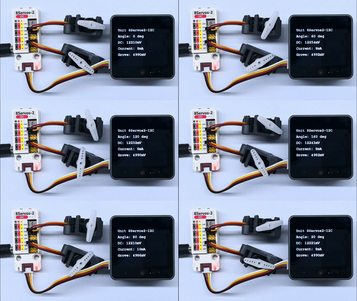
Example serial output:
Unit 8Servos2-I2C ready
Servo angle: 0 deg, DC: 12298 mV, Grove: 5024 mV, Current: 8 mA
Servo angle: 20 deg, DC: 12309 mV, Grove: 5026 mV, Current: 8 mA
Servo angle: 40 deg, DC: 12298 mV, Grove: 5024 mV, Current: 8 mA
Servo angle: 60 deg, DC: 12298 mV, Grove: 5024 mV, Current: 8 mA
Servo angle: 80 deg, DC: 12298 mV, Grove: 5024 mV, Current: 8 mA
Servo angle: 100 deg, DC: 12298 mV, Grove: 5024 mV, Current: 6 mA
Servo angle: 120 deg, DC: 12298 mV, Grove: 5030 mV, Current: 8 mA
Servo angle: 140 deg, DC: 12287 mV, Grove: 5022 mV, Current: 8 mA
Servo angle: 160 deg, DC: 12298 mV, Grove: 5028 mV, Current: 8 mA
Servo angle: 180 deg, DC: 12298 mV, Grove: 5030 mV, Current: 8 mA3.2 Input and Output Control
#include <M5Unified.h>
#include <M5Unit8Servos2.h>

constexpr int I2C_SDA_PIN             = 2;
constexpr int I2C_SCL_PIN             = 1;
constexpr uint8_t UNIT_I2C_ADDRESS    = UNIT_8SERVOS2_DEFAULT_ADDR;
constexpr uint32_t I2C_FREQUENCY      = 400000;
constexpr int16_t STATUS_LINE_HEIGHT  = 40;

M5Unit8Servos2 servos2;
M5Canvas canvas(&M5.Display);
bool output_ch0 = false;
bool output_ch4 = true;

void drawStatus(bool input_ch3, bool input_ch7)
{
    canvas.fillScreen(TFT_BLACK);
    canvas.setCursor(0, 0);
    canvas.printf("Unit 8Servos2-I2C\n");
    canvas.setCursor(0, STATUS_LINE_HEIGHT);
    canvas.printf("CH0 OUT: %s", output_ch0 ? "HIGH" : "LOW");
    canvas.setCursor(0, STATUS_LINE_HEIGHT * 2);
    canvas.printf("CH4 OUT: %s", output_ch4 ? "HIGH" : "LOW");
    canvas.setCursor(0, STATUS_LINE_HEIGHT * 3);
    canvas.printf("CH3 IN:  %s", input_ch3 ? "HIGH" : "LOW");
    canvas.setCursor(0, STATUS_LINE_HEIGHT * 4);
    canvas.printf("CH7 IN:  %s", input_ch7 ? "HIGH" : "LOW");
    canvas.pushSprite(0, 0);
}

void setup()
{
    auto cfg = M5.config();
    cfg.output_power = false;
    M5.begin(cfg);
    canvas.createSprite(M5.Display.width(), M5.Display.height());
    Serial.begin(115200);
    canvas.setFont(&fonts::FreeMonoBold12pt7b);
    canvas.setTextColor(TFT_WHITE, TFT_BLACK);

    Wire.begin(I2C_SDA_PIN, I2C_SCL_PIN, I2C_FREQUENCY);
    while (!servos2.begin(&Wire, UNIT_I2C_ADDRESS, -1, -1, I2C_FREQUENCY)) {
        Serial.println("Unit 8Servos2-I2C not found");
        canvas.fillScreen(TFT_BLACK);
        canvas.setCursor(0, 0);
        canvas.printf("Unit not found");
        canvas.setCursor(0, STATUS_LINE_HEIGHT);
        canvas.printf("Check I2C and address");
        canvas.pushSprite(0, 0);
        delay(1000);
    }

    // Configure output and input channels.
    servos2.setMode(0, M5_8SERVOS2_MODE_OUTPUT);
    servos2.setMode(4, M5_8SERVOS2_MODE_OUTPUT);
    servos2.setMode(3, M5_8SERVOS2_MODE_INPUT);
    servos2.setMode(7, M5_8SERVOS2_MODE_INPUT);
    servos2.setInputPull(3, M5_8SERVOS2_PULL_UP);
    servos2.setInputPull(7, M5_8SERVOS2_PULL_UP);
}

void loop()
{
    // Set opposite output levels and read the input levels.
    servos2.setDigitalOutput(0, output_ch0);
    servos2.setDigitalOutput(4, output_ch4);
    const bool input_ch3 = servos2.getDigitalInput(3);
    const bool input_ch7 = servos2.getDigitalInput(7);

    Serial.printf("CH0: %s, CH4: %s, CH3: %s, CH7: %s\n",
                  output_ch0 ? "HIGH" : "LOW", output_ch4 ? "HIGH" : "LOW",
                  input_ch3 ? "HIGH" : "LOW", input_ch7 ? "HIGH" : "LOW");
    drawStatus(input_ch3, input_ch7);

    output_ch0 = !output_ch0;
    output_ch4 = !output_ch0;
    delay(500);
}The external LEDs connected to CH0 and CH4 alternate between on and off, with opposite states on the two channels, switching approximately every 500ms. For the demonstration, externally connect CH3 to CH0 and CH7 to CH4 to read the corresponding HIGH and LOW levels. The display and serial output both show the two output states and the two input levels.
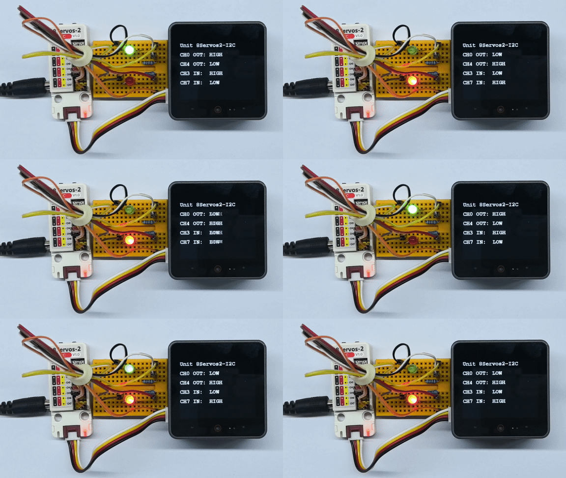
3.3 ADC Acquisition
#include <M5Unified.h>
#include <M5Unit8Servos2.h>

constexpr int I2C_SDA_PIN             = 2;
constexpr int I2C_SCL_PIN             = 1;
constexpr uint8_t UNIT_I2C_ADDRESS    = UNIT_8SERVOS2_DEFAULT_ADDR;
constexpr uint32_t I2C_FREQUENCY      = 400000;
constexpr int16_t STATUS_LINE_HEIGHT  = 40;

M5Unit8Servos2 servos2;
M5Canvas canvas(&M5.Display);

void drawStatus(uint16_t adc_raw, uint16_t voltage_mV)
{
    canvas.fillScreen(TFT_BLACK);
    canvas.setCursor(0, 0);
    canvas.printf("Unit 8Servos2-I2C\n");
    canvas.setCursor(0, STATUS_LINE_HEIGHT);
    canvas.printf("Channel: CH4");
    canvas.setCursor(0, STATUS_LINE_HEIGHT * 2);
    canvas.printf("ADC Raw: %u", static_cast<unsigned>(adc_raw));
    canvas.setCursor(0, STATUS_LINE_HEIGHT * 3);
    canvas.printf("Voltage: %umV", static_cast<unsigned>(voltage_mV));
    canvas.pushSprite(0, 0);
}

void setup()
{
    auto cfg = M5.config();
    cfg.output_power = false;
    M5.begin(cfg);
    canvas.createSprite(M5.Display.width(), M5.Display.height());
    Serial.begin(115200);
    canvas.setFont(&fonts::FreeMonoBold12pt7b);
    canvas.setTextColor(TFT_WHITE, TFT_BLACK);

    Wire.begin(I2C_SDA_PIN, I2C_SCL_PIN, I2C_FREQUENCY);
    while (!servos2.begin(&Wire, UNIT_I2C_ADDRESS, -1, -1, I2C_FREQUENCY)) {
        Serial.println("Unit 8Servos2-I2C not found");
        canvas.fillScreen(TFT_BLACK);
        canvas.setCursor(0, 0);
        canvas.printf("Unit not found");
        canvas.setCursor(0, STATUS_LINE_HEIGHT);
        canvas.printf("Check I2C and address");
        canvas.pushSprite(0, 0);
        delay(1000);
    }

    // Configure CH4 for ADC input.
    servos2.setMode(4, M5_8SERVOS2_MODE_ADC);
}

void loop()
{
    // Read the latest raw ADC value and voltage.
    const uint16_t adc_raw    = servos2.getADCRaw(4);
    const uint16_t voltage_mV = servos2.getVoltageMV(4);
    Serial.printf("CH4 ADC: %u, Voltage: %umV\n", static_cast<unsigned>(adc_raw),
                  static_cast<unsigned>(voltage_mV));
    drawStatus(adc_raw, voltage_mV);
    delay(200);
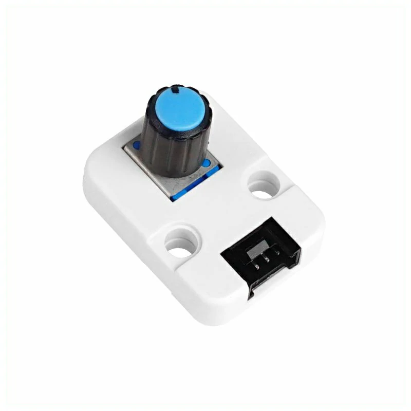
}After startup, the program sets CH4 to ADC mode and continuously reads the raw ADC value and the converted voltage. The CoreS3 display shows the ADC value and voltage for CH4, while the serial port outputs the acquisition results.
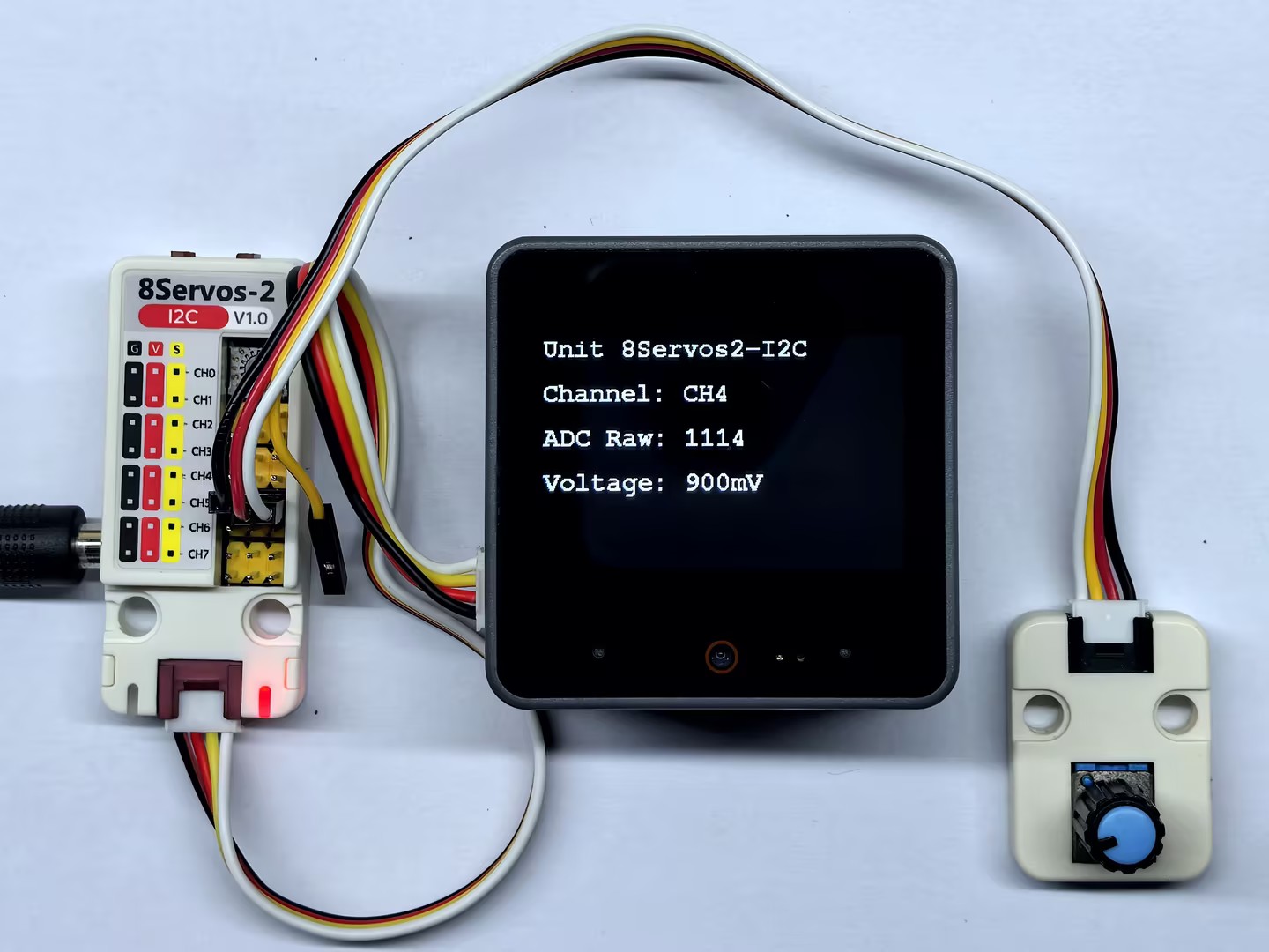
3.4 PWM Output
#include <M5Unified.h>
#include <M5Unit8Servos2.h>

constexpr int I2C_SDA_PIN             = 2;
constexpr int I2C_SCL_PIN             = 1;
constexpr uint8_t UNIT_I2C_ADDRESS    = UNIT_8SERVOS2_DEFAULT_ADDR;
constexpr uint32_t I2C_FREQUENCY      = 400000;
constexpr uint16_t PWM_FREQUENCY      = 1000;
constexpr int16_t STATUS_LINE_HEIGHT  = 40;

M5Unit8Servos2 servos2;
M5Canvas canvas(&M5.Display);
uint8_t duty_ch0 = 0;
uint8_t duty_ch4 = 100;
int8_t duty_step = 10;

void drawStatus()
{
    canvas.fillScreen(TFT_BLACK);
    canvas.setCursor(0, 0);
    canvas.printf("Unit 8Servos2-I2C\n");
    canvas.setCursor(0, STATUS_LINE_HEIGHT);
    canvas.printf("CH0: %u%%", static_cast<unsigned>(duty_ch0));
    canvas.setCursor(0, STATUS_LINE_HEIGHT * 2);
    canvas.printf("CH4: %u%%", static_cast<unsigned>(duty_ch4));
    canvas.setCursor(0, STATUS_LINE_HEIGHT * 3);
    canvas.printf("Frequency: %uHz", static_cast<unsigned>(PWM_FREQUENCY));
    canvas.pushSprite(0, 0);
}

void setup()
{
    auto cfg = M5.config();
    cfg.output_power = false;
    M5.begin(cfg);
    canvas.createSprite(M5.Display.width(), M5.Display.height());
    Serial.begin(115200);
    canvas.setFont(&fonts::FreeMonoBold12pt7b);
    canvas.setTextColor(TFT_WHITE, TFT_BLACK);

    Wire.begin(I2C_SDA_PIN, I2C_SCL_PIN, I2C_FREQUENCY);
    while (!servos2.begin(&Wire, UNIT_I2C_ADDRESS, -1, -1, I2C_FREQUENCY)) {
        Serial.println("Unit 8Servos2-I2C not found");
        canvas.fillScreen(TFT_BLACK);
        canvas.setCursor(0, 0);
        canvas.printf("Unit not found");
        canvas.setCursor(0, STATUS_LINE_HEIGHT);
        canvas.printf("Check I2C and address");
        canvas.pushSprite(0, 0);
        delay(1000);
    }

    // Configure CH0 and CH4 for PWM output.
    servos2.setMode(0, M5_8SERVOS2_MODE_PWM);
    servos2.setMode(4, M5_8SERVOS2_MODE_PWM);
    servos2.setTimerFrequency(0, PWM_FREQUENCY);
    servos2.setTimerFrequency(1, PWM_FREQUENCY);
}

void loop()
{
    // Apply opposite duty cycles to CH0 and CH4.
    servos2.setPWMDuty(0, duty_ch0);
    servos2.setPWMDuty(4, duty_ch4);
    Serial.printf("CH0: %u%%, CH4: %u%%\n", static_cast<unsigned>(duty_ch0),
                  static_cast<unsigned>(duty_ch4));
    drawStatus();

    if (duty_ch0 >= 100) {
        duty_step = -10;
    } else if (duty_ch0 == 0) {
        duty_step = 10;
    }
    duty_ch0 = static_cast<uint8_t>(duty_ch0 + duty_step);
    duty_ch4 = 100 - duty_ch0;
    delay(50);
}The external LEDs connected to CH0 and CH4 fade in opposite directions: as one gradually brightens, the other dims. The direction reverses when an LED reaches maximum brightness or turns off. The brightness updates approximately every 50ms. The display shows both duty cycles and the 1000Hz output frequency, while the serial port outputs both duty cycles.
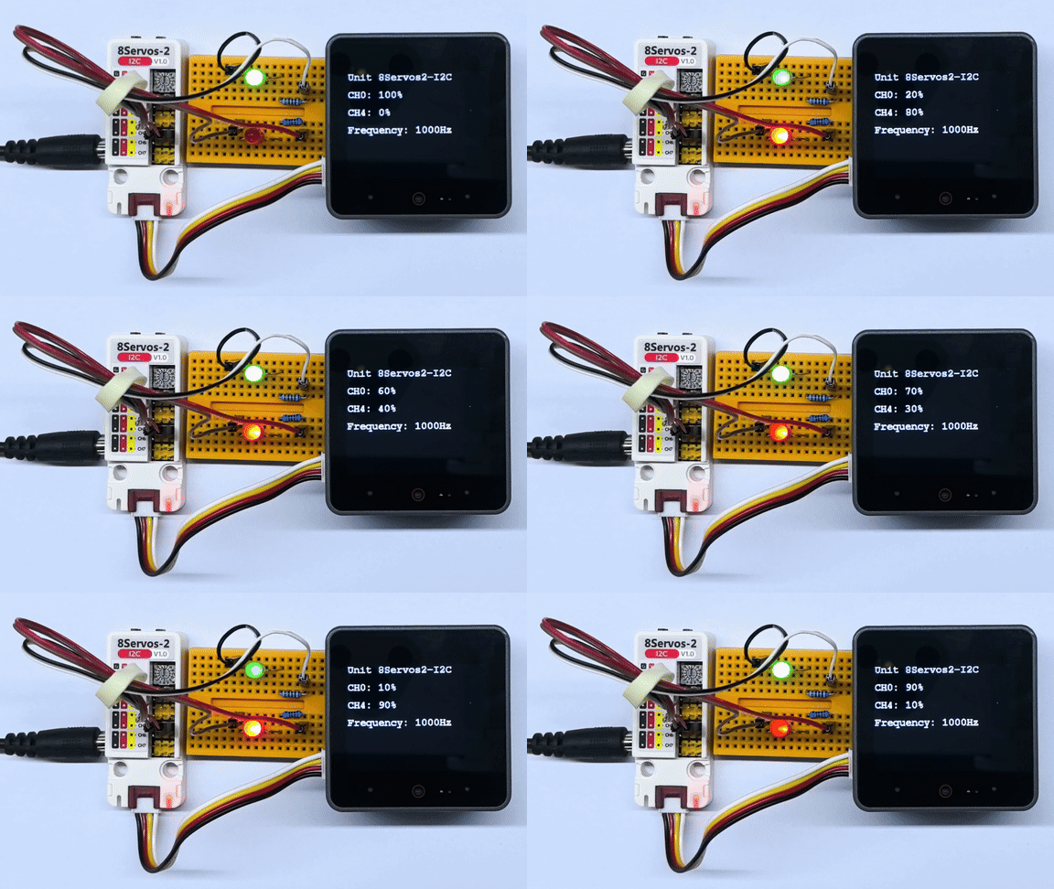
3.5 RGB LED Control
#include <M5Unified.h>
#include <M5Unit8Servos2.h>

constexpr int I2C_SDA_PIN             = 2;
constexpr int I2C_SCL_PIN             = 1;
constexpr uint8_t UNIT_I2C_ADDRESS    = UNIT_8SERVOS2_DEFAULT_ADDR;
constexpr uint8_t RGB_CHANNEL         = 2;
constexpr uint8_t RGB_LED_COUNT       = 15;
constexpr uint8_t RGB_BRIGHTNESS_PERCENT = 5;
constexpr uint32_t I2C_FREQUENCY      = 400000;
constexpr int16_t STATUS_LINE_HEIGHT  = 40;

M5Unit8Servos2 servos2;
M5Canvas canvas(&M5.Display);

uint32_t colorWheel(uint8_t position)
{
    position = 255 - position;
    if (position < 85) {
        return ((255 - position * 3) << 16) | (position * 3);
    }
    if (position < 170) {
        position -= 85;
        return (position * 3 << 8) | (255 - position * 3);
    }
    position -= 170;
    return (position * 3 << 16) | (255 - position * 3 << 8);
}

void showStatus(const char *mode)
{
    canvas.fillScreen(TFT_BLACK);
    canvas.setCursor(0, 0);
    canvas.printf("Unit 8Servos2-I2C\n");
    canvas.setCursor(0, STATUS_LINE_HEIGHT);
    canvas.printf("Channel: CH2");
    canvas.setCursor(0, STATUS_LINE_HEIGHT * 2);
    canvas.printf("Mode: %s", mode);
    canvas.setCursor(0, STATUS_LINE_HEIGHT * 3);
    canvas.printf("LEDs: %u", static_cast<unsigned>(RGB_LED_COUNT));
    canvas.setCursor(0, STATUS_LINE_HEIGHT * 4);
    canvas.printf("Brightness: %u%%", static_cast<unsigned>(RGB_BRIGHTNESS_PERCENT));
    canvas.pushSprite(0, 0);
}

// Scale each RGB component before writing the buffer.
uint32_t applyBrightness(uint32_t color)
{
    const uint8_t red   = (color >> 16) & 0xFF;
    const uint8_t green = (color >> 8) & 0xFF;
    const uint8_t blue  = color & 0xFF;
    return ((red * RGB_BRIGHTNESS_PERCENT / 100) << 16) |
           ((green * RGB_BRIGHTNESS_PERCENT / 100) << 8) |
           (blue * RGB_BRIGHTNESS_PERCENT / 100);
}

void setSolidColor(uint32_t color)
{
    uint32_t colors[RGB_LED_COUNT] = {0};
    for (uint8_t i = 0; i < RGB_LED_COUNT; ++i) {
        colors[i] = applyBrightness(color);
    }
    servos2.setRGBBuffer(colors, RGB_LED_COUNT);
    servos2.setRGBConfig(RGB_CHANNEL, RGB_LED_COUNT, true);
}

void setRainbow(uint8_t offset)
{
    uint32_t colors[RGB_LED_COUNT] = {0};
    for (uint8_t i = 0; i < RGB_LED_COUNT; ++i) {
        const uint8_t position = static_cast<uint8_t>(
            (static_cast<uint16_t>(i) * 256 / RGB_LED_COUNT + 256 - offset) & 0xFF);
        colors[i] = applyBrightness(colorWheel(position));
    }
    servos2.setRGBBuffer(colors, RGB_LED_COUNT);
    servos2.setRGBConfig(RGB_CHANNEL, RGB_LED_COUNT, true);
}

void setup()
{
    auto cfg = M5.config();
    M5.begin(cfg);
    canvas.createSprite(M5.Display.width(), M5.Display.height());
    Serial.begin(115200);
    canvas.setFont(&fonts::FreeMonoBold12pt7b);
    canvas.setTextColor(TFT_WHITE, TFT_BLACK);

    Wire.begin(I2C_SDA_PIN, I2C_SCL_PIN, I2C_FREQUENCY);
    while (!servos2.begin(&Wire, UNIT_I2C_ADDRESS, -1, -1, I2C_FREQUENCY)) {
        Serial.println("Unit 8Servos2-I2C not found");
        canvas.fillScreen(TFT_BLACK);
        canvas.setCursor(0, 0);
        canvas.printf("Unit not found");
        canvas.setCursor(0, STATUS_LINE_HEIGHT);
        canvas.printf("Check I2C and address");
        canvas.pushSprite(0, 0);
        delay(1000);
    }

    // Configure CH2 for RGB strip control.
    servos2.setMode(RGB_CHANNEL, M5_8SERVOS2_MODE_RGB);
}

void loop()
{
    const uint32_t solid_colors[] = {0xFF0000, 0x00FF00, 0x0000FF};
    const char *solid_names[]     = {"Red", "Green", "Blue"};

    // Show red, green, and blue for 200 ms each.
    for (uint8_t i = 0; i < 3; ++i) {
        setSolidColor(solid_colors[i]);
        showStatus(solid_names[i]);
        Serial.printf("CH2 RGB: %s, Brightness: %u%%\n", solid_names[i],
                      static_cast<unsigned>(RGB_BRIGHTNESS_PERCENT));
        delay(200);
    }

    // Scroll a rainbow pattern continuously for 1 second.
    const uint32_t rainbow_start = millis();
    uint8_t rainbow_offset        = 0;
    while (millis() - rainbow_start < 1000) {
        setRainbow(rainbow_offset);
        showStatus("Rainbow");
        rainbow_offset += 16;
        delay(20);
    }
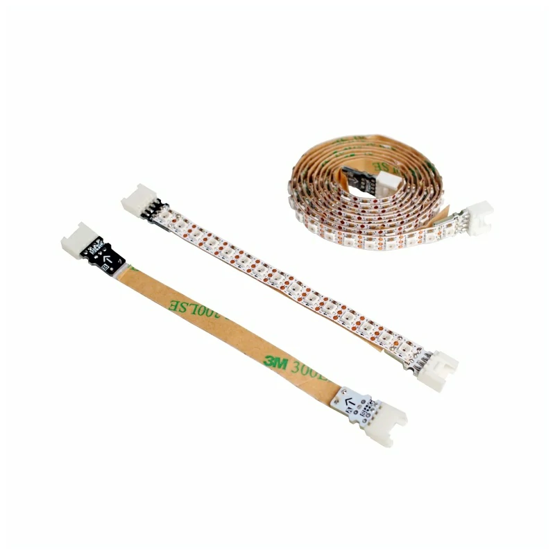
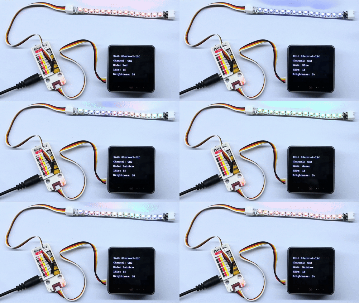
}The 15 RGB LEDs on CH2 display red, green, and blue in sequence, holding each color for approximately 200ms. A rainbow pattern then scrolls from the 1st LED toward the 15th, updating approximately every 20ms for about 1 second before the sequence repeats. The RGB components of all colors are scaled to 5%. The CoreS3 display shows the channel, mode, LED count, and brightness setting. The serial port outputs the color name and brightness setting only during the red, green, and blue phases.
4. Compile and Upload
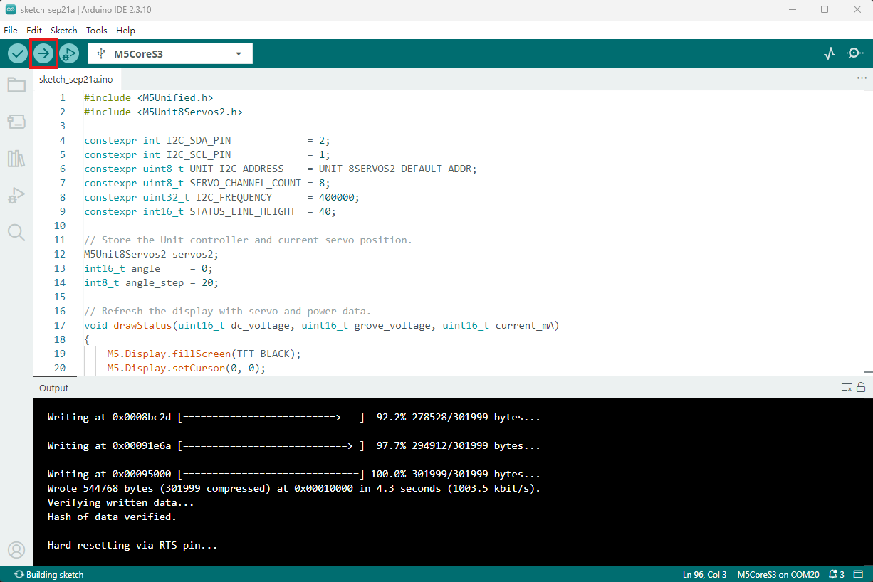
- Copy the example program above into the project code area, select the device port (see Program Compilation and Upload for details), then click the compile and upload button in the upper-left corner of Arduino IDE. Wait for the program to finish compiling and uploading to the device.